Disclaimer
The information contained in this document is believed to be accurate in all respects but is not warranted by Algo. The information is subject to change without notice and should not be construed in any way as a commitment by Algo or any of its affiliates or subsidiaries. Algo and its affiliates and subsidiaries assume no responsibility for any errors or omissions in this document. Revisions of this document or new editions of it may be issued to incorporate such changes. Algo assumes no liability for damages or claims resulting from any use of this manual or such products, software, firmware, and/or hardware.
No part of this document can be reproduced or transmitted in any form or by any means – electronic or mechanical – for any purpose without written permission from Algo.
For additional information or technical assistance in North America, please contact Algo’s support team:
1-604-454-3792
support@algosolutions.com
About
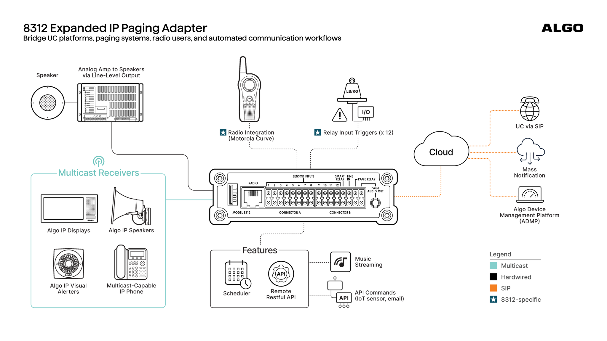
The 8312 Expanded IP Paging Adapter builds on the SIP paging capabilities of the 8301 IP Paging Adapter & Scheduler, combining UC-based voice paging, scheduling, legacy amplifier integration, handheld radio integration, and relay-triggered workflows in a single network-connected device. Distribute audio from UC platforms to overhead paging systems, compatible radio users, or both simultaneously.
By bridging UC communications, PA infrastructure, and handheld radio systems, the 8312 extends critical messages across a wider range of physical environments and operational teams. Optimized to integrate base station-free handheld radio systems, the 8312 is compatible with Motorola Curve radios. For radio systems that use a base station, the Algo 8301 may also be used. Contact Algo to discuss compatibility with other handheld radio systems.
Example 8312 Deployment with Paging, Base Station-Free Handheld Radio, and Sensor-Triggered Workflows
What’s Included | Purchased Separately (Optional) |
|---|---|
| Radio Connector Cable – Motorola Curve (79-00062) |
Hardware Overview
The 8312 provides interfaces for SIP paging, analog audio, radio integration, relay-controlled automation, and sensor-triggered workflows. This section describes the physical interfaces and LED indicators on the device.
Device Interfaces
This section identifies the physical interfaces on the 8312 and describes their function.
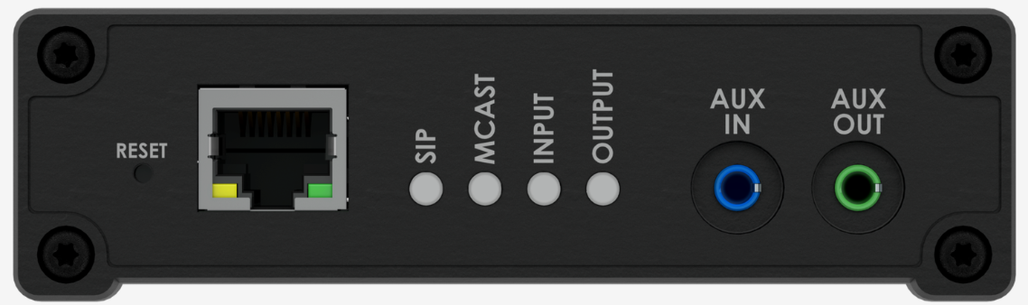
8312 Front View
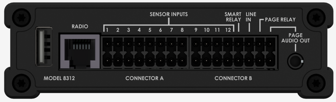
8312 Back View
Interface | Description |
|---|---|
RESET | A recessed RESET (RST) button to reset the 8312 during power-up. |
RJ45 Ethernet Jack | The 8312 provides an RJ45 jack for network connection. A cable run from the switch can be terminated to a modular jack with connection by patch cord or terminated with an RJ45 plug. PoE (Power over Ethernet) must be 48 V 350 mA IEEE 802.3af compliant whether provided by the network switch or injector. There are two lights on the Ethernet jack:
Under normal conditions, the Amber light will turn on immediately after the Ethernet cable is first connected. This indicates that PoE power has been successfully applied. Once the device connects to the network, it will switch to the Green light, which will typically flicker indicating traffic on the network. |
AUX IN 3.5 mm Jack (Front) | Analog line level input from a smartphone or similar device for music input. Non-isolated. |
AUX OUT 3.5 mm Jack (Front) | Analog line level output for compatible PC speakers or headsets. Non-isolated. |
PAGE AUDIO OUT | Line-level audio output with adjustable output levels. Two options:
|
PAGE RELAY | Relay output. Max 30 V 50 mA (normally open). |
LINE IN | Terminal block to external audio source. Balanced and isolated wire pair input. Polarity independent.
|
SMART RELAY | Dry-contact input that supports fault detection. It can be connected to compatible supervised external devices, including Algo accessories and third-party devices that use normally open or normally closed dry contacts with end-of-line (EOL) supervision, such as the 1202 Call Button, 1203 Call Switch, 1204 Volume Control, 1205 Audio Interface, 1211 Single Button, 1212 Dual Button, and 2507 Ring Detector. |
12 SENSOR INPUTS | Dry-contact inputs that support normally open or normally closed external devices but do not provide fault detection or supervision. |
RADIO | RJ12 port for Motorola Curve radio input/output (via a customized Radio Connector Cable). The RADIO input is connected in parallel with LINE IN. |
USB | USB-A connector (Reserved for future use). |
LED Indicators
All four blue lights will be on during power up and boot process.
LED Indicator | Description |
|---|---|
SIP | A steady light will appear when a SIP extension is registered. The light will blink when the device is engaged in a SIP call. |
MCAST | A steady light will appear when the 8312 receives multicast messages as a Receiver. The light will blink when the 8312 sends output to Receivers as a Transmitter. |
INPUT | The INPUT LED turns on when the configured analog input is actively in use. It does not indicate whether a cable is physically connected. |
OUTPUT | The output light will be on when analog output is enabled. |
Getting Started
This section describes how to install the 8312, access its web interface, and perform the initial SIP configuration.
Installing the Device
The 8312 is wall-mountable in a horizontal orientation using the supplied bracket. Example installation on ½” drywall:
Use appropriate drywall anchors for #8 screws, and predrill per the anchor manufacturer’s instructions. Insert 4 anchors into the wall, and then attach the bracket to the wall anchors using #8 screws.
Snap the 8312 into the bracket.
Connect the 8312 to a PoE network switch.
(Optional) Connect the PAGE AUDIO OUT (terminal block or 3.5 mm jack) to an amplifier. The 8312 provides an isolated (dry) audio output and dry contact closure.
Obtaining the Device IP Address
You will need the device IP address to access its web interface. You can find the device IP address using one of the following methods:
Use the RESET button to let the device announce its IP address.
Use other network discovery methods.
To obtain the device IP address using the device RESET button:
Connect the device to a PoE network switch.
Connect a headset to the AUX OUT port.
Caution
The 'Page Audio' Output Level is set to the highest level (+4dBU 10k), by default. This setting may be too loud for headset output. Before putting on the headset, adjust the volume under Basic Settings → Features → Audio → 'Page Audio' Output Level and select a lower value.
The blue SIP LED will turn on until boot-up is completed (about 1 minute).
After the SIP LED turns off, locate the sunken RESET button on the front panel. Press the RESET button using a straightened safety pin. Once pressed, you will hear the IP address over the headset.
After you have noted down the IP address, press the RESET button again to stop the repetitive announcement.
Alternative Methods to Obtain Device IP
Alternative Methods to Obtain Device IP
Alternatively, use one of the following methods to find devices on your local network and identify their IP and MAC addresses. All Algo devices have a MAC address starting with 00:22:ee. Use this prefix to quickly identify your Algo devices.
Log in to your router or DHCP server and check the DHCP client list.
Use a network scanning tool.
Use a network management software to view DHCP-assigned IPs.
Open a terminal or command prompt and check your ARP table:
Windows:
arp -aLinux/macOS:
arp -aorip neigh
Accessing the Web Interface
You can configure the device through its web interface. The web interface does not require an additional purchase. All settings, integrations, and file uploads can be accessed via the web interface.
To access the device web interface:
Enter the device IP address into your web browser.
Log in using the default password: algo.
Note
This password can be changed in Advanced Settings → Admin tab after you log in for the first time. It is highly recommended to change the default password if the device is directly connected to a public network.
Logging out of the Device
Use the Logout tab to securely end your current web interface session. Logging out helps prevent unauthorized access to the device, especially when using a shared or public computer.

To log out from the device web interface:
Select the Logout tab.
Changing the Login Password
You can change the login password in Advanced Settings → Admin tab. It is highly recommended to change the default password if the device is directly connected to a public network.
To change the login password:
Go to Advanced Settings → Admin → Management.
Enter the Old Password.
Enter your new Password.
Repeat the new password in Confirmation.
Select Save.
The device reboots to apply the new setting.
Login Password Requirements
The login password requirements depend on the Force Strong Password setting.
Force Strong Password Enabled | Force Strong Password Disabled |
|---|---|
|
|
To enable strong password:
Go to Advanced Settings → Admin → Management.
Set Force Strong Password to Enabled.
Select Save.
Before you can save the changes, your login password must meet the strong password requirements listed above. If it does not, change your login password first.
Making Your First SIP Call
This procedure demonstrates the minimum configuration required to place a SIP paging call.
To make your first SIP call:
Go to Basic Settings → SIP.
Enter the SIP server IP address or domain name into SIP Domain.
Enter the following. This information will be available from your IT Administrator.
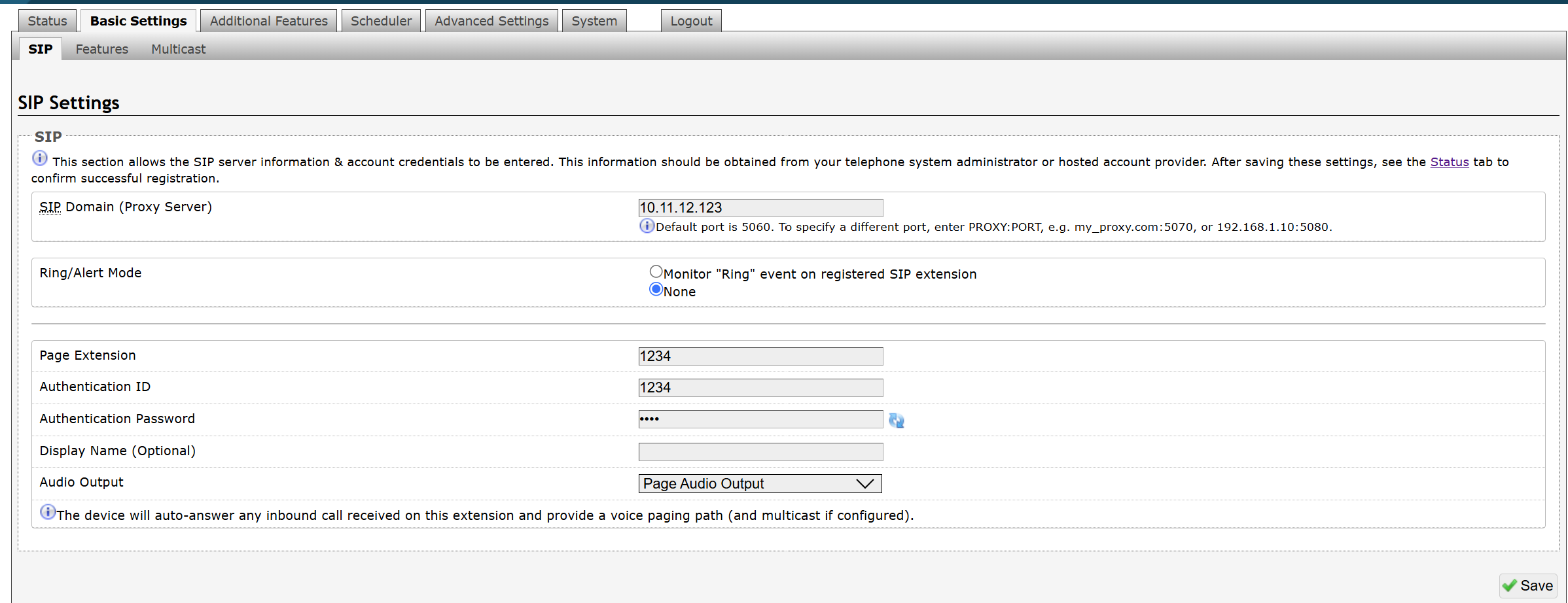
Page Extension
Authentication ID
Authentication Password
Make a call to the 8312 by dialing the SIP extension of the 8312 from a telephone, IP phone, or SIP application.
After completing the initial SIP configuration, you can configure additional features such as ring extensions, multicast paging, emergency alerts, relay-triggered actions, background music streaming, and scheduled announcements.
Viewing Device Status
The web interface has a Status page which, by default, is available both before and after login.
.png)
Depending on your device configuration and firmware version, the Status page may display the following information:
|
|
Restricting the Status Page to Logged-In Users
The Status page can be restricted to logged-in users.
To restrict the Status page to logged-in users:
Go to Advanced Settings → Admin → General.
Set Show Status Section on Status Page when Logged Out to Off.
Select Save.
Customizing Your Status Page
You can customize the content of the Status page.
To customize your status page:
Go to Advanced Settings → Admin.
Configure the General section:
Introduction Section on Status Page: Select whether to show the introduction text on the login screen.
Display Switch Port ID on Status Page: Select whether to display the switch port ID on Status page.
Select Save.
Register Your Product
Register your product to receive the latest firmware and product updates, important service notifications, and a 3-year extended warranty for IP products.
To register your product:
Do one of the following:
Scan this QR code:

Security
Algo devices use TLS for provisioning and SIP signaling to help protect against cyberattacks that attempt to intercept, replicate, or alter Algo products. Algo devices also come pre-loaded with certificates from a list of trusted certificate authorities (CA) to ensure secure communication with reputable sources. Pre-installed trusted certificates are not visible to users and are separate from those in the ‘certs’ folder.
For further details, see Securing Algo Endpoints: TLS and Mutual Authentication.
Wiring Connections
This section describes how to connect the 8312 to external devices. It includes wiring examples for connecting the 8312 to a paging amplifier, as well as instructions for connecting relay and sensor input devices to the SMART RELAY and SENSOR INPUTS for event-triggered automation.
Wiring an Amplifier
The wiring diagram below illustrates one of the most common use cases, where the PAGE AUDIO OUT of the 8312 is connected directly to the dry audio input on an amplifier with an input impedance between 600 Ohm and 10k Ohm.
The optional dry contact closure can be used to activate the amplifier(if required).
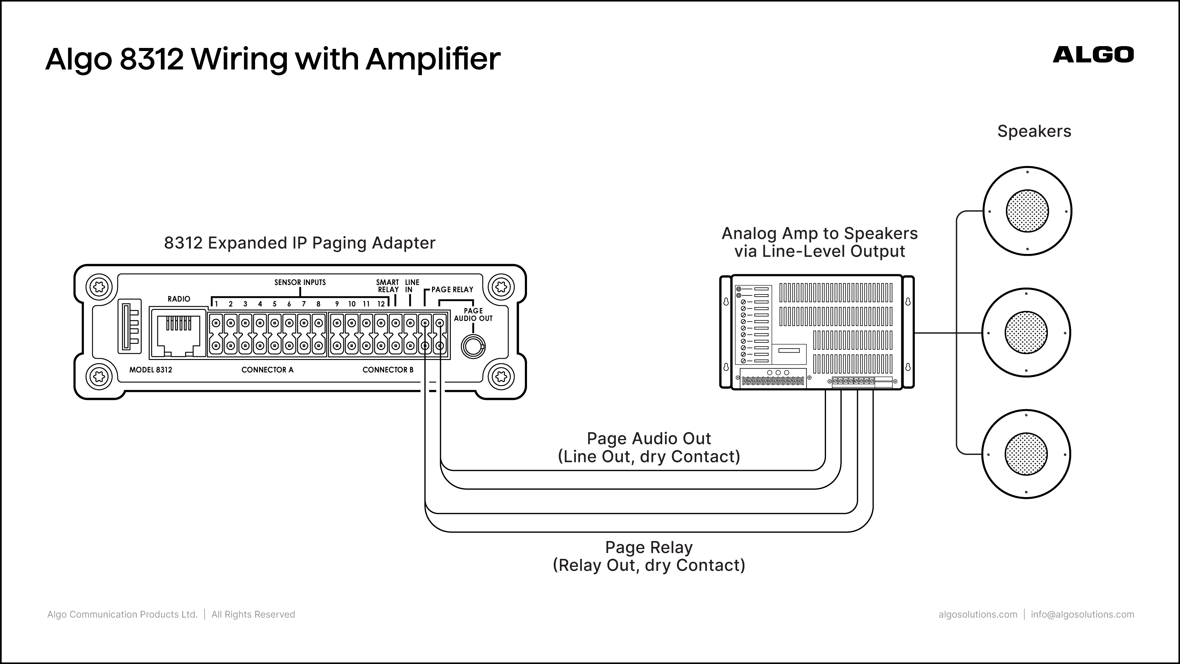
The output level of the 8312 can be adjusted to match the amplifier’s input specification.
To adjust the audio output level of the 8312:
Go to Basic Settings → Features → Audio.
Select a 'Page Audio' Output Level.
Wiring an Input Device to the SMART RELAY or SENSOR INPUTS
Note
The 8312 does not support the direct connection of dynamic microphones. Direct connection of a dynamic microphone to the 8312 may result in no audio or improper operation.
To connect a dynamic microphone (e.g., Sennheiser E835), which does not require phantom power, an Algo 1205 Audio Interface is required. The 1205 provides the necessary preamplification, impedance matching, and interface to ensure proper audio input.
You can connect compatible Algo accessories or third-party dry-contact devices to the SMART RELAY or SENSOR INPUTS of the 8312.
You will need the following:
Pluggable terminal blocks (included in the 8312 package)
A single twisted-pair (24 AWG)
To wire a relay input device or sensor input device to the 8312:
Connect the two pluggable terminal blocks to the CONNECTOR A and CONNECTOR B sections of your 8312 respectively.
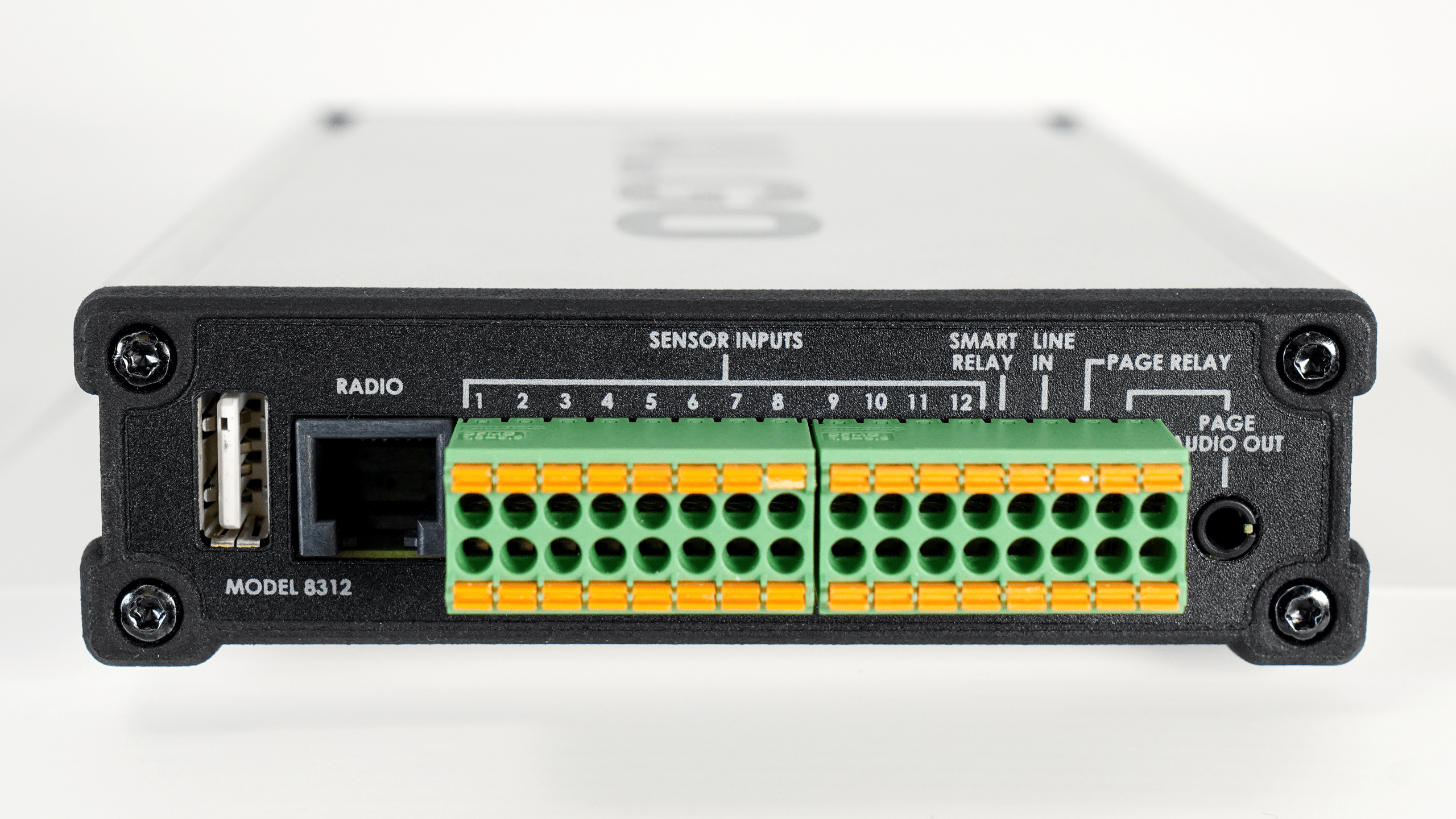
Connect one end of a single twisted-pair (24 AWG) to your input device.
Strip approximately 6–8 mm (1/4–5/16 in.) of insulation from the other end of the single twisted-pair.
Do one of the following:
To connect a sensor input device, choose terminals from SENSOR INPUTS 1 - 12.
To connect a relay input device, select the SMART RELAY terminals.
Use your finger or a small flat-head screwdriver to press down the corresponding orange release button next to the terminal. Keep the button pressed while inserting one conductor of the wire into the round opening below the button.
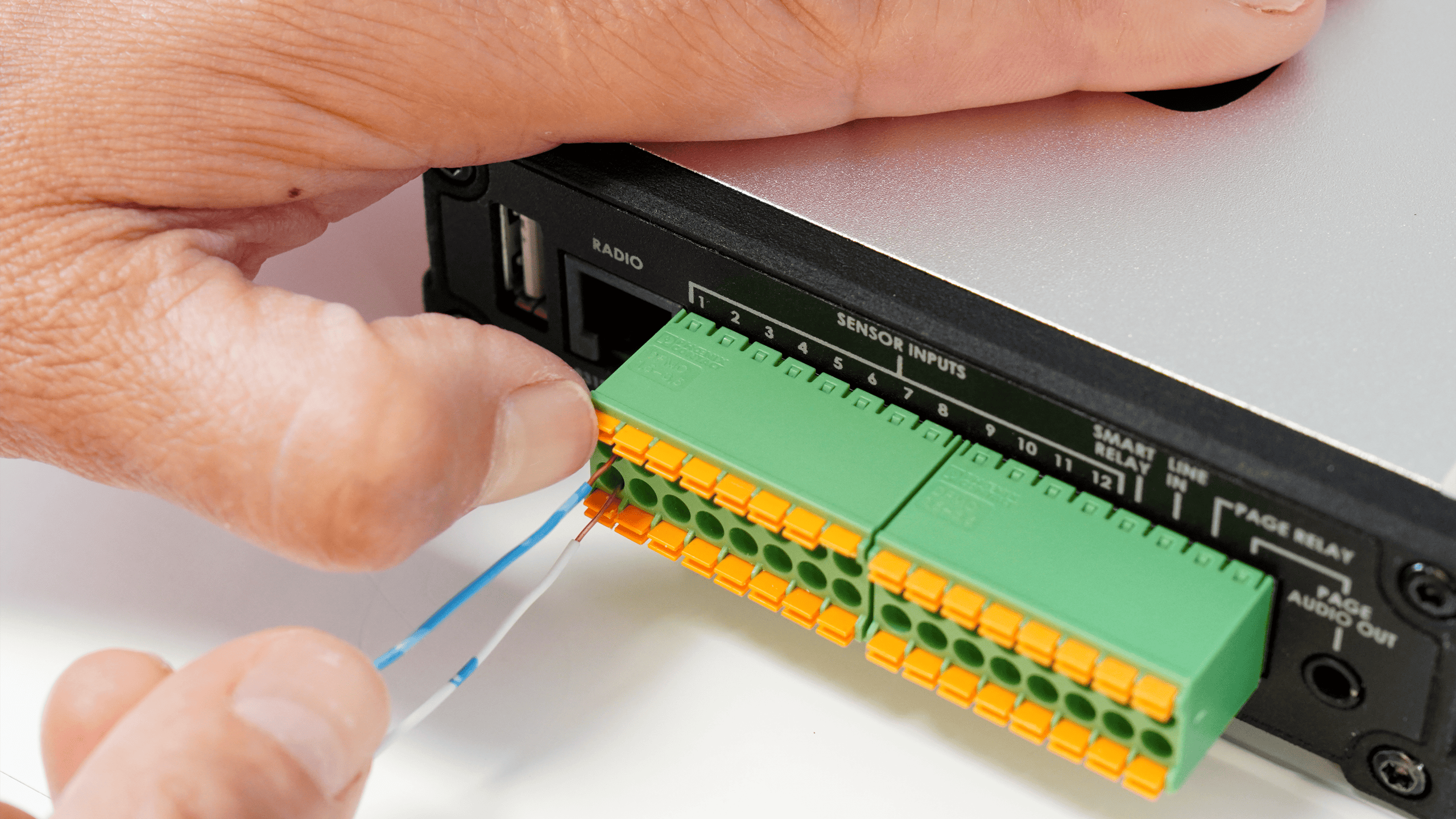
Release the orange button, then gently pull on the wire to verify that it is securely locked in place.
Repeat steps 5 and 6 to connect the other conductor of the single twisted-pair to the bottom terminal.
Related Links:
Compatible Algo Input Devices
The following Algo devices can be the SMART RELAY-compatible input devices.
1202 Call Button
Connect the center contacts of the modular connector on the back of the 1202 to the SMART RELAY terminal block (not polarity-sensitive) on the 8312.
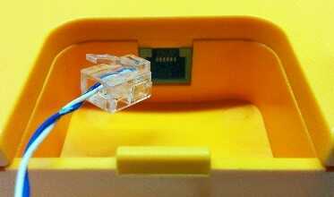
1203 Call Switch
Connect a single twisted-pair (24 AWG) from the device's terminal block to the SMART RELAY terminal block (not polarity-sensitive) on the 8312.
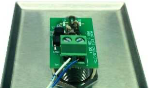
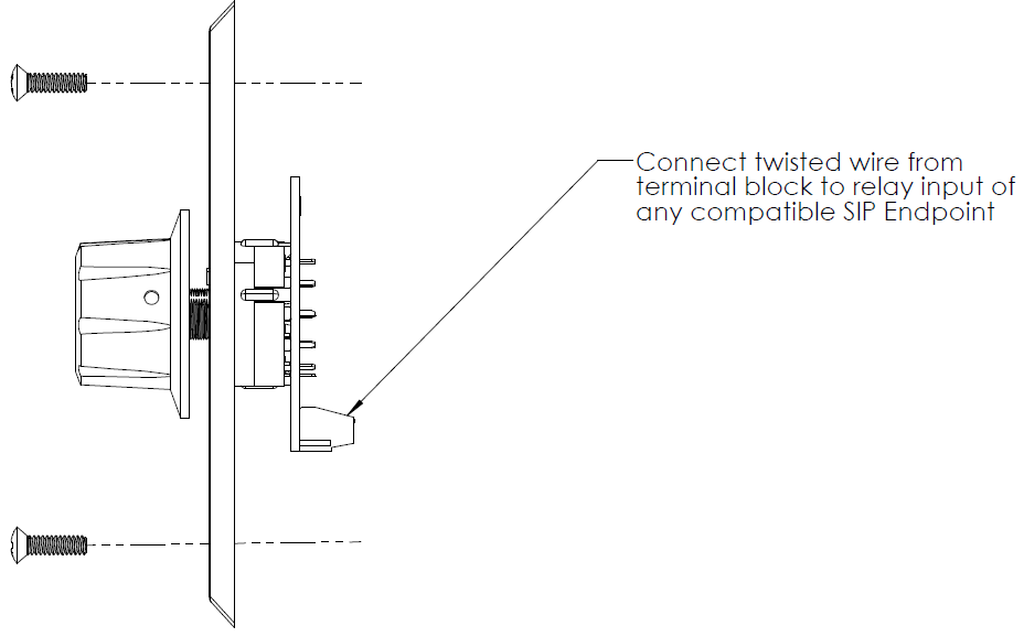
1204 Volume Control Switch
Connect a single twisted-pair (24 AWG) from the device's terminal block to the SMART RELAY terminal block (not polarity-sensitive) on the 8312.
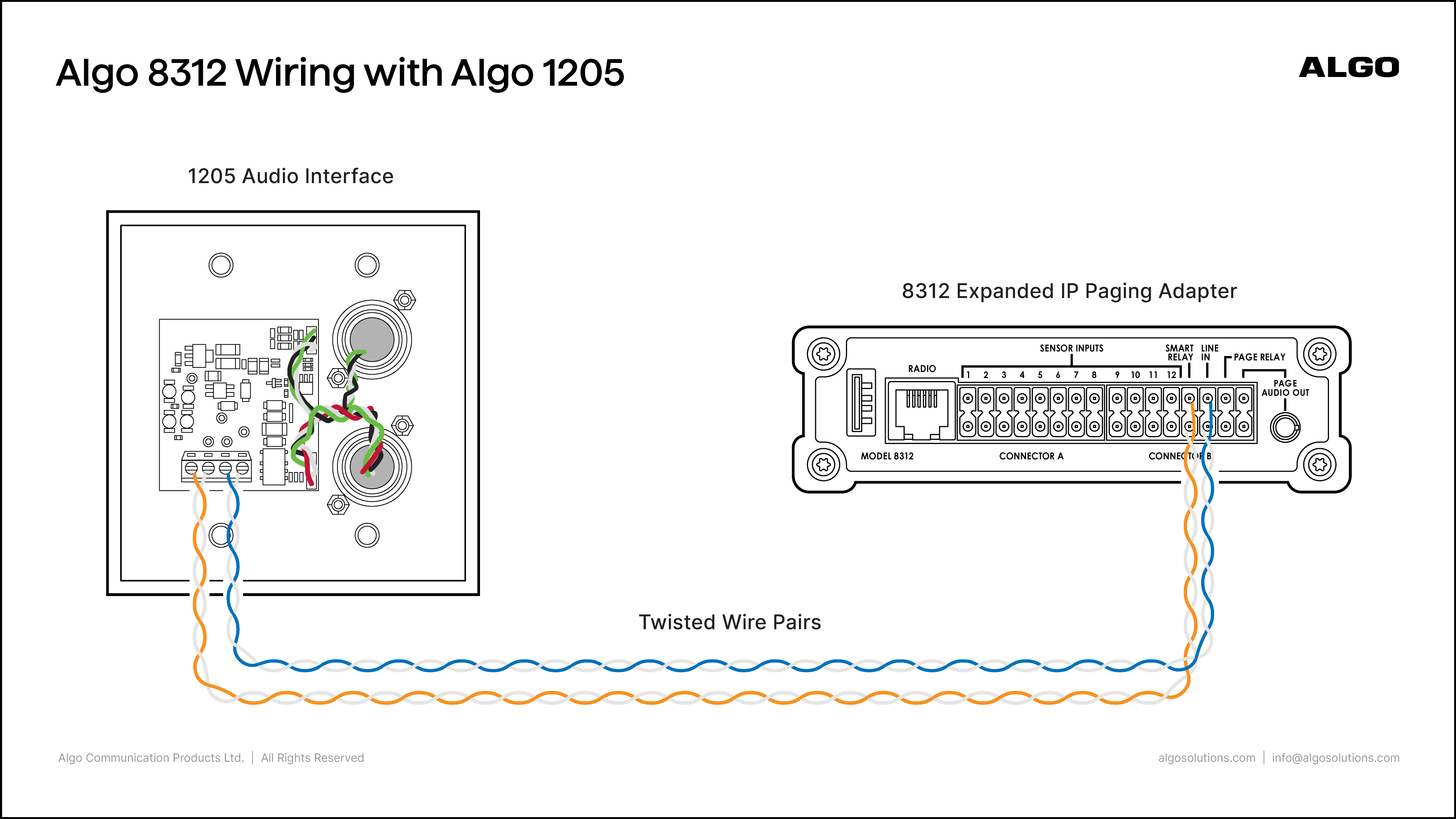
1205 Audio Interface
Two pairs of wires connect the 1205 Audio Interface to the 8312. One pair carries balanced audio, and the other communicates the rotary switch position.
To connect a 1205 to the 8312:
Connect the Relay Input switch terminals (not polarity-sensitive) on the 1205 to the SMART RELAY terminal block on the 8312.
Connect the Line In audio terminals (not polarity-sensitive) on the 1205 to the LINE IN terminals on the 8312.
Algo 2507 Ring Detector
Connect a single twisted-pair (24 AWG) from the device's terminal block to the SMART RELAY terminal block (not polarity-sensitive) on the 8312.
.png)
Connect a single twisted-pair (24 AWG) from the 1211/1212's terminal block to the SMART RELAY terminal block (not polarity-sensitive) on the 8312.
Wiring an Output Device to the Relay Output
The PAGE RELAY terminals provide a dry contact closure when triggered.
You can connect an external device that is activated by opening or closing a circuit, such as a strobe light, door strike, magnetic lock, or other relay-controlled equipment.
To wire an output device to the Relay Output:
Disconnect power from the external device, if applicable.
Connect the control wires (AWG 24) from the external device to the PAGE RELAY terminals (not polarity-sensitive) on the 8312.
Restore power to the external device, if applicable.
Related Links:
Using Loud Ringing
You can set up SIP extensions for loud ringing. The Algo 8312 will detect incoming SIP ring events on this extension and play an alert tone (and send a multicast if enabled) for as long as the call is ringing. It will not answer the call. This allows the phone’s ring to be heard clearly, even in a noisy environment. Often, the 8312 will be part of a hunt group or ring group to ring in conjunction with a telephone.
To play a tone for incoming SIP rings:
Go to Basic Settings → SIP.
Enter the SIP server IP address or domain name in SIP Domain (Proxy Server).
Set Ring/Alert Mode to Monitor "Ring" event on registered SIP extension.
Configure the following:
Ring Extension
Authentication ID
Note that some SIP servers may say Username instead of Authentication ID.
Authentication Password
Configure Audio Output:
Page Audio Output: Sends the audio to the PAGE AUDIO OUT and AUX OUT interfaces.
Radio Audio Output: Sends the audio to RADIO and AUX OUT interfaces.
Both: Sends the audio to PAGE AUDIO OUT, RADIO, and AUX OUT interfaces.
Select Save.
Go to Basic Settings → Features and configure Inbound Ring Settings:
Ring/Alert Tone: Select an audio file to play for inbound ring calls.
Ring/Alert Volume: Set the playback volume. The volume increases from -5 to 10.
Ring Limit: Specify the duration of the audio file playback.
Select Save.
Go to the Status tab and make sure that the Ring extension registration is successful.
.png)
Call this Ring Extension from a device or application that supports SIP calling.
8312 detects the ring signal, plays the configured Ring/Alert Tone and multicasts it (if configured).
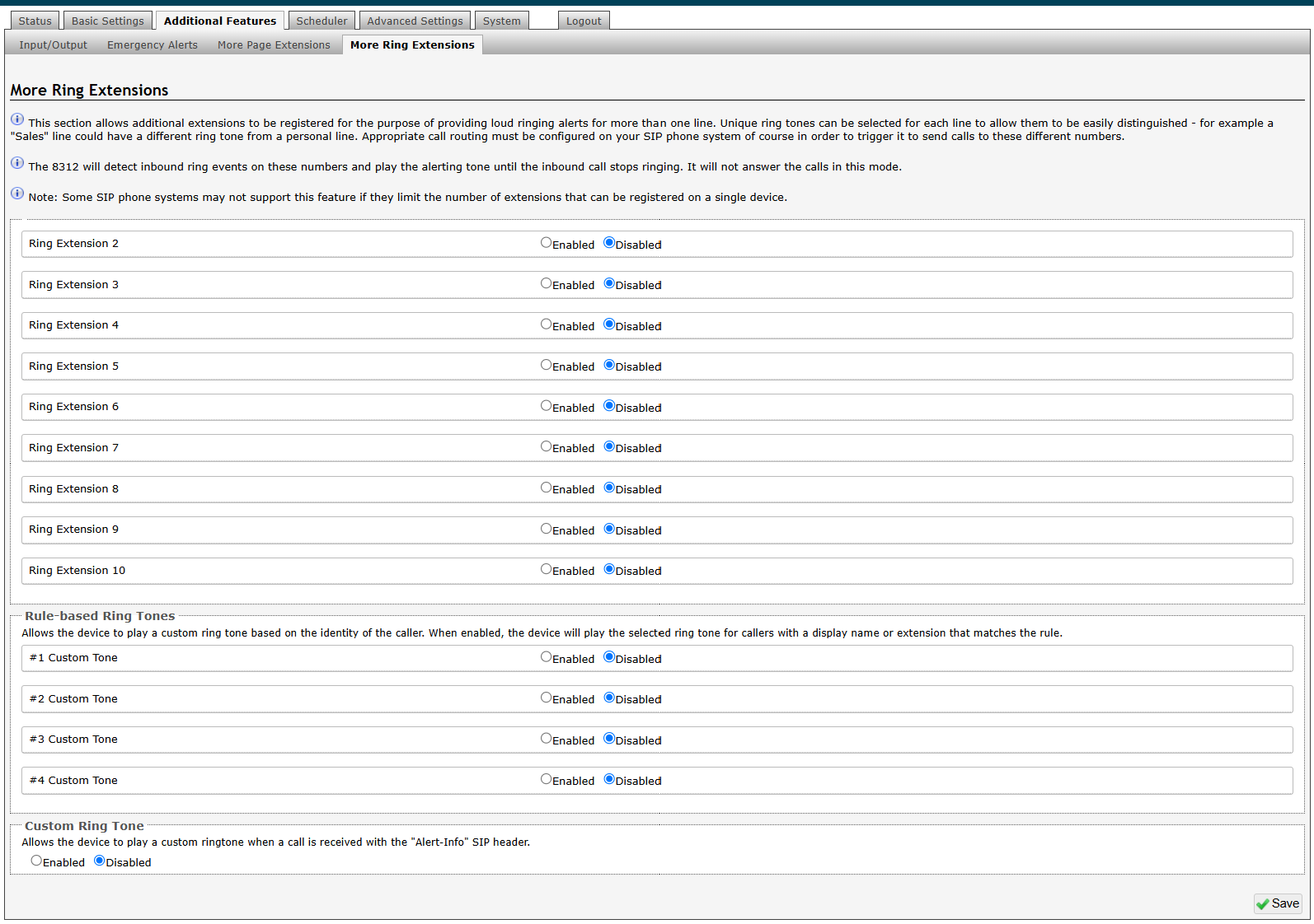
Configuring Additional Ring Extensions
Configure additional ring extensions to support different incoming ring events, such as loud ringing. Using more ring extensions allows different ringtones to be played for each unique extension to identify which extension is ringing.
Up to 10 SIP ring extensions can be registered.
Note
Ring tones associated with Additional Ring Extensions are output only through the PAGE AUDIO OUT interfaces (terminal block and 3.5 mm jack) and AUX OUT.
Note
Ring extensions should not be used for emergency alerts, as emergency notifications are intended to play continuously until manually stopped.
For emergency alerts, see the Emergency Alerts.
To configure additional ring extensions:
Go to Additional Features → More Ring Extensions.
Select Enabled beside the extension of interest.
Enter the following information. This information will be available from your IT Administrator.
Extension
Authentication ID
Authentication Password
Display name (Optional)
Select a Ring Tone.
If you select <Use Default Ring Tone>, the tone specified in Basic Settings → Features → Inbound Ring Settings → Ring/Alert Tone plays.
Select Save.
When the Ring Extension is dialed, the Ring Tone is played on the PAGE AUDIO OUT (terminal block and 3.5 mm jack) and AUX OUT interfaces.
Related Links:
Using Rule-Based Ringtones
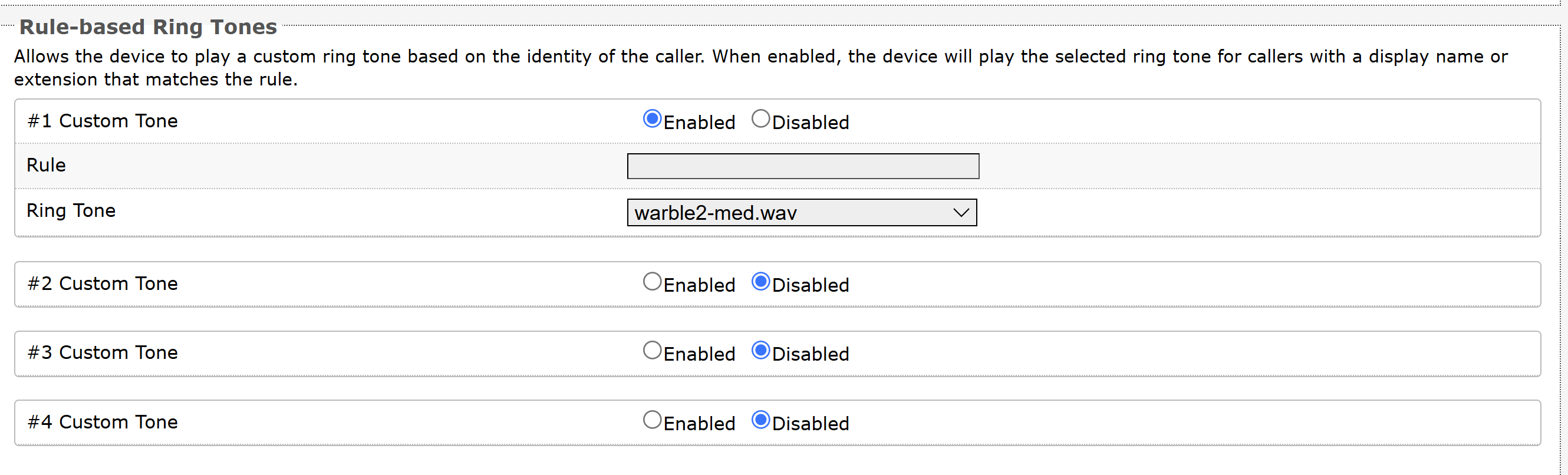
Set a rule-based ringtone for the device to play a custom ringtone based on the caller's identity. When enabled, the device will play the selected ringtone for callers with a display name or extension that matches the rule.
Note
Rules are tested starting at #1 Custom Tone, so the first rule to match determines the ring tone file that is played. If no rules match, then the default tone in Basic Settings → Ring is played.
To configure rule-based ringtones:
Go to Additional Features → More Ring Extensions.
Go to the Rule-Based Ringtone section and select Enabled beside a custom tone.
Enter the following information:
Use a Regular Expression (regex) to set the Rule.
^means that the text must be at the beginning of the Caller ID string. So^Group1matches all strings that start with the textGroup1(e.g.,Group1 555-123-4567).$means that the text must be at the end of the Caller ID string. So$123matches all strings that end with123(e.g.,Steve123).For an exact match, use both of the above. Thus,
^Steve$matches only the stringSteve.If none of the special characters above are used, then it will match the text anywhere in the string. So a rule of just
Stevewill match both123 SteveandSteve 123.For a default case, use
.*which matches everything (any number of any characters), including blank.
Select a Ring Tone to play for calls from callers matching the specified rule.
Select Save.
Using Custom Ringtones
You can enable a custom ring to play a custom ringtone when receiving calls with the Alert-Info SIP header.
To enable custom ringtones:
Go to Additional Features → More Ring Extensions.
Go to the Custom Ring Tone section and select Enabled.
SIP Paging
The 8312 supports SIP-based voice paging for both single-device and multi-endpoint deployments. When configured with a SIP extension, the 8312 can receive live voice pages from a telephone, SIP client, or other device. For larger deployments, the 8312 can also act as a multicast transmitter, allowing one SIP-registered adapter to stream audio to multiple Algo IP endpoints without requiring each receiver to register individually with the SIP server.
Related Links:
Additional configurations
If VLAN is used, navigate to the Advanced Settings → Network tab to set VLAN options. Once the device is using VLAN you will need to be on the same VLAN to access the web interface.
Additional configurations can be made to meet the needs of the environment. This includes:
Enabling the G.722 audio code for increased speech intelligibility.
Enabling ambient noise monitoring for the speaker volume to automatically adjust based on background noise.
Enabling talkback to allow those near the speaker to communicate with the caller.
SIP Calling to a Single Device
A common application of the 8312 is voice paging via SIP. SIP allows Algo IP products to register with most hosted/cloud or on-premise telephone systems to broadcast voice messages to multiple IP endpoints over a network in real-time.
You can activate the 8312 by dialing its assigned SIP extension from a telephone, device, or client. The device will auto-answer, play the default pre-announce tone, and allow voice paging until disconnected.
To configure your SIP paging settings:
Go to Basic Settings → SIP.
Enter the SIP server IP address or domain name in SIP Domain (Proxy Server).
Enter a Page Extension and its credentials:
Authentication ID
Authentication Password
Note that some SIP servers may say Username instead of Authentication ID.
Display Name
Configure Audio Output:
Page Audio Output: Sends audio to the AUX OUT and PAGE AUDIO OUT interfaces.
Radio Audio Output: Sends audio to the RADIO and AUX OUT interfaces.
Both: Sends audio to the PAGE AUDIO OUT, RADIO, and AUX OUT interfaces.
Go to Basic Settings → Features and configure Inbound Page Settings.
Go to the Status tab and make sure that the Page registration is successful.
.png)
Dial the assigned extension from a telephone, device, or client.
The 8312 will auto-answer, play the default pre-announce tone, and allow voice paging until disconnected.
Related Links:
Configuring Additional Page Extensions
Using more page extensions is an alternative way to select several different multicast zones to page to when the device is configured as a multicast transmitter.
Additional SIP page extensions can be registered for each multicast zone. This enables you to dial a zone directly without entering DTMF codes; however, this may require additional SIP licenses depending on the SIP provider. Some SIP telephone systems may not support this capability or have a limit on the number of extensions registered on a single device.
Some considerations when choosing to use multiple extensions over DTMF include:
DTMF (One Extension) | Multiple Extensions |
Pros:
Cons:
| Pros
Cons
|
Note
Audio from SIP calls using Additional Page Extensions is output only through the PAGE AUDIO OUT interfaces (terminal block and 3.5 mm jack) and AUX OUT.
To configure additional page extensions:
Go to Additional Features → More Page Extensions.
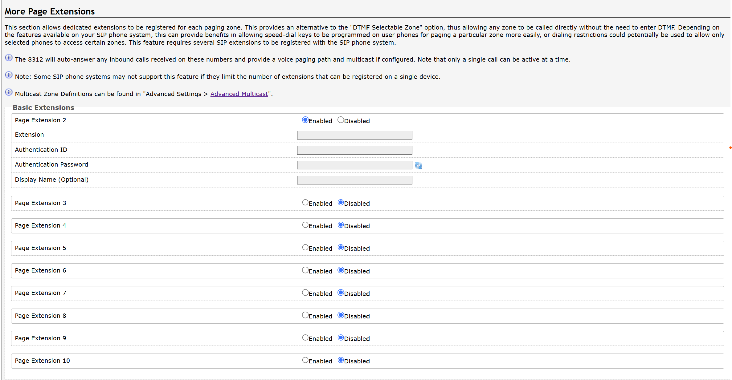
Select Enabled beside the extension of interest.
Enter the following information. This information will be available from your IT Administrator.
Extension
Authentication ID
Authentication Password
Display Name (Optional)
Select Save.
The device will auto-answer any inbound calls received on these numbers, establish a voice paging path, and multicast audio to the associated transmit zone if configured. Only a single call can be active at a time.
Related Links:
Emergency Alerts
Your device can be used for alerting in the case of emergency (e.g., lockdown, evacuation, reverse evacuation), safety (e.g., medical, workplace accident), and security events (e.g., OSHA or similar workplace regulations).
Emergency alerts allow you to quickly broadcast prerecorded announcements to local outputs and multicast receivers during emergency situations.
Note
Emergency announcements are output through the following local interfaces:
PAGE AUDIO OUT
AUX OUT
If the device is configured as a multicast transmitter, the announcements are also transmitted via multicast to the configured receiver devices.
You trigger emergency alerts using one of the following ways:
Direct Extension: Dial the extension associated with the desired emergency announcement.
DTMF Selectable: Dial the Extension for DTMF Selection. After the call connects, enter the desired announcement ID using DTMF tones.
Follow these steps to configure and use emergency alerts:
Configure how emergency alerts are triggered:
Configuring Direct Extensions for Emergency Alerts
You can dial a pre-configured extension number to trigger and play an emergency alert continuously. Up to 10 extensions can be registered, allowing up to 10 different announcements.
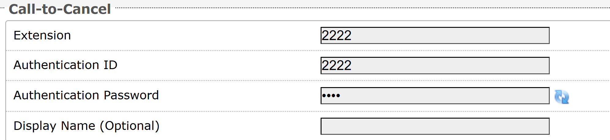
A single Call-to-Cancel extension also needs to be registered. Calling this number will cancel an active announcement.
To configure direct extensions for emergency alerts:
Go to Additional Features → Emergency Alerts.
Configure general Settings:
Default Announcement Duration: An announcement can be played once or continuously until cancelled.
Play Once: Plays the selected audio file once.
Play Until Cancelled: Plays the announcement continuously until the Call-to-Cancel extension is dialed or until the Default Maximum Announcement Time is reached.
Default Maximum Announcement Time: Select the maximum time an announcement will play for.
Set Announcement Selection Mode to Direct Extensions.
Configure Answer Inbound Call.
Enabled: Answers the inbound call automatically and provides the option to play a confirmation tone before starting the alert, then automatically release the call.
The auto-answering option can be useful when the caller cannot hear the announcement from their location. However, in instances where the call might go to a group/multiple extension(s) (including this device), the auto-answer may intercept that call and prevent it from ringing on other devices.
Disabled: Detects the inbound ring signal without answering the call.
In some cases, keeping this setting disabled may be useful if the extension is part of a ring group. This will prevent interference with other calls or configurations, such as loud ringing or other alerting.
If you have enabled Answer Inbound Call, select whether to configure a passcode to prevent unintentional announcements:
Announcement Passcode: Enter a passcode that a caller must enter to play or cancel an announcement.
The passcode must contain only digits and can be up to 15 digits long. When prompted, the caller must enter the passcode followed by the # sign before the announcement will be played or cancelled. The passcode prompt will be played before any other action. If the passcode is not correctly entered within 15 seconds, the call will end, and there will be no change to the current announcement state.
Passcode Prompt Tone: Select a tone to play when the passcode is ready to be entered.
Configure a Call-to-Cancel extension.
Select Save.
Related Links:
Configuring DTMF Extensions for Emergency Alerts
You can dial a single DTMF extension, enter the desired announcement ID using DTMF tones.
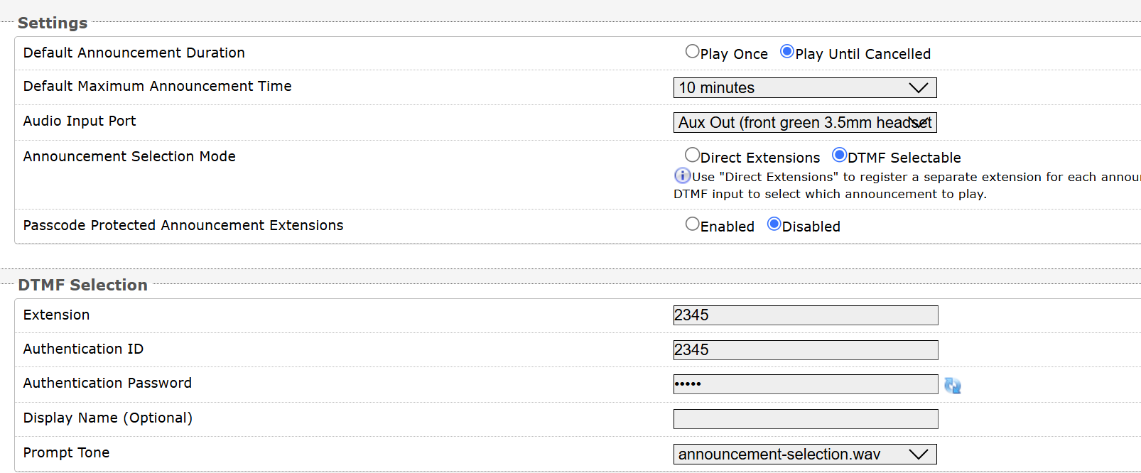
To configure a DTMF extension for emergency alerts:
Go to Additional Features → Emergency Alerts.
Configure general Settings:
Default Announcement Duration: An announcement can be played once or continuously until cancelled.
Play Once: Plays the selected audio file once.
Play Until Cancelled: Plays the announcement continuously until the Call-to-Cancel extension is dialed or a timeout is reached.
Default Maximum Announcement Time: Select the maximum time an announcement will play for.
Set Announcement Selection Mode to DTMF Selectable.
Select whether to configure a passcode to prevent unintentional announcements:
Announcement Passcode: Enter a passcode that a caller must enter to play or cancel an announcement.
The passcode must contain only digits and can be up to 15 digits long.
When prompted, the caller must enter the passcode followed by the # sign before the announcement will be played or cancelled. The passcode prompt will be played before any other action. If the passcode is not correctly entered within 15 seconds, the call will end, and there will be no change to the current announcement state.
Passcode Prompt Tone: Select a tone to play when the passcode is ready to be entered.
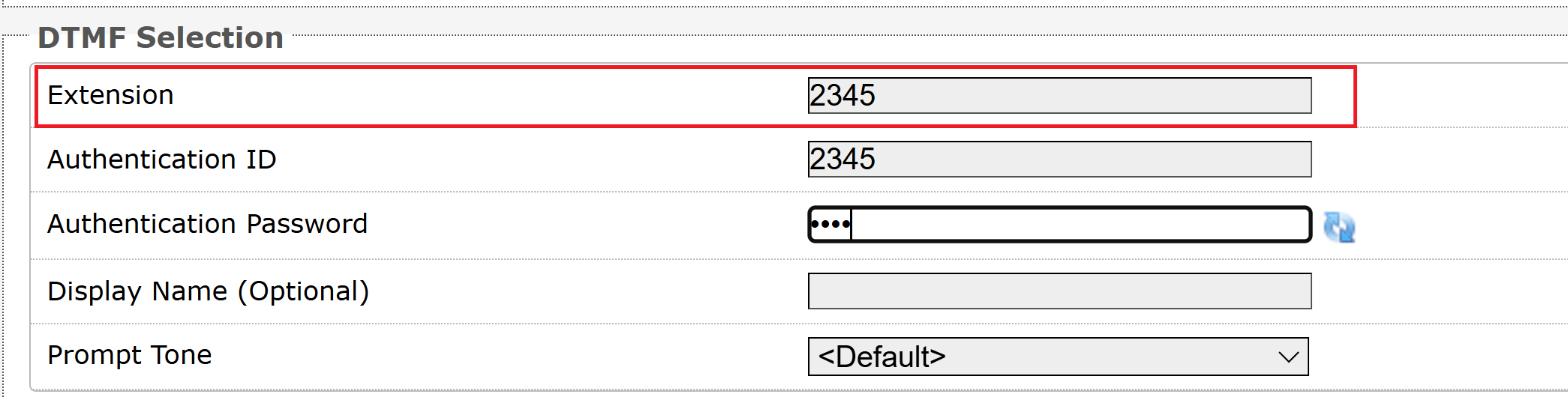
Configure DTMF Selection:
Extension
Authentication ID
Authentication Password
Display Name (Optional)
Prompt Tone
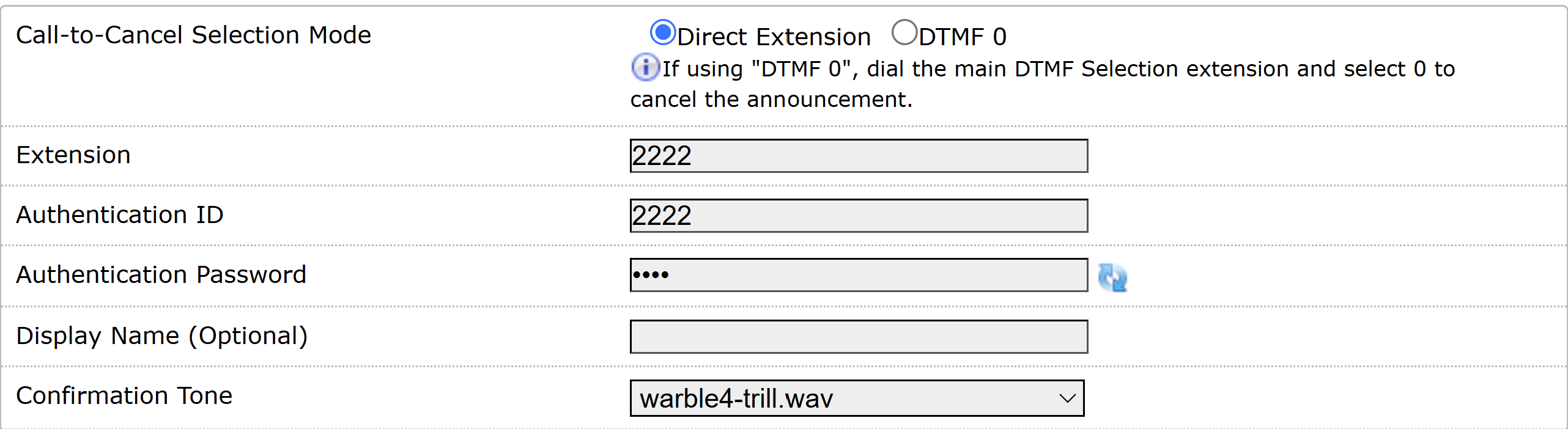
Configure a Call-to-Cancel extension:
Call-to-Cancel Selection Mode:
Direct Extension: Configure a direct extension.
DTMF 0: Dial the DTMF Selection extension. After the call connects, dial
0using DTMF tones to cancel the announcement.
Select Save.
Configuring Emergency Announcements
Configure how the selected emergency announcement is played, including its playback duration, audio source, multicast destination, and optional REST API requests that are sent when the announcement starts or completes.
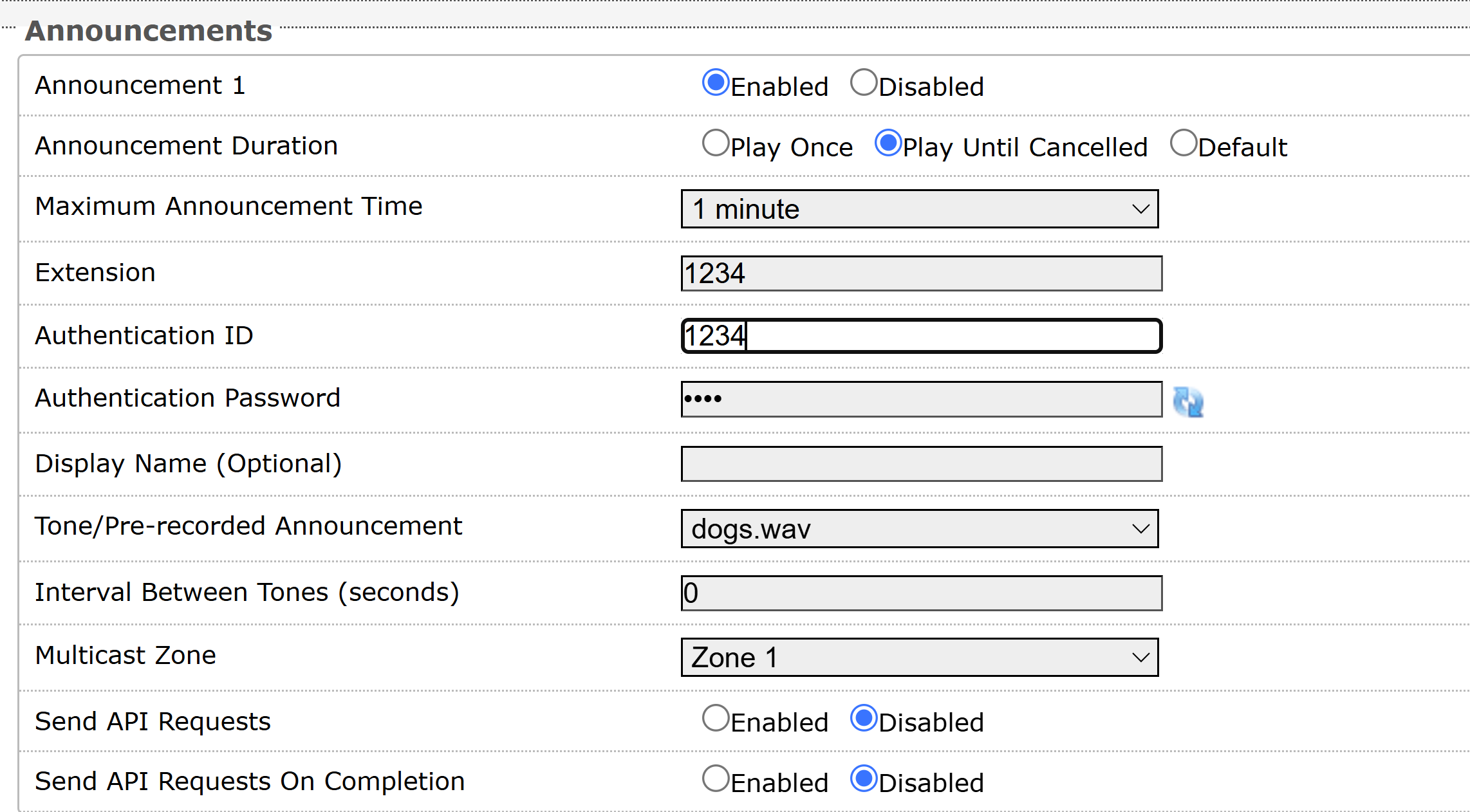
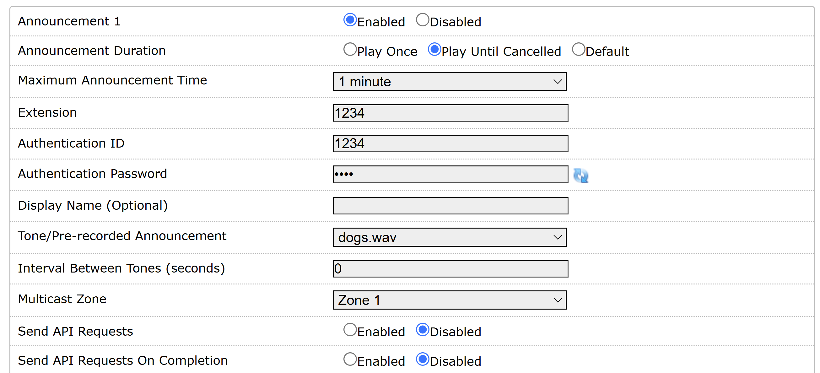
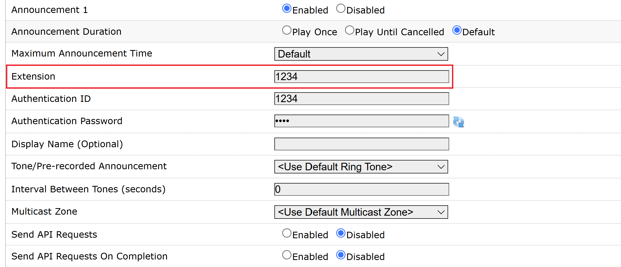
To configure an Emergency Announcement:
Go to Additional Features → Emergency Alerts → Announcements.
Set the desired Announcement to Enabled.
Configure the following:
Announcement Duration:
Play Once: Plays the selected audio file once.
Play Until Cancelled: Plays the announcement continuously until the Call-to-Cancel extension is dialed or the Maximum Announcement Time is reached.
Default: Uses the value configured for Default Announcement Duration.
Maximum Announcement Time: Select the maximum announcement time.
Extension: Specify the announcement extension.
This option is available only when the Announcement Selection Mode is set to Direct Extensions.
Tone/prerecorded Announcement: Select a file or audio input to use as the announcement:
<Use Audio Input Port>: Use the audio input specified in Additional Features → Features → Emergency Alerts → Settings → Audio Input Port.
<Use Default Ringtone>: Use the ringtone specified in Basic Settings → Features → Ring/Alert Tone.
Interval Between Tones (seconds): Specify the interval between tone playbacks, in seconds.
Confirmation Tone: Select a file to use as a confirmation tone.
This option is available when Answer Inbound Call is enabled.
Multicast Zone: Set the RTP multicast zone where announcements will be played.
Multicast Poly Group: Set the Poly Group where announcements will be played.
This option is available only when your Multicast Type is set to one of the following:
Poly Group Page
Poly Push-to-Talk
Regular RTP + Poly Group Page
Regular RTP + Poly Push-to-Talk
To send REST API requests to external devices or systems when the announcement starts, enable and configure Send API Requests.
To send REST API requests to external devices or systems when the announcement completes, enable and configure Send API Requests On Completion.
Select Save.
Triggering Emergency Alerts
You can trigger an emergency alert using one of the following announcement selection modes:
Direct Extension: Dial the configured Extension assigned to the desired emergency announcement.
DTMF Selectable: Dial the Extension configured for DTMF Selection. After the call is connected, enter the desired announcement ID using DTMF tones.
To trigger an emergency alert using an extension:
Do one of the following:
If you are using Direct Extensions as the Announcement Selection Mode, dial the configured Extension assigned to the desired emergency announcement.
If you are using DTMF Selectable as the Announcement Selection Mode, dial the Extension configured for DTMF Selection.
If an Announcement Passcode is configured, enter the passcode followed by the # sign after hearing the Passcode Prompt Tone.
If the passcode is not correctly entered within 15 seconds, the call will be ended.
For DTMF Selectable mode, after the call is connected, enter the desired announcement ID using DTMF tones.
For example, for Announcement 5, enter 5.
The configured announcement plays locally and/or via multicast (if your device is configured as a Multicast Transmitter (Sender)).
To cancel the announcement, dial the Call-to-Cancel extension.
Otherwise, the announcement plays until the Maximum Announcement Time is reached.
If an Announcement Passcode is configured, enter the passcode followed by the # sign after hearing the Passcode Prompt Tone.
Related Links:
Announcement and DTMF Extension Mapping
The announcement is selected according to the following mapping:
Announcement | DTMF Key |
|---|---|
Announcement 1–9 | 1–9 (direct mapping) |
Announcement 10 | 0 |
Note
If Call-to-Cancel Selection Mode is configured to use DTMF 0, Announcement 10 is unavailable because the 0 key is reserved for canceling the announcement.
In this configuration, only Announcements 1–9 are available.
Multicast Paging
The 8312 can be programmed as a multicast transmitter or receiver and can be grouped into up to 50 multicast zones. Multicast allows a single transmitting device to simultaneously stream audio to multiple receiving devices over the network. To optimize the use of a single SIP extension, the 8312 can be used as a multicast transmitter to stream audio to other Algo receiver devices. Any number and combination of Algo Speakers, Paging Adapters, IP Displays, or Visual Alerters can be set as receiving devices. Receiving devices do not require a unique SIP extension and, therefore, do not need to be registered with the SIP server.
In large environments, it is recommended that the device configured as the multicast sender be stored securely to mitigate the risk of interference or damage. The 8312 is most often used in these scenarios. In a smaller environment or when needed, the 8312 or other devices can also be configured as the multicast sender.
Key Configurations for Multicast Transmitters and Receivers
Ensure the following settings are correctly configured and consistent between the transmitter and receiver devices. These settings depend on your Multicast Mode setup:
Multicast Mode (under Basic Settings → Multicast)
Sender: Set to Transmitter
Receiver: Set to Receiver
Multicast Type (under Basic Settings → Multicast)
Both Sender and Receiver should be set to the same Multicast Type. Normally, it’s Regular (RTP) unless Poly devices are involved.
Zone Number (under Basic Settings → Multicast)
Confirm the Transmitter Single Zone selected on the Transmitter is also enabled under the Basic Receiver Zones on the Receiver.
Zone Definitions (under Advanced Settings → Advanced Multicast)
Verify that the IP Address and Port Number for the multicast zone match exactly on both the Transmitter and Receiver devices.
Configuring Your Device as a Multicast Transmitter
The Algo IP endpoint configured as the transmitter will stream audio to all of the receivers simultaneously. Receiver endpoints do not require SIP extensions and do not need to register with the SIP Communication Server.
The page pre-announce tone is generated from the transmitter. The speaker volume can be increased or decreased for each multicast receiver individually.
Note
Always ensure that the multicast settings on all receiver devices match those of the transmitter.
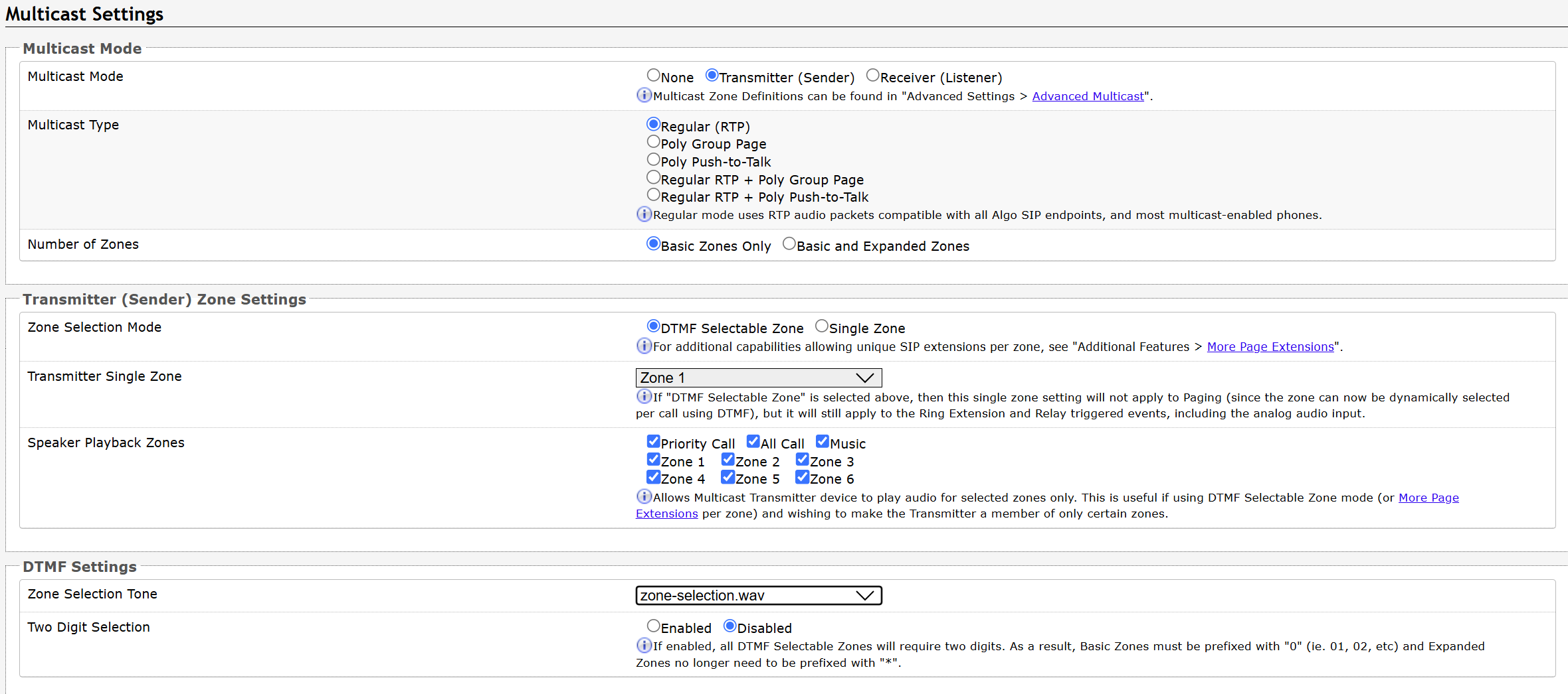
To configure your device as a Multicast Transmitter:
Go to the Basic Settings → Multicast.
Configure Multicast Mode settings:
Multicast Mode: Set to Transmitter (Sender).
Multicast Type: Select an option.
Regular (RTP): Multicasts only to Algo IP endpoints or multicast-enabled phones.
Poly Group Page or Poly Push-to-Talk: Multicasts to Poly phones.
Regular RTP + Poly Group Page or Regular RTP + Push-to-Talk: Multicasts to Poly phones, Algo IP endpoints, and multicast-enabled phones.
Note
Make sure your multicast receivers be set to the same Multicast Type. Normally, it’s Regular (RTP) unless Poly devices are involved.
Number of Zones:
Basic Zones Only: Uses nine or fewer multicast zones.
Basic and Expanded Zones: Uses up to 50 zones. The expanded zones have the same behavior as the basic Receiver zones but are hidden by default to simplify the interface.
Configure Transmitter (Sender) Zone Settings:
Zone Selection Mode:
Single Zone: Broadcasts on one pre-configured zone. Multiple SIP extensions can be registered on the Transmitter device. Each extension is mapped to a unique zone, allowing zones to be called directly (e.g., from speed-dial keys).
DTMF Selectable Zone: Selects the zone by the DTMF key.
Transmitter Single Zone: Selects the default zone for the multicast stream to be sent to.
Note
If the DTMF Selectable Zone is chosen, this single zone setting will not apply to Paging since the zone will be dynamically selected per call using DTMF. However, this single zone setting will still apply to the ring extension and relay triggered events.
When you configure the multicast receivers, make sure this zone is selected in the Basic Receiver Zones .
Speaker Playback Zones: Specifies which basic zones the device can play audio.
Expanded Speaker Playback Zones: Specifies which expanded zones the device can play audio.
If your Multicast Mode includes Poly Group Page or Poly Push-to-Talk, configure also the following:
Poly Zone: Enter the same Multicast IP Address and Port number configured on the Poly phones.
Poly Group Selection Mode:
Single Group: Broadcasts on one pre-configured group. Multiple SIP extensions can be registered on the Transmitter device. Each extension is mapped to a unique group, allowing groups to be called directly (e.g., from speed-dial keys).
DTMF Selectable Group: Selects the group by the DTMF key.
Poly Default Channel: Selects the default group for the multicast stream to be sent to.
The Poly Default Channel is the default channel used for multicast actions unless an option is available for a custom channel with specific parameters.
Note
If DTMF Selectable Group is chosen, this single group setting will not apply to paging since the group will be dynamically selected per call using DTMF. The Single Group setting will still apply to the ring extension and relay triggered events.
Speaker Playback Groups: Selects Speaker Playback Groups to control which specific groups can play audio from the device.
This is useful if using the DTMF Selectable Group mode or additional page extensions (Additional Features → More Page Extensions) per group to make the device a member of only certain zones. In this case, the Transmitter does not participate in the Zone but transmits certain traffic.
If your Poly Group Selection Mode is set to DTMF Selectable Zone or DTMF Selectable Group, configure how to use the DTMF keys:
Zone Selection Tone: Select a tone to be played to prompt a user to select a zone to multicast to.
This may be used as an interactive voice response (IVR) menu by uploading a custom audio file in the tones folder through System → File Manager. Each zone may use a different tone. This can be configured in Advanced Settings → Advanced Multicast.
Two Digit Selection: When enabled, all DTMF Selectable Zones will require two digits. As a result, Basic Zones and Poly group 1-9 must be prefixed with 0, and Expanded Zones or Poly Group 10-25 will no longer need to be prefixed with
*.
Select Save.
Configuring Your Device as a Multicast Receiver
Configure your device as a multicast receiver to play multicast audio streams transmitted by another multicast-enabled device. In receiver mode, the device listens for multicast traffic on one or more configured zones and automatically plays paging announcements, emergency alerts, scheduled bells, background music, or other multicast audio without requiring its own SIP registration.
This allows a single transmitter to distribute audio simultaneously to many receivers while minimizing SIP licenses, network bandwidth, and system complexity. Each receiver uses its own local playback volume settings independently of the transmitter.
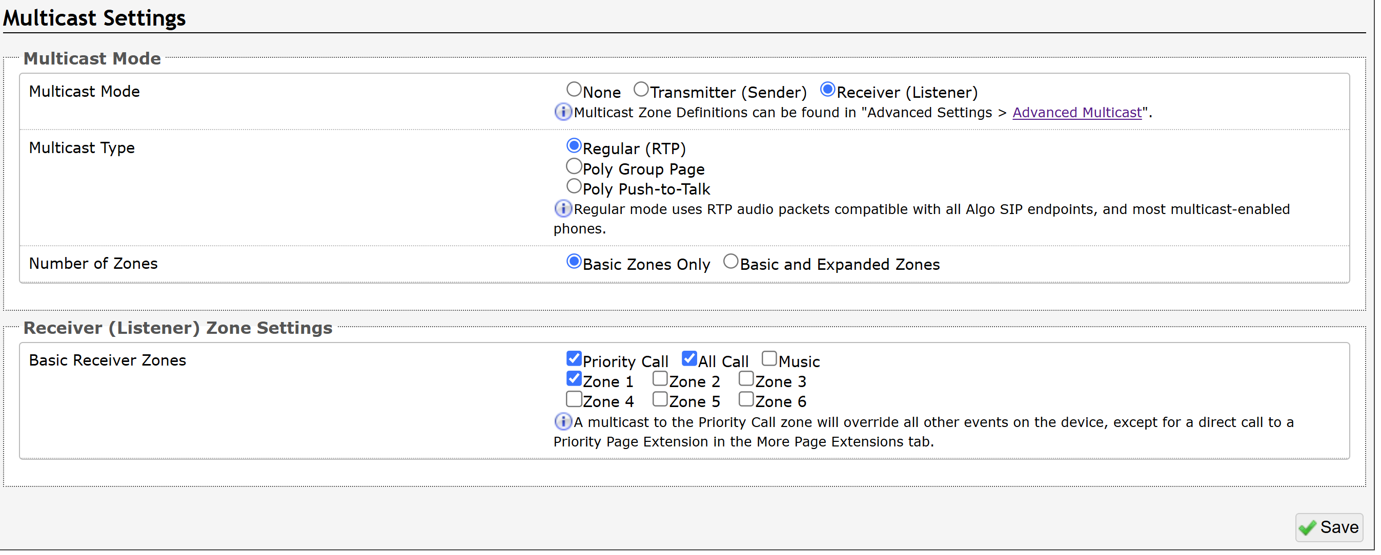
To configure your device as a Multicast Receiver:
Go to the Basic Settings → Multicast.
Configure Multicast Mode settings:
Multicast Mode: Set to Receiver (Listener).
Multicast Type: Select an option.
Note
Make sure you select the same Multicast Type as your Multicast Transmitter (Sender).
Regular (RTP): All multicast receivers are Algo endpoints. The device will listen to the selected Basic Receiver Zones or Expanded Receiver Zones.
The zone IP addresses are defined in Advanced Settings → Advanced Multicast.
Poly Group Page or Poly Push-to-Talk: There are Poly phones in the multicast. The device will listen to selected Poly Channels.
The Poly Group IP address is specified in Poly Zone.
Specify the zone or Poly Group settings:
Note
Make sure you select the same zones/channels as your Multicast Transmitter (Sender).
Select Zones:
Basic Receiver Zones: Select the desired basic zones.
Expanded Receiver Zones: Select desired expanded zones, if available.
Note
Make sure the Receiver Zones include the Transmitter Single Zone selected on your Transmitter device.
Select Poly groups:
Poly Zone: Enter the same Multicast IP Address and Port number configured on the Poly phones.
Poly Receiver Channels: Select the desired channels.
Select Save.
Configuring Multicast Zones
Each 8312 has a unique IP address and shares a common multicast IP and port number (multicast zone) for multicast packets. The transmitter units send to a configurable multicast zone, and the Receiver units listen to assigned multicast zones.
The network switches and router see the packet and deliver it to all the zone members. The multicast IP and port number must be the same on all transmitter and receiver units of the same zone. The user may define multiple zones by picking different multicast IP addresses and/or port numbers.
Multicast IP addresses range: 224.0.0.0/4 (from 224.0.0.0 to 239.255.255.255).
Port numbers range: 1 to 65535.
By default, all Algo devices are set to use the multicast IP address 224.0.2.60 and the port numbers 50000-50008.
Note
Ensure the multicast IP address and port number do not conflict with other services and devices on the same network.
Make sure that the IP Address and Port Number for the multicast zone match exactly on both the Transmitter and Receiver devices.
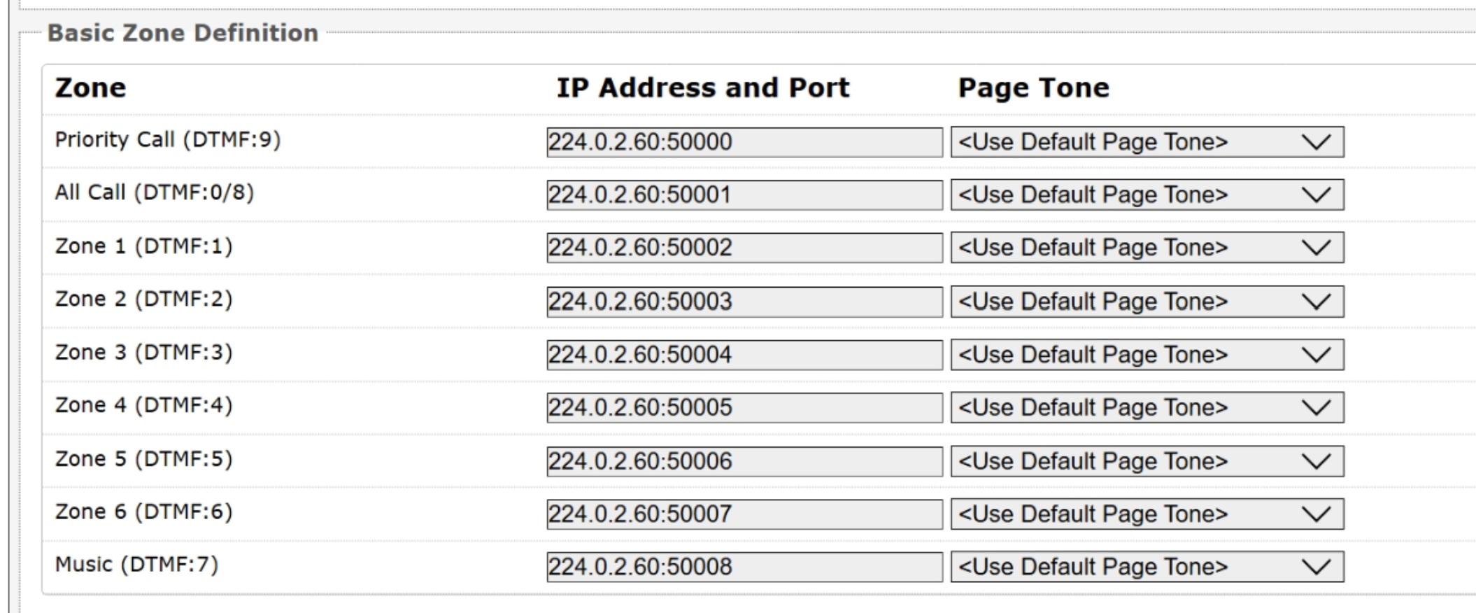
Notes
Ensure the IP Address and Port # match on both the Transmitter (Sender) and Receiver (Listener), for the zone being used.
To configure Multicast zones:
Log in to the web interface of your multicast transmitter or receiver device.
Go to Advanced Settings → Advanced Multicast.
View the default zone IP Address and Port. Edit it if necessary.
To specify a different tone to play before the multicast starts, select an audio file from the Page Tone drop-down list.
If you select <Use Default Page Tone>, the audio file specified under Basic Settings → Features → Inbound Page Settings → Page Tone plays.
Select Save.
Multicast Page Zones
By default, the 8312 can listen to nine basic multicast zones; however, up to 50 are available (See Additional Features → More Page Extensions for more details). The multicast IP addresses define these zones.
By default, these zones have the names below, but can be used however you prefer:
Priority
All Call
Zone 1
Zone 2
Zone 3
Zone 4
Zone 5
Zone 6
Music
Multicast Page Zone Priority
When set as a multicast receiver, zones have a priority hierarchy where zones higher on the list will be treated with higher priority, with Music being the lowest priority. When set as a multicast transmitter, event priority is based on the event type that initiated the multicast rather than the output multicast channel that will be active.
Multicast Triggers
As a multicast transmitter, the multicast is triggered in the following events, with the audio content broadcast to receivers in the selected multicast zone. The type of content that is broadcast depends on what triggers the multicast.
Multicast Trigger | Audio Content Included in the Multicast |
|---|---|
Live voice pages | Any audio included in a live voice page (Live announcements, Page Tone, Passcode Prompt Tone (if configured)). |
Inbound Ring events | The configured Ring/Alert Tone. |
Emergency alerts | Any audio included in an Emergency Announcement (Tone/prerecorded Announcement, Confirmation Tone). |
Scheduled Events | Any audio included in scheduled events: Including:
|
Internet Radio Streaming | Audio from the configured input (Internet Radio URL, Offline Music File). |
Audio Streaming | Any audio output from the PAGE AUDIO OUT and AUX OUT ports. |
Relay input- or sensor Input-triggered audio | Any tone, prerecorded announcement, or streamed microphone audio configured in the action. |
Triggering a Multicast Using a Page Extension
There are two options for initiating a multicast:
DTMF Selectable Mode: Has a dynamic page zone selection and requires only the transmitting device to have a registered SIP extension. To page, dial the SIP extension of the transmitter and dial the desired DTMF page zone or Poly group (e.g., 1, 2, etc.) on the keypad.
Note
When using the DTMF Selectable Mode, DTMF digits are not passed through to the output channel.
DTMF digits and their corresponding zone or group numbers can be found in the Advanced Settings → Advanced Multicast tab of the 8312 web interface.
Multiple page extensions: Multiple SIP extensions can be registered on the transmitter. Each extension is mapped to a unique zone or group, allowing zones to be called directly.
See Additional Features → More Page Extensions tab of the 8312 web interface for more details.
Alternatively, multiple SIP extensions can be registered on the sending device. Each extension is mapped to a unique zone, allowing zones to be called directly (for instance, from speed-dial keys) without the use of DTMF. See Additional Features → More Page Extensions tab.
.png)
‘Expanded’ zones can also be enabled, allowing up to 50 zones in total. These have the same behaviors as the basic zones but are hidden by default to simplify the interface.
To multicast using DTMF Selectable Zone:
Dial the SIP extension of the Transmitter device.
Dial the desired DTMF page group number on the keypad when prompted. Groups 10 and higher start with
*.
To multicast using zone extension:
Dial the SIP extension of the desired zone of the Transmitter device.
Algo Zone/Poly Group and DTMF Extension Mapping (Two-Digit Selection Disabled)
Basic zones or groups use a single digit, while expanded zones (10–50) or groups 10-25 require an asterisk (*) prefix.
Multicast Zone/Poly Group | DTMF Key |
|---|---|
Zones | |
Priority | 9 |
All Call | 0 (or 8 on some devices) |
Zone 1 - 6 | 1 - 6 |
Zone 10 - 50 | *10 - *50 |
Poly Group | |
Group 1 - 9 | 1 - 9 |
Group 10 - 25 | *10 - *25 |
Algo Zone/Poly Group and DTMF Extension Mapping (Two-Digit Selection Enabled)
Every zone must be entered using exactly two digits.
Multicast Zone/Poly Group | DTMF Key |
|---|---|
Zones | |
Priority | 09 |
All Call | 00 (or 08 on some devices) |
Zone 1 - 6 | 01 - 06 |
Zone 10 - 50 | 10 - 50 |
Poly Group | |
Group 1 - 9 | 01 - 09 |
Group 10 - 25 | 10 - 25 |
Triggering Actions Using Relay Input/Output and SENSOR INPUTS
You can use terminal blocks (Relay Input/Output or SENSOR INPUTS) to interface with a wide range of devices for applications such as alerting, access control, SIP calls, and API calls.
This is useful for applications such as emergency buttons, doorbells, and sensor-based notifications.
You can connect normally open or normally closed switches, or compatible Algo input devices (e.g., 1202 Call Button, 1204 Volume Control Switch, 1211 Single Button, 1212 Dual Button).
Configuring an Action for Your SMART RELAY or SENSOR INPUTS
You can configure an action when a SMARY RELAY or SENSOR INPUT is triggered, or when tampering is detected for a supervised relay input device connection.
To configure an action for your SMART RELAY input:
Wire a relay input device to the SMART RELAY terminals of your 8312.
Log in to your 8312’s web interface.
Go to Additional Features → Input/Output.
Select a Relay Input Mode that matches the connected device.
Note
Always select the matching Relay Input Mode. For example:
For Algo 1202, select Algo 1202 Call Button.
For a third-party call button, select Relay Normally Open.
Configure Action When Input Triggered and the associated settings.
For relay input trigger that supports fault detection, configure how the wiring faults should be detected:
Detect Open Circuit Fault Only: Triggers action when an open circuit fault is detected.
Detect Both Open Circuit & Short Circuit Faults: Triggers action when either open or short circuit faults are detected.
Note
Detection thresholds:
Open Circuit detection will trigger when the current draw is <4mA.
Short Circuit detection will trigger when the current draw is >36mA.
Configure Action When Tamper Detected and the associated settings.
To send API calls when the action is triggered or completes:
Send API Requests: Set to Enabled to configure API calls when the action is triggered.
Send API Requests on Completion: Set to Enabled to configure API calls when the action completes.
Select Save.
When the relay input is triggered, the 8312 triggers the configured action.
To configure an action for your Sensor Input:
Wire a sensor input device to the SENSOR INPUT terminals of your 8312.
Note
Do not connect Algo accessories, such as the 1202, 1203, 1204, 1205, 1211, or 1212, to the SENSOR INPUT. These accessories are designed for use with the SMART RELAY only.
Log in to your 8312’s web interface.
Go to Additional Features → Input/Output.
Go to the Sensors Inputs section and configure the matching sensor input.
For example, if your sensor input device is wired to the SENSOR INPUT 1, configure Sensor Input 1.
Sensors Input: Select Normally Open or Normally Closed as per the connected sensor input device type.
Action: Select an action.
Configure any additional settings required for the selected action.
Select Save.
When the sensor input is triggered, the 8312 triggers the configured action.
Checking Relay Input and Sensor Input Status
You can find the status of the relay or sensor input device on the Status page.
If the Relay Input device is configured as a Panic Button, you can also view the button information in the Panic Button Status section.
Triggering Actions Using Relay Output
By default, the Relay Output provides a contact closure when triggered.
A device that can be activated by opening or closing a circuit can be connected to the PAGE RELAY interfaces, such as strobe lights, door strikes, or magnetic locks.
Triggering Events
Depending on your relay activation setting, the following events can trigger relay output contact closure:
Page Calls: When the 8312 receives incoming or outgoing SIP voice calls (initiated by Page extensions).
Ring Calls: When the 8312 receives incoming or outgoing ring calls (initiated by Ring extensions).
Emergency Alerts: When the 8312 receives or starts an emergency alert.
Multicast: When the 8312 receives or starts a multicast.
Test Audio & Scheduled Events: When the 8312 detects a ring, triggers a scheduled event, or when you test play a tone under Basic Settings → Feature → Ring/Alert Tone.
Streaming: When 8312 starts or receives Audio Streaming or Internet Radio Streaming.
To configure and use Relay Output:
Wire a relay output device to the PAGE RELAY terminals of your 8312.
Log in to your 8312’s web interface.
Go to Additional Features → Input/Output → Output and set Output Relay to Enabled.
Select which of the following events trigger the relay output:
Relay Active with All Events: All the events trigger the relay output:
Relay Active with Selected Events: Only when the selected events trigger the relay output. If selected, also select the desired events.
Select Save.
When the event is triggered, 8312 triggers a circuit closure of the connected relay output device.
Background Music Streaming
The 8312, set as a Multicast Transmitter (Sender), can stream background music to other Algo receiving devices on the network from one of the following music sources:
Online radio URL
Offline audio file
Music source connected to the 8312’s AUX IN port.
The background music is streamed through the following audio outputs:
AUX OUT port
PAGE AUDIO OUT ports, including the terminal block and 3.5 mm jack interfaces.
Streaming Music from the Analog Input Port
Primarily used to play background music, this feature will play sound on the PAGE AUDIO OUT and AUX OUT ports as well as multicast if configured.
Note
The 8312 does not support the direct connection of dynamic microphones. To connect a dynamic microphone (e.g., Sennheiser E835), which does not require phantom power, an Algo 1205 Audio Interface is required. The 1205 provides the necessary preamplification, impedance matching, and interface to ensure proper audio input. Direct connection of a dynamic microphone to the 8312 is not supported and may result in no audio or improper operation.
To stream music from the analog input port:
Go to Additional Features → Input/Output → Audio Streaming.
Set Stream Audio from Analog Input Port to Always Active.
Set the VOX Mode:
Enabled: Automatically starts streaming when sound is detected (based on the VOX Sensitivity setting) and stops after the VOX Timeout period when no sound is detected.
Disabled: Always activates audio streaming, regardless of whether sound is detected.
Go to Additional Features → Input/Output → Audio Input Settings and configure the following:
Audio Input Port: Select an option:
Line In (radio in & back terminal block): Use the input from the LINE IN terminals on the back panel of the device.
Aux In (front blue 3.5mm headset): Use the input from the AUX IN port.
Aux Out (front green 3.5mm headset with mic): Use the input from the AUX OUT port.
Note
You can connect a 3.5 mm wired earbuds with a microphone to the AUX OUT port and use it as an audio input.
Audio Input Volume: Specifies how to change the volume level of the input audio source.
Connect a music input device to the selected analog input port of your device.
When music stream starts, the sound is played on the PAGE AUDIO OUT and AUX OUT ports as well as multicast if configured.
Note
Always Active cannot be used when the Relay Input Mode is set to 1205 Audio Interface Switch or when the relay trigger action Stream Mic Audio. To enable Always Active, set Relay Input Mode to Disabled, or set Action When Input Triggered to Play Tone, Make SIP Voice Call, or Make SIP Call with Tone.
Streaming Music from Online URL or Offline Audio File
You can stream and multicast online radio or loop a preconfigured audio file to multiple devices simultaneously.
This allows centralized audio distribution without requiring individual playback control on each device.
You can stream Internet radio in one of the following ways:
Use the Scheduler to stream radio at a specific time, with or without recurrence.
For more information, see Using 8312 Scheduler.
Enable continuous streaming under Advanced Settings → Advanced Audio → Internet Radio Streaming.
Note
Make sure Additional Features → Input/Output → Always Active is set as Disabled before using Internet Radio Streaming.
Otherwise, you cannot enable Internet Radio Streaming.
Supported Radio or Audio Format
Make sure your audio meets the following requirements:
Radio streams: The stream must be an HTTP or HTTPS audio stream encoded in MP3, AAC, AAC+, Ogg Vorbis, Opus, or FLAC. HLS (.m3u8) audio streams are also supported.
Offline audio files: Each file must be in MP3 format, smaller than 200 MB or shorter than 3 hours at 128 kbps.
Otherwise, the file is not available in the Offline Music File drop-down list for Internet Radio Streaming.
Uploading Offline Audio Files
To play offline audio files, you must upload them to the radio folder of the File Manager before you can use them in Internet Radio Streaming.
Note
The file must be in MP3 format, smaller than 200 MB or shorter than 3 hours at 128 kbps.
Otherwise, the file is not available in the Offline Music File drop-down list for Internet Radio Streaming.
To upload offline audio files:
Go to System → File Manager.
Select the radio folder.
Do one of the following:
Drag and drop audio files from your local computer into this folder.
Select Upload and follow the on-screen instructions to upload files from your computer or mobile device.
When prompted, select Reboot.
After the reboot completes, the uploaded audio files are available in the Offline Music File drop-down list for Internet Radio Streaming.
Configuring Internet Radio Streaming
You can stream either online radio or a local audio file. If your device is a Multicast Transmitter, you can also configure the target multicast zone to stream the audio to multiple devices simultaneously.
Once configured, the device continuously streams the radio station or local audio file until you disable the feature.
Note
When multicasting music, ensure that Automatic Gain Control (AGC) is Disabled in Basic Settings → Features tab on all the receiving devices. Meanwhile, on the Multicast sending device, select G.722 or Opus for the Sender Output Codec setting in Advanced Settings → Advanced Multicast tab.
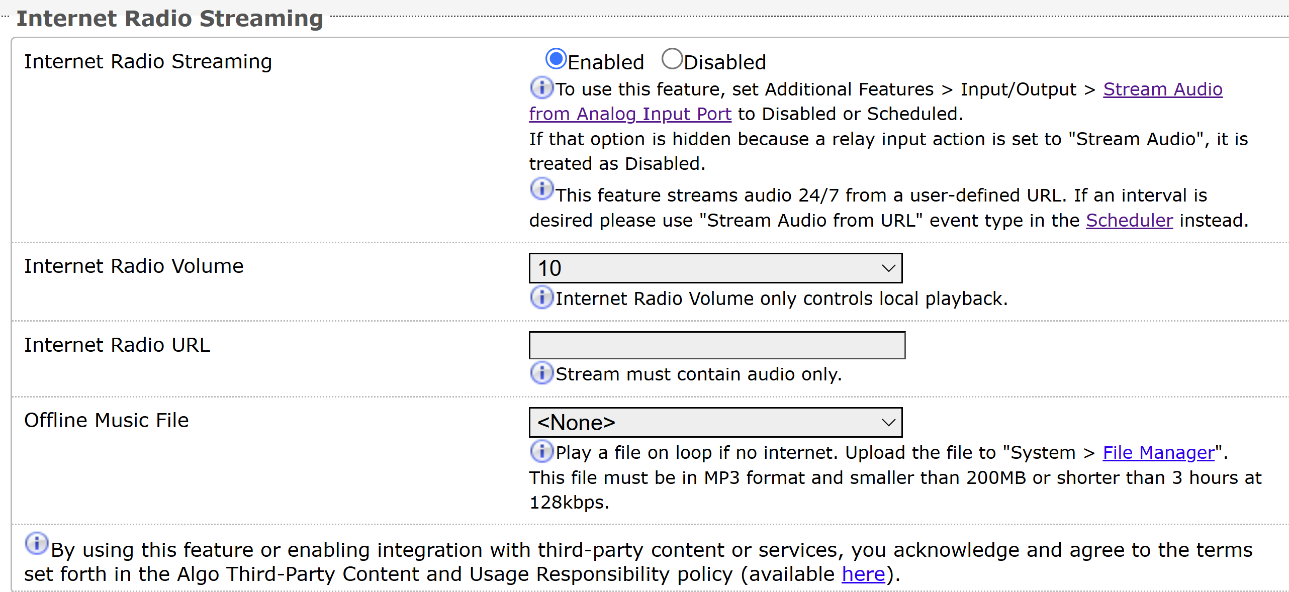
Note
When both the Offline Music File and Radio URL are specified, the Radio URL takes precedence if an Internet connection is available.
To configure Internet Radio Streaming:
Go to Advanced Settings → Advanced Audio.
Go to the Internet Radio Streaming section and configure the following:
Internet Radio Streaming: Set as Enabled.
Radio Volume: Set the audio output volume for the device’s AUX OUT port.
This volume doesn’t impact the multicast volume of the receiving devices.
Radio URL: Enter the stream URL.
Offline Music File: Select an audio file to stream.
Make sure you have uploaded at least one offline music file to the System → File Manager → Radio folder.
Multicast Zone: Select a zone to multicast the audio to.
Your device must be configured as a multicast transmitter first. The multicast output is RTP-only, using the L16 codec with a fixed packet size.
Select Save.
The Internet radio stream starts.
Stopping Internet Radio Streaming
You can disable Internet Radio Streaming to stop an ongoing stream.
This doesn’t change your Internet Radio Streaming settings.
To stop Internet Radio Streaming:
Go to Advanced Settings → Advanced Audio.
Go to the Internet Radio Streaming section and set Radio Streaming as Disabled.
Select Save.
Internet Radio Streaming FAQs
Why can’t I enable Internet Radio Streaming for my 8312?
Make sure Additional Features → Input/Output → Always Active is set to Disabled before using Internet Radio Streaming.
Why can’t I find my audio file in the Offline Music File drop-down list? It’s in the File Manager → radio folder.
The audio files must meet the following requirements to be available in the Offline Music File drop-down list for Internet Radio Streaming:
MP3 format
Smaller than 200 MB or shorter than 3 hours at 128 kbps
Scheduler
Your device includes calendaring functionality synchronized with Network Time Protocol (NTP). You can schedule events on the local device or other IP endpoints, including:
Play a pre-configured tone or alert to a multicast zone
Ideal for education or manufacturing environments where certain areas require regular bell schedules or announcements, while others do not.
Start a SIP call to trigger a pre-configured tone or alert on specific devices
Useful when triggering tones or announcements through the PBX for selected endpoints, such as targeted alerts, shift bells, or department-specific notifications.
Stream live audio to a multicast zone
Suitable for facility-wide announcements, background music, or emergency notifications that need to play simultaneously across all subscribed devices.
Schedule API calls from the device web interface to trigger actions on other devices
For example:
Activating a strobe light
Displaying a slide or slideshow on an IP display
Triggering an emergency alert
Triggering an InformaCast scenario
You can include up to 5 API calls in an API Call event.
For a complete list of API commands, see RESTful API Guide.
You can organize related events into a group so they can be scheduled and managed together.
You can create standalone and recurrent events, skip event or group instances in recurrent schedules, or restore skipped instances.
Note
If your device is configured as a Multicast Transmitter (Sender), the audio in the scheduled events (if available) will be multicast to receivers.
Scheduler Overview
The Scheduler interface is organized into several tabs that provide tools for managing scheduled announcements and events. The following table describes the purpose of each tab and the tasks that can be performed from it.
.png)
Item | Description |
|---|---|
1 | The Data tab allows you to:
|
2 | The Groups tab allows you to:
|
3 | The Events tab allows you to:
|
4 | The Calendar tab allows you to:
|
Using the Scheduler
You can create and manage schedules using one of the following methods:
Using the product's web interface: Refer to Using 8312 Scheduler.
Using the Remote Device UI from ADMP: Refer to the Algo Device Management Platform (ADMP) User Guide.
Using the RESTful API: Refer to the RESTful API Guide.
Creating a Dedicated Scheduler User Account
The Scheduler User Login feature creates a separate user account with limited access to the device web interface. This account allows users to manage the Scheduler without providing access to administrative settings.

When a Scheduler user logs in, only the Status and Scheduler menus are available. The user can create and modify scheduled events, calendars, groups, and scheduler data, but cannot view or change any device configuration settings.
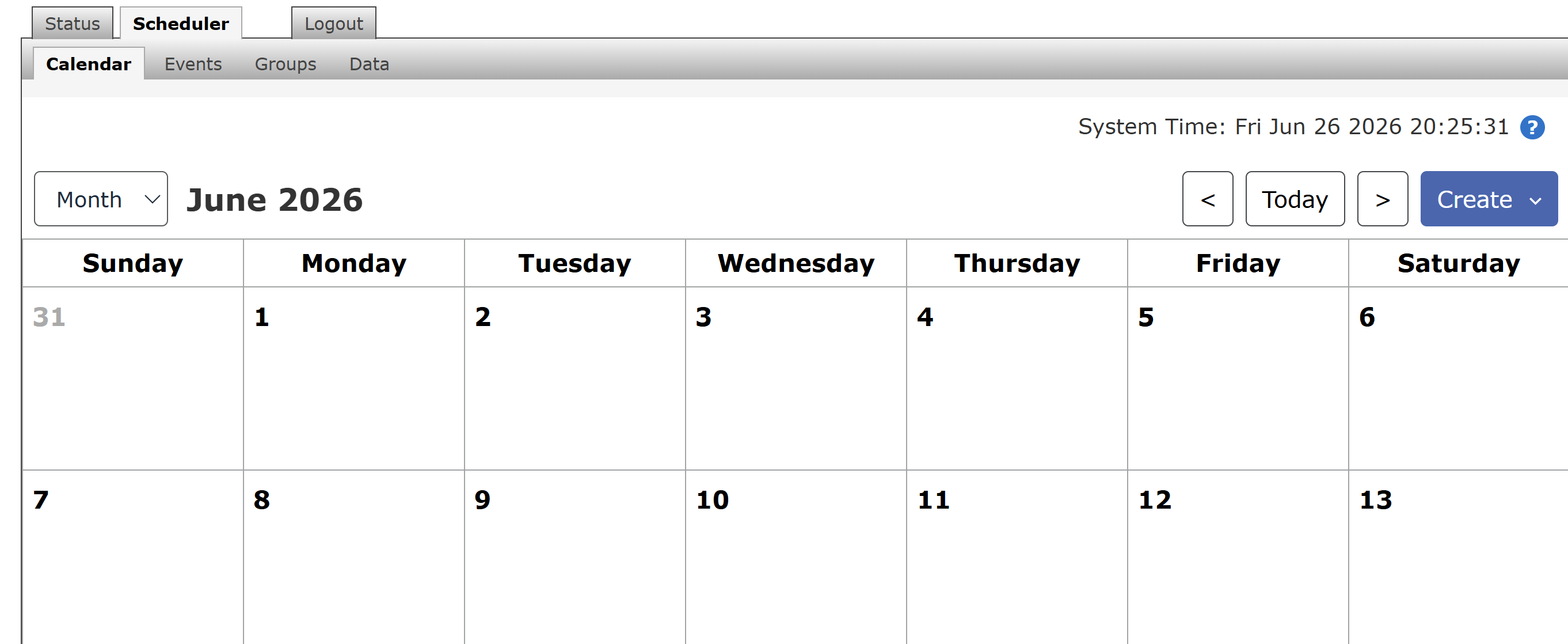 This feature is useful when non-administrative personnel, such as office staff, school administrators, or facility managers, need to maintain scheduled announcements or events without requiring full administrator access.
To configure a Scheduler user account:
Go to Advanced Settings → User Management.
Under Scheduler, select Enabled.
Enter a Username.
Enter a Password.
Click Save.
The Scheduler user account is now available from the login page.
To log in as the Scheduler user:
Open the device web interface.
From the User list, select the Scheduler user account.
Enter the Scheduler user's password.
Select Login.
The web interface displays only the Status and Scheduler menus. Administrative configuration pages are not available.
TLS for SIP Signaling and Provisioning
Algo devices support Transport Layer Security (TLS). This feature adds security by ensuring that Algo products can trust the hosted SIP server. This is useful for when third-party devices or attackers may try to intercept, replicate, or alter Algo products and try to connect to the server. The TLS protocol will ensure that third parties cannot read/modify any actual data. Previously, security was less of a concern because phone systems were on isolated networks, but hosted services are becoming increasingly more common. Using a hosted SIP service requires traffic to be sent over the public internet and is therefore much more susceptible to attacks. Signed certificates are important pieces in the operation of Algo devices to ensure the security, integrity, and privacy of device communication. Algo components that use TLS are Provisioning and SIP Signaling.
Algo devices come pre-loaded with certificates from a list of trusted certificate authorities (CA), which are installed in the hardware at the time of manufacture.
Note
These pre-installed trusted certificates are not visible to users and are separate from the certs folder.
The TLS handshake happens to make sure that the client and server can trust each other, and once that trust is established, the two parties can freely send encrypted data and decrypt any data that they receive. After the TLS handshake process is complete, a TLS session is established, and the server and client can then exchange messages that are symmetrically encrypted with a shared (pre-sender) secret key.
For further details, see Algo TLS guide for SIP Signalling and HTTPS Provisioning.
Uploading Public CA Certificates to Algo SIP Endpoints
If the particular CA Certificate is not installed by factory, you can easily upload your own.
To install the public CA certificate on the Algo 8312:
Obtain a public certificate from your Certificate Authority (Base64 encoded X.509 .pem, .cer, or .crt).
In the web interface of the Algo device, navigate to the System → File Manager tab.
Upload the certificate files into the certs/trusted directory.
Click the Upload button in the top left corner of the file manager and browse to the certificate.
Reach out to support@algosolutions.com to get the complete list of trusted certificate authorities loaded from factory.
For SIP TLS, if the Validate Server Certificate option is enabled in Advanced Settings → Advanced SIP tab, then the device will validate the SIP server against common certificate authorities.
For Provisioning, if HTTPS is selected and the Validate Server Certificate option is enabled in the Advanced Settings → Provisioning tab, then the device will validate the server against common certificate authorities.
To validate against additional certificates:
Go to System → File Manager.
Upload a Base64 encoded X.509 certificate file in .pem, .cer, or .crt format to the certs folder.
HTTPS Provisioning
Provisioning can be secured by setting the Download Method to HTTPS (under the Advanced Settings → Provisioning tab). This prevents configuration files from being read by an unwanted third-party. This resolves the potential risk of having sensitive data stolen, such as admin passwords and SIP credentials.
Note
To verify the server, enable the Validate Server Certificate option. This then checks if the certificate that is provided by the server is signed by any of the CAs included in the list of trusted CAs (used by the Debian infrastructure and Mozilla browsers). If we receive a certificate signed by any of these CAs, then that server will be trusted.
The ‘Validate Server Certificate’ parameter can also be enabled through provisioning:
Prov.download.cert = 1Using Configuration Files
When deploying the 8312, configuration files are used to provision the devices automatically. These configuration files define network settings, SIP credentials, and operational preferences, reducing the need for manual setup. There are two types of provisioning files available: generic and specific.
Generic configuration file: The configuration file is not tied to a specific device. It does not include the MAC address in its filename, and any Algo 8312 device connected to the network can automatically download and use this file from the provisioning server. However, you must enter SIP extensions and credentials manually.
Specific configuration file: The configuration file is intended for a single device and includes the device's MAC address in the filename. Only the Algo 8312 unit with the matching MAC address can download and use this file.
For more information, see the Algo’s SIP endpoint provisioning guide at www.algosolutions.com/provision.
MD5 Checksum
If using TFTP as a download mode, a .md5 checksum file must be uploaded to the provisioning server in addition to the .conf file. This checksum file is used to verify that the .conf file is transferred correctly without error.
To create an .md5 checksum file:
Download an MD5 tool. For example, http://www.fourmilab.ch/md5.
Extract the tool and open a command prompt in the same directory.
Run the
md5command with the target filename to generate the.md5file.To output the hash in lowercase, add the
-lparameter:Custom
md5 -l yourfilename.extPlain text
The resulting
.md5file will be saved in the same directory.
Securing SIP Signaling (and RTP Audio)
SIP signaling is secured by setting SIP Transportation to TLS (under the Advanced Settings → Advanced SIP tab). SIP transportation refers to the underlying protocol used for transmitting SIP messages between different entities in a network. Setting it to TLS ensures that the SIP traffic will be encrypted. SIP signaling is responsible for establishing the call (the control signals to start and end the call with the other party), but it does not contain the audio.
For the audio (voice) path, use the setting SDP SRTP Offer. Setting this to Optional means the SIP call’s RTP audio data will be encrypted (using SRTP) if the other party also supports audio encryption. If the other party does not support SRTP, then the call will still proceed, but with unencrypted audio. To make audio encryption mandatory for all calls, set SDP SRTP Offer to Standard. In this case, if the other party does not support audio encryption, then the call attempt will be rejected.
Integrations
The 8312 supports a wide range of third-party integrations, including radio systems, Microsoft Teams, InformaCast, and OAuth-enabled services.
These integrations allow the 8312 to extend paging, alerting, and notification workflows across public address systems, radio users, SIP platforms, cloud services, and third-party notification systems.
For a full list of compatible platforms and the configuration guides, see Compatible Platforms.
Motorola Curve Radio Integration
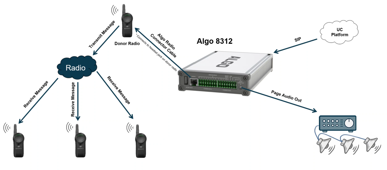
The 8312 can be used to distribute audio from UC platforms to overhead paging systems, compatible Motorola Curve radio users, or both simultaneously. This helps extend critical messages across public address systems, radio systems, and wider operational environments.
Note
Only audio from calls received on the main Ring Extension or Page Extension (configured under Basic Settings → SIP) can be routed to the RADIO output.
Configuring a Motorola Curve Donor Radio for Continuous Operation
The 8312 Expanded IP Paging Adapter requires a dedicated Motorola Curve donor radio that remains powered on continuously. By default, Motorola Curve radios enable the Auto Power Off (APO) feature, which automatically turns the radio off approximately 180 seconds after it is placed in a powered charger. This behavior prevents the 8312 from maintaining a permanent radio connection.
To use a Motorola Curve radio as a donor radio, disable the Auto Power Off feature using Motorola Customer Programming Software (CPS).
Note
A Motorola CPS Programming Cable (PMKN4154A) is required to configure the radio.
To disable Auto Power Off:
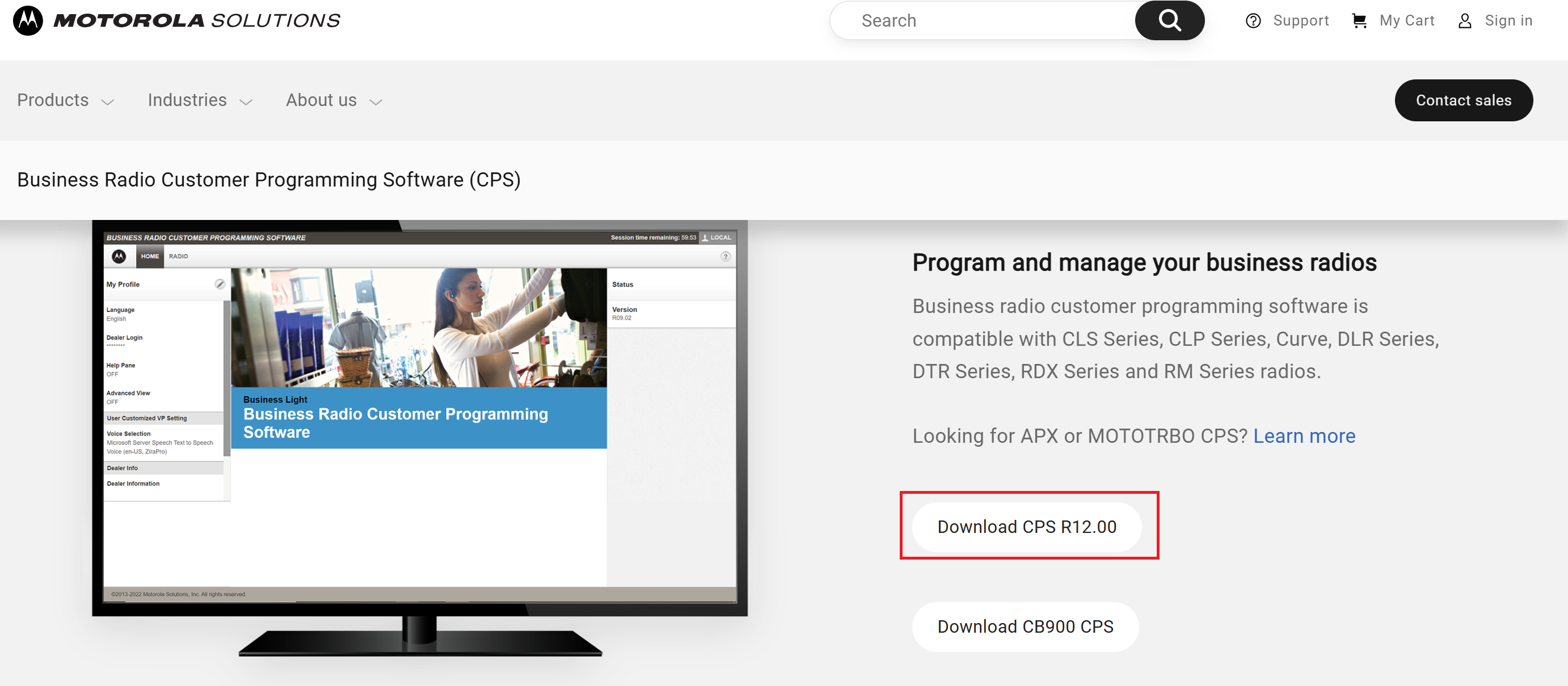
Download and install CPS R12 from Motorola Business Radio Customer Programming Software (CPS).
Verify that the switch in the Programming Cable is in Digital position.
Connect the Motorola charging cradle and your computer using the programming cable.
Place the Motorola Curve donor radio into the charging cradle.
Turn on the radio.
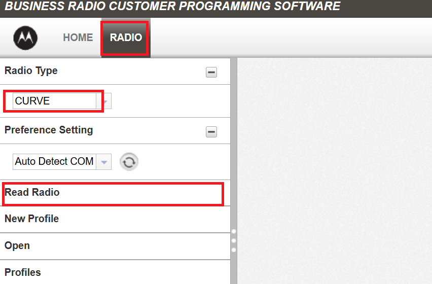
Open the Motorola CPS application.
Select the RADIO tab.
Select the Radio Type to CURVE.
Select Read Radio to read the current radio configuration. The radio uploads its configuration into CPS.
Locate the Auto Power Off (Sec.) and change the value to OFF.
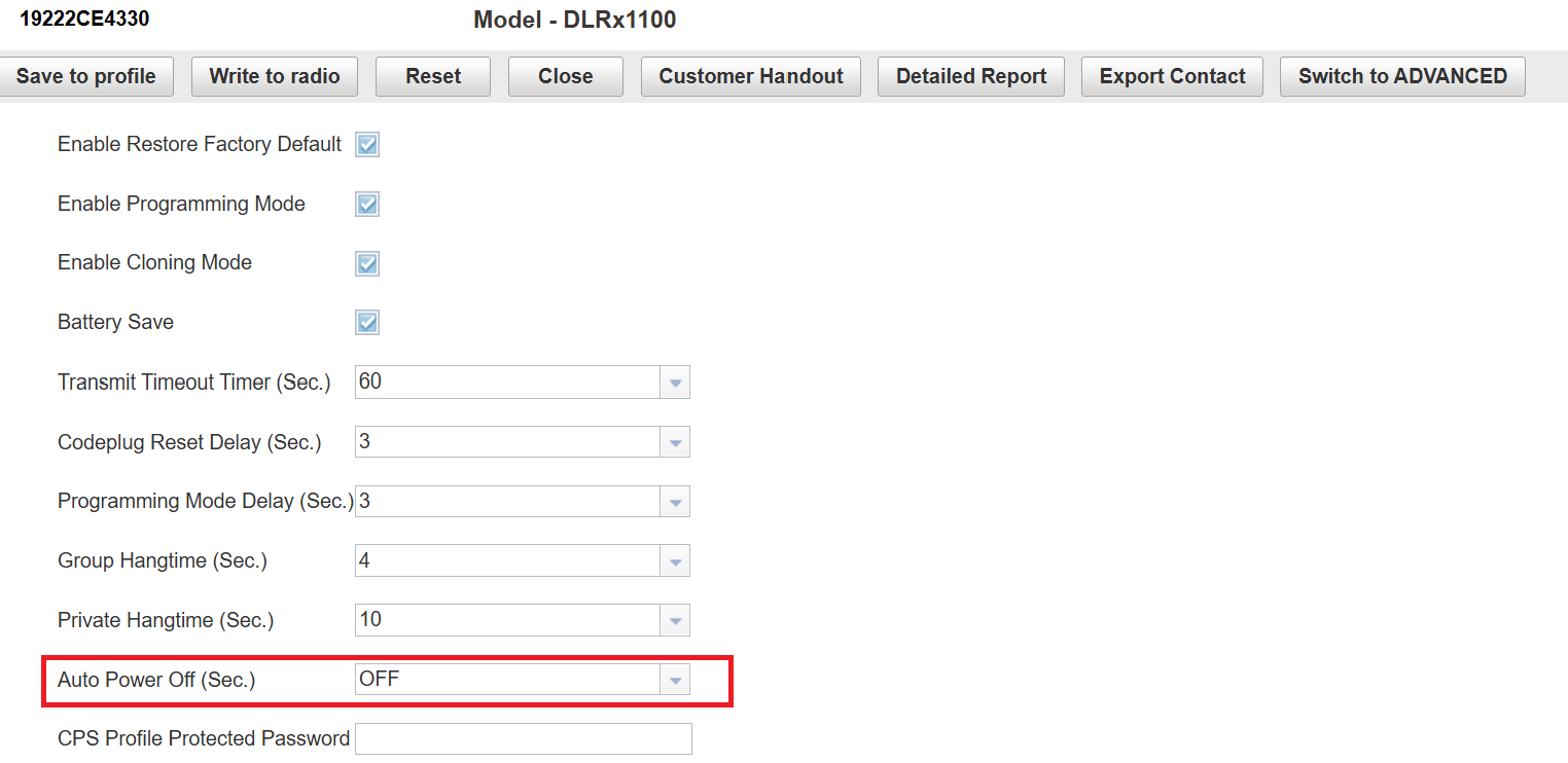
Select Write to radio to save the updated configuration to the radio.
After the programming completes, select Close.
The Motorola Curve donor radio no longer powers off automatically while it is in the charging cradle. It can remain continuously powered on, allowing the 8312 to maintain a permanent connection to the radio for Radio-to-PA and UC-to-Radio communication.
Integrating with a Motorola Curve System
The 8312 can integrate with a Motorola Curve system by connecting a Motorola Curve donor radio to the RADIO port. When configured, audio from calls received on the main Ring Extension or Page Extension can be transmitted to Motorola Curve radios. If the 8312 is also configured as a multicast transmitter, the same audio can be multicast to configured receiver zones.
Note
Only audio from calls received on the main Ring Extension or Page Extension (configured under Basic Settings → SIP) can be routed to the RADIO output.
To integrate the Motorola Curve System:
Connect a Motorola Curve donor radio to the RADIO port of the 8312 using a customized Radio Connector Cable.
You can purchase this cable from Algo (part number: 79-00062).
Go to Basic Settings → SIP and do the following:
Configure the SIP Domain (Proxy Server).
Configure the Ring Extension (also called main Ring Extension), or Page Extension (also called main Page Extension).
Set Audio Output to one of the following:
Radio Audio Output: Sends the audio to RADIO and AUX OUT interfaces.
Both: Sends the audio to PAGE AUDIO OUT, RADIO, and AUX OUT interfaces.
(Optional) To adjust audio output volume, go to Basic Settings → Feature → Audio and configure the desired settings.
Select Save.
When your 8312 receives calls on the main Ring Extension or main Page Extension, the audio in the call is transmitted to Motorola Curve radios.
Integration with Teams
Algo IP endpoints (including 8312) are certified for native compatibility with the Microsoft Teams SIP Gateway. Applications such as IP paging, emergency alerting, and hands-free visitor communication can be implemented using both Microsoft Teams and Algo IP endpoints.
You can configure Teams integration using one of the following ways:
Microsoft Teams Configuration with Algo IP Devices Using ADMP
Microsoft Teams Configuration with Algo IP Devices Using the Device Web Interface
Integration with InformaCast
Algo devices (including 8312) can do the following when integrated with InformaCast:
Receiving notifications from InformaCast
Triggering InformaCast Scenario
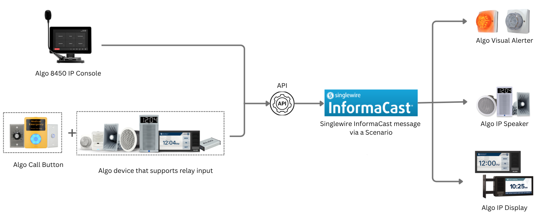
For more information, see Singlewire InformaCast Integration Guide.
Using OAuth for Authentication
OAuth (Open Authorization) is an industry-standard protocol that enables secure, delegated access to resources without requiring users to share credentials such as usernames and passwords.
Instead of storing static credentials on a device or application, OAuth allows a trusted third-party service (such as Google, Microsoft, or Slack) to issue time-limited access tokens. These tokens allow an Algo device to interact with the service on behalf of a user or system, without exposing sensitive login information.
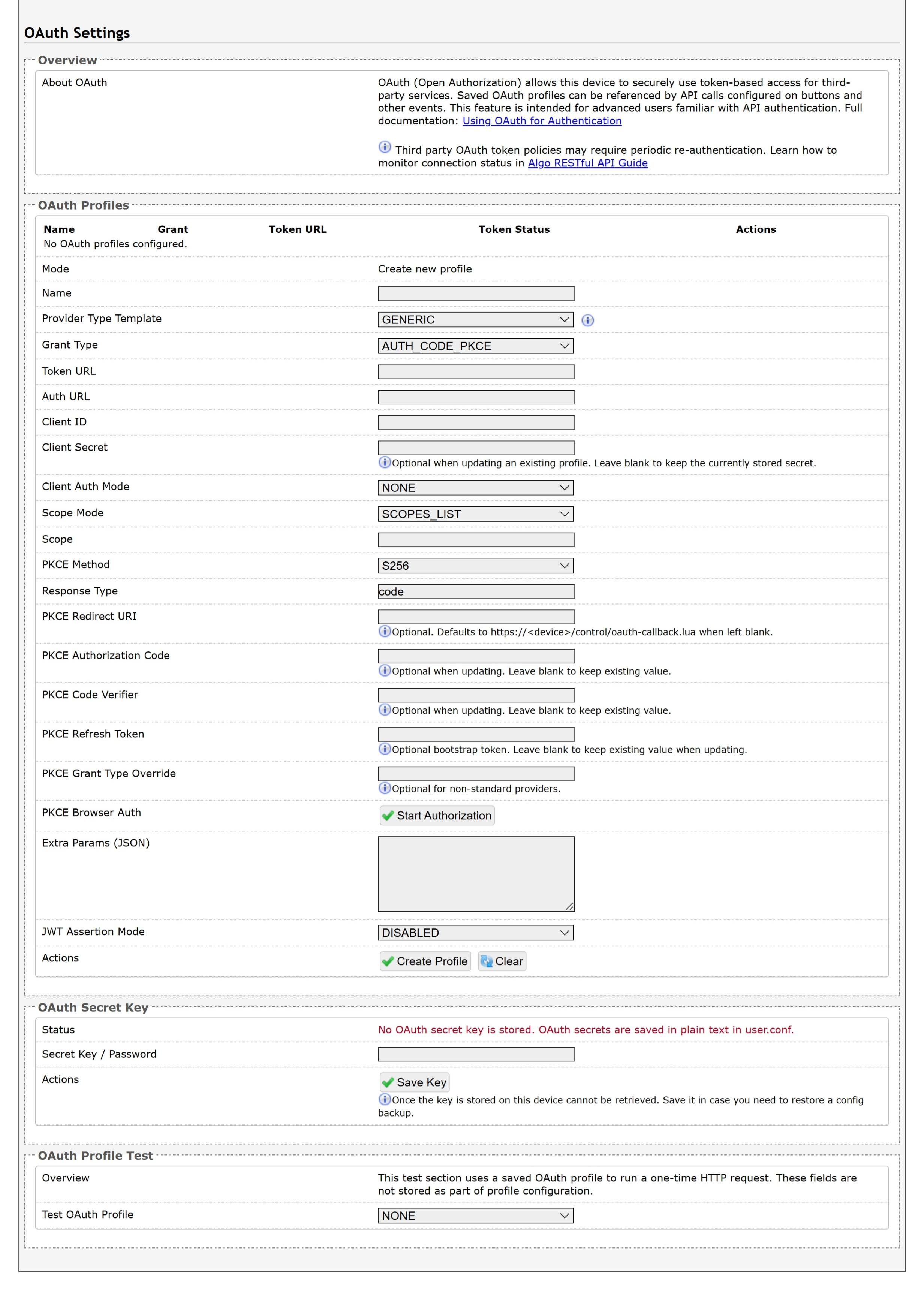
For more information, see Using OAuth for Authentication.
System Maintenance
You can back up the current configuration, restore previously saved settings, reset the device to its factory defaults, and perform maintenance tasks to support troubleshooting, recovery, and device redeployment.
Backing Up System Configuration
Saves the device settings (configuration) and all files stored in File Manager, including certificates, licenses, and tones, to a backup ZIP file. Back up the configuration before making major changes or upgrading the firmware so it can be restored if needed.
To download system configuration:
Go to System → Maintenance → Backup / Restore Configuration.
Select Download next to Download Configuration File.
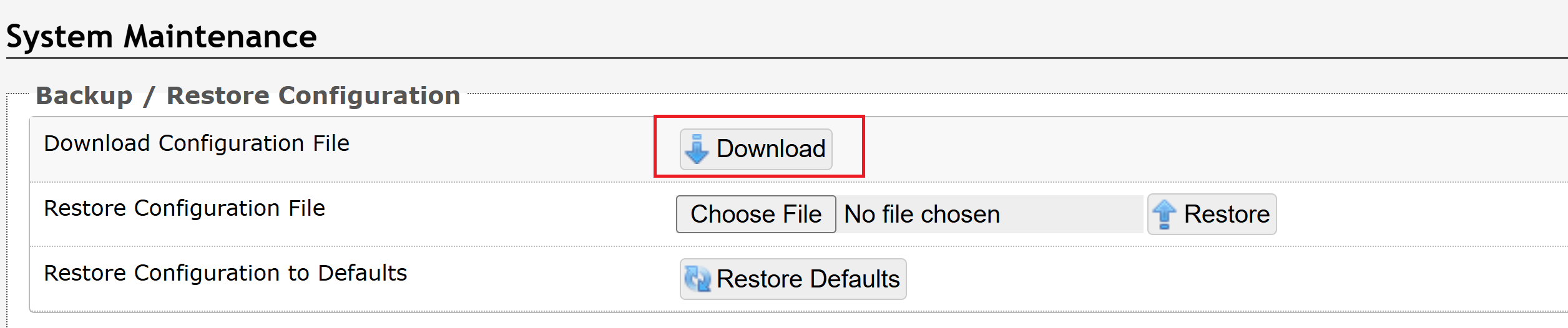
The configuration file is downloaded to your default downloads folder using the following file name format:
settings-<product_model>-<product_MAC_ADDRESS>.txt
Restoring the Device Configuration
You can restore the device configurations from a backup configuration file, or restore to its factory default settings using either the RESET button or the web interface.
You can also choose to restore the factory default settings and delete all preloaded and uploaded files.
Restoring Settings Using a Backup Configuration File
You can restore the device settings from a backup configuration file.
To restore settings using a backup configuration file:
Go to System → Maintenance → Backup / Restore Configuration.
Select Choose File next to the Restore Configuration File option.
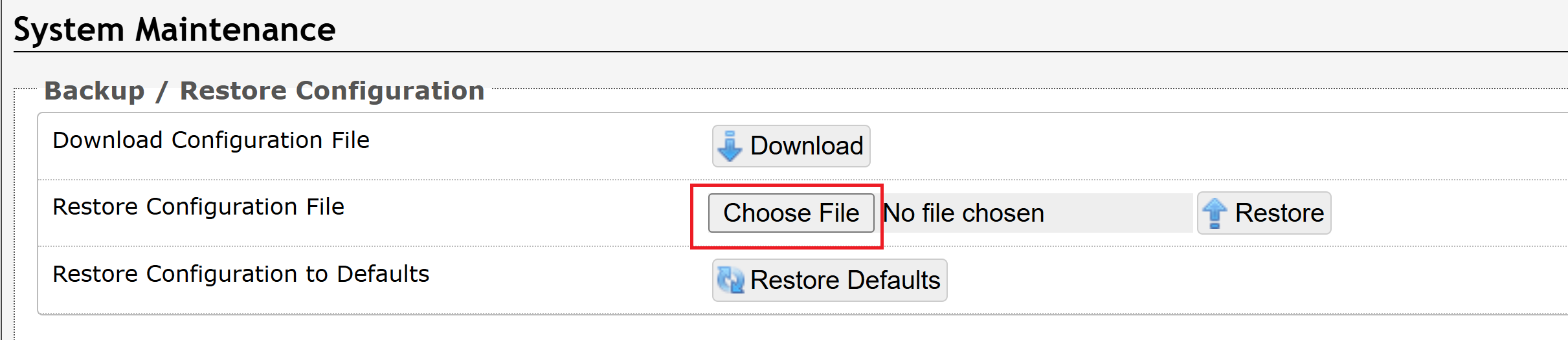
Select the configuration file, then select Restore.
The system reboots to restore the settings.
Restoring Factory Default Settings Only
Restore the factory default settings while keeping all preloaded and uploaded files. You can perform this operation using either the RESET button or the device's web interface.
To restore the factory default settings using the RESET button:
Reboot or power cycle the device.
Wait until the SIP LED begins flashing.
Press and hold the RESET button until the SIP LED begins a double-flash pattern.
Note
Do not press the reset button until the SIP LED begins flashing.
Release the RESET button.
Wait for the device to complete the boot process.
After the device has finished booting, press the Reset button once.
The device restores the factory default settings. When you press the RESET button after the boot process is complete, the device announces its IP address through the analog output ports.
To restore the factory default settings from your web interface:
Go to System → Maintenance → Backup / Restore Configuration.
Select Restore Defaults.

When asked to confirm this action, select OK.
The system reboots to restore the default settings.
Restoring Factory Default Settings and Deleting Files
You can restore the device to its factory settings and delete all preloaded and uploaded files.
This is useful when redeploying the device or performing a complete factory reset.
To reset the device factory default settings and delete files:
Go to System → Maintenance → Backup / Restore Configuration → Restore Defaults and Delete Files.

When asked to confirm this action, select OK.
The system reboots to restore the default settings. All preloaded and upload files are also deleted.
Managing Firmware
The Online Upgrade feature checks whether a newer firmware version is available from the Algo firmware server (firmware2.algosolutions.com). The device must have an active internet connection to perform this check.
Note
During the firmware update process, Algo devices communicate with two different hosts:
firmware2.algosolutions.com: Checks whether a newer firmware version is available.
algofw.sfo3.cdn.digitaloceanspaces.com: Downloads the firmware image when an update is available.
If your network uses outbound firewall rules, web filtering, or proxy allowlists, ensure that HTTPS (TCP port 443) access to both hosts is permitted. Blocking either host may prevent firmware updates from completing successfully.
To check for firmware updates:
Go to System → Firmware.
Under Online Upgrade, click Check.
Wait while the device checks for the latest firmware.
If the device is running the latest firmware, Latest Firmware displays Firmware up to date.
If a newer firmware version is available, the available firmware version is displayed.
Upgrading or Downgrading Firmware
The Custom Upgrade section allows you to manually install firmware when internet access is unavailable or when instructed by Algo Technical Support.
You can install firmware from a signed firmware file stored on your computer or from a firmware download URL.
To install firmware from a local file:
Download the signed firmware file from the Algo firmware downloads page.
Go to System → Firmware.
Under Method, select From Local Files.
Click Choose File.
Browse to and select the signed firmware file.
Select Upgrade.
After the device restarts, verify that the firmware version has been updated.
To install firmware from a URL:
Copy the firmware download URL from the Algo firmware downloads page.
Go to Firmware.
Under Method, select From URL.
Enter the firmware download URL in Upgrade URL.
Start the firmware upgrade.
After the device restarts, verify that the firmware version has been updated.
Allowing Firmware Downgrade
The Allow Downgrade option controls whether the device can install an earlier firmware version.
Note
Downgrading firmware may affect future firmware upgrades. If you need to downgrade the firmware, contact Algo Technical Support for assistance.
To allow firmware downgrades:
Enable Allow Downgrade only if instructed by Algo Technical Support.
Managing System Log
The System Log provides a record of device events and operational messages that can help monitor system activity and troubleshoot issues. You can view the log to verify device operation, identify errors or warnings, and gather diagnostic information when investigating configuration or network problems.
Configuring Log Settings
The Log Settings page allows you to configure how the device records and manages system log messages. You can adjust the logging level, enable or disable remote logging, and specify a remote syslog server to collect log information for centralized monitoring, diagnostics, and troubleshooting.
To configure the log settings:
Go to Advanced Settings → Admin → Log Settings.
Configure the following:
Log Level: Select the appropriate level for the information you want to capture.
Note
Change the Log Level only under the guidance of Algo Technical Support. Higher log levels generate additional diagnostic information, which may clutter the logs and make routine monitoring and troubleshooting more difficult.
Log Method:
Local: The log file is saved in RAM on the device.
Network: Send the log file to an external SysLog server so settings are not lost if the device is rebooted, or for ease of central access.
Both: Use both methods.
Note
The default port when using UDP/TCP is 514. The default port when using TLS is 6514. To specify a different port, enter ADDRESS:PORT. When using TLS, use the System → File Manager tab to upload the CA certificate renamed to ca.pem to the certs/syslog folder. If the server is using peer certificate authentication, also upload the certificate/key pair renamed to cert.pem and key.pem.
Log Server: Enter the Syslog server address provided by your IT Administrator.
Log Additional Events: To be used by support@algosolutions.com if necessary.
Select Additional Log Events: To be used by support@algosolutions.com if necessary.
Note
Configure additional log events only when requested by Algo Technical Support. These options are intended for advanced troubleshooting.
Select Save.
Downloading System Logs
The System Log contains diagnostic information that can help identify and troubleshoot device issues.
To retrieve system logs:
Go to System → System Log.
Do one of the following:
Download: Save the log file to your local disk.
View: View the log information on-screen.
Provide the file to Algo Technical Support if requested.
Managing Files Using File Manager
Use File Manager to manage the files stored on the device. You can upload, download, replace, and delete supported files, including audio files, certificates, and license files.
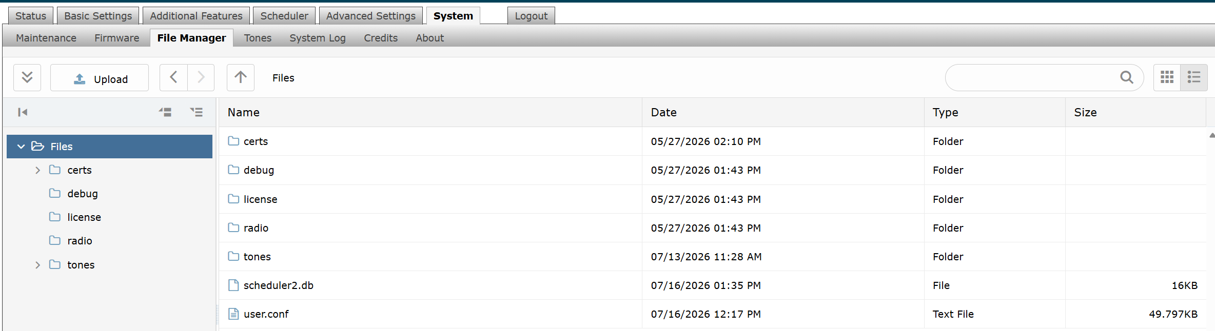
File Formats
The File Formats section lists the supported file types and requirements for files that can be uploaded to the device.
Folder | Supported format | Requirements |
|---|---|---|
License | LIC | None |
Tones | 8SVX, AIF, AIFC, AIFF, AIFFC, AL, AMB, AMR-NB, AMR-WB, ANB, AU, AVR, AWB, CAF, CDDA, CDR, CVS, CVSD, CVU, DAT, DVMS, F32, F4, F64, F8, FAP, FLAC, FSSD, GSM, GSRT, HCOM, HTK, IMA, IRCAM, LA, LPC, LPC10, LU, MAT, MAT4, MAT5, MAUD, MP2, MP3, NIST, OGG, PAF, PRC, PVF, RAW, S1, S16, S2, S24, S3, S32, S4, S8, SB, SD2, SDS, SF, SL, SLN, SMP, SND, SNDFILE, SNDR, SNDT, SOU, SOX, SPH, SW, TXW, U1, U16, U2, U24, U3, U32, U4, U8, UB, UL, UW, VMS, VOC, VORBIS, VOX, W64, WAV, WAVPCM, WV, WVE, XA, XI | Audio files must be in the following format:
|
Radio | MP3 | Audio files must be smaller than 200 MB or shorter than 3 hours at 128 kbps. |
Certs Folder
The certs folder stores trusted Certificate Authority (CA) certificates used when validating server certificates.
Upload additional certificates only if Validate Server Certificate is enabled under Advanced Settings → Advanced SIP.
To install a public CA certificate:
Obtain a Base64-encoded X.509 certificate (.pem, .cer, or .crt) from your Certificate Authority.
Go to System → File Manager.
Open the certs folder.
Click Upload.
Select the certificate file.
The certificate is added to the trusted certificate store.
For a list of pre-installed trusted certificates, contact support@algosolutions.com.
Debug Folder
The debug folder stores diagnostic files generated by the device.
Diagnostic files are used by Algo Technical Support to troubleshoot device issues.
To retrieve diagnostic files:
Go to System → File Manager.
Open the debug folder.
Download the requested diagnostic files.
Provide the files to Algo Technical Support.
License Folder
The license folder stores license files required to enable licensed features.
To install a license:
Obtain the license file from Algo.
Go to System → File Manager.
Open the license folder.
Click Upload.
Select the license (.lic) file.
The license is installed and becomes available after the upload completes.
Tones Folder
The tones folder stores custom audio files used for paging and notification applications.
To upload a custom audio file:
Go to System → File Manager.
Open the tones folder.
Click Upload.
Select the audio file from your computer.
Wait for the upload to complete.
The uploaded audio file is available for notification applications.
To replace an existing audio file:
Download the existing audio file.
Modify the file as required.
Save the modified file using a different file name.
Upload the new file to the tones folder.
Note
Audio files must meet the supported format and file requirements listed in File Formats.
Radio Folder
The radio folder stores custom audio files used for offline Internet Radio Streaming.
To upload a custom audio file:
Go to System → File Manager.
Open the radio folder.
Click Upload.
Select the music file from your computer.
Make sure the file be in MP3 format, smaller than 200 MB or shorter than 3 hours at 128 kbps.
Wait for the upload to complete.
The uploaded audio file is available in the Offline Music File drop-down list under Advanced Settings → Advanced Audio → Internet Radio Streaming.
Managing Tones
Tone files are used for ringing, alerts, and other audio notifications on the device. You can download the default Algo tone files, rebuild tone cache files if tones do not play correctly, and test tone files directly from the device interface.
Downloading Tone Files
Your device includes a set of default ring tones, stored in System → File Manager → Tones. If you delete any of these files, you can download them again to restore the original ring tones.
To download Algo default tone files:
Go to System → Tones.
Do one of the following:
To download the tone files and install them into your File Manager → Tones folder, select Download and Install.

To download them to your local disk, select the Algo website link.

Rebuilding Tone Cache Files
Rebuild Tone Cache Files recreates the cached versions of all tone files on the device. Use this option only if the tone cache is out of sync with the tone files, such as when uploaded or modified tones do not play correctly. The operation does not change or delete the original tone files and may take several minutes depending on the number and size of the files.
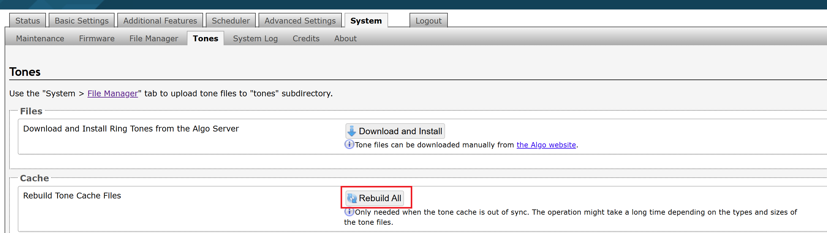
To rebuild tone cache files:
Go to System → Tones → Cache.
Select Rebuild All.
Testing Tone Files
You can play uploaded audio files directly through the device to verify that they sound as expected.
To test tone files:
Go to System → Tones.
In the Cache section, select Test Tones.
In the Test Tones section, select an audio file and select Play or Loop.
To stop the playback, select Stop.
Appendix: Web Interface Reference
This section provides an overview of the pages and settings available in the 8312 web interface. It describes the purpose of each configuration page to help you locate and configure the settings required for your deployment.
SIP Settings
The SIP tab under Basic Settings allows for the SIP server information and account credentials to be entered. This information can be obtained from your telephone system administrator or hosted account provider. After entering the information and saving the settings, go to the Status tab to confirm the registration was successful.
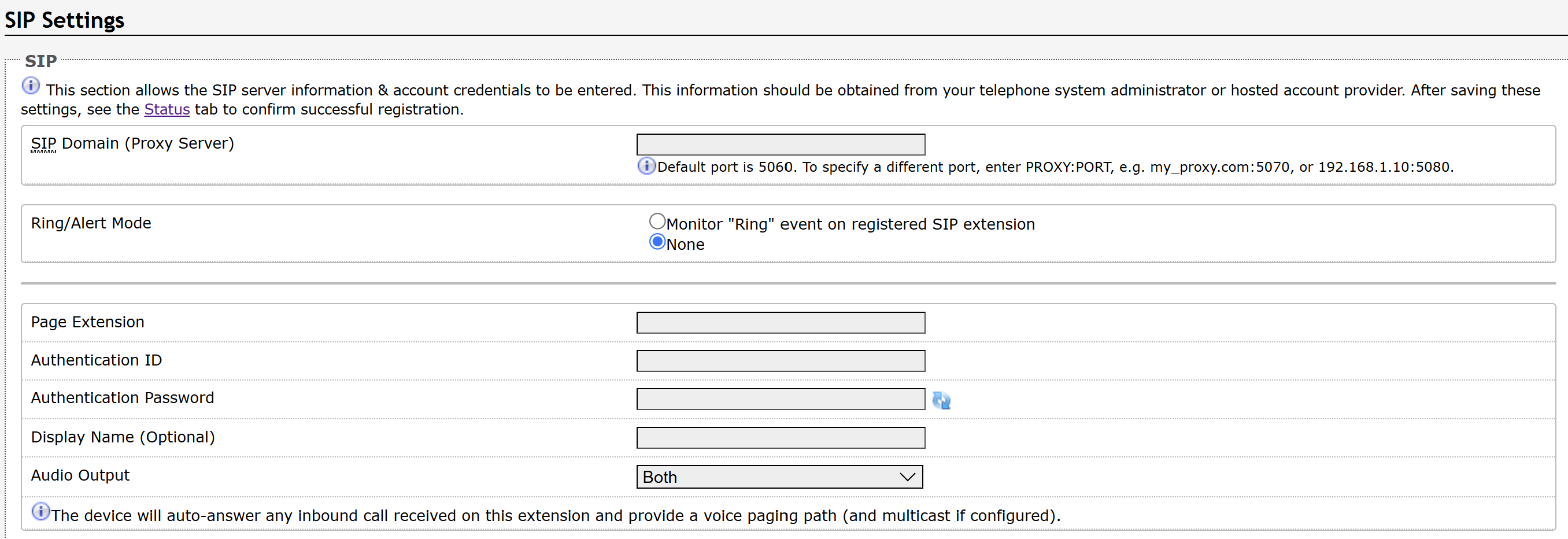
SIP | |
SIP Domain (Proxy Server) | The SIP Server's IP address (e.g., 192.168.1.111) or domain name (e.g., myserver.com). |
Ring/Alert Mode | Ring extensions do not answer incoming calls but play a customizable, pre-recorded announcement, such as a loud ringer (night bell). Announcements are customizable and can be pre-recorded. Use this setting to add a second SIP extension for a Ring event.
When enabled, the device will detect inbound ring events on this extension and play the alerting tone (and multicast if configured) until the inbound call stops ringing. The 8312 will not answer the call on this extension. Often, the 8312 will be a member of a hunt group or ring group to ring in conjunction with a telephone. You may change the alert tone from Basic Settings → Features. |
Ring Extension | Enter the SIP extension for the ring parameter of the 8312. |
Page Extension | Enter the SIP page extension for the 8312 so the device will auto-answer any inbound call received on this extension and provide a voice paging path (and multicast if configured). |
Authentication ID | The Authentication ID is associated with the page extension. It is also referred to as ‘Username’ for some SIP servers. This may be the same as the Ring or Page extension in some cases. |
Authentication Password | This is the SIP password for the registered SIP account used to authenticate SIP users. |
Display Name (Optional) | Enter the name you want to display on the receiving device when you place a SIP call. For the display name to be shown, the PBX and phone(s) must be configured to display this message as the Caller ID. |
Audio Output | Configure where the audio is output to:
|
Features Settings
Features configure the device's operational functions and optional capabilities, such as audio behavior, paging, alerts, multicast, and other feature-specific settings.
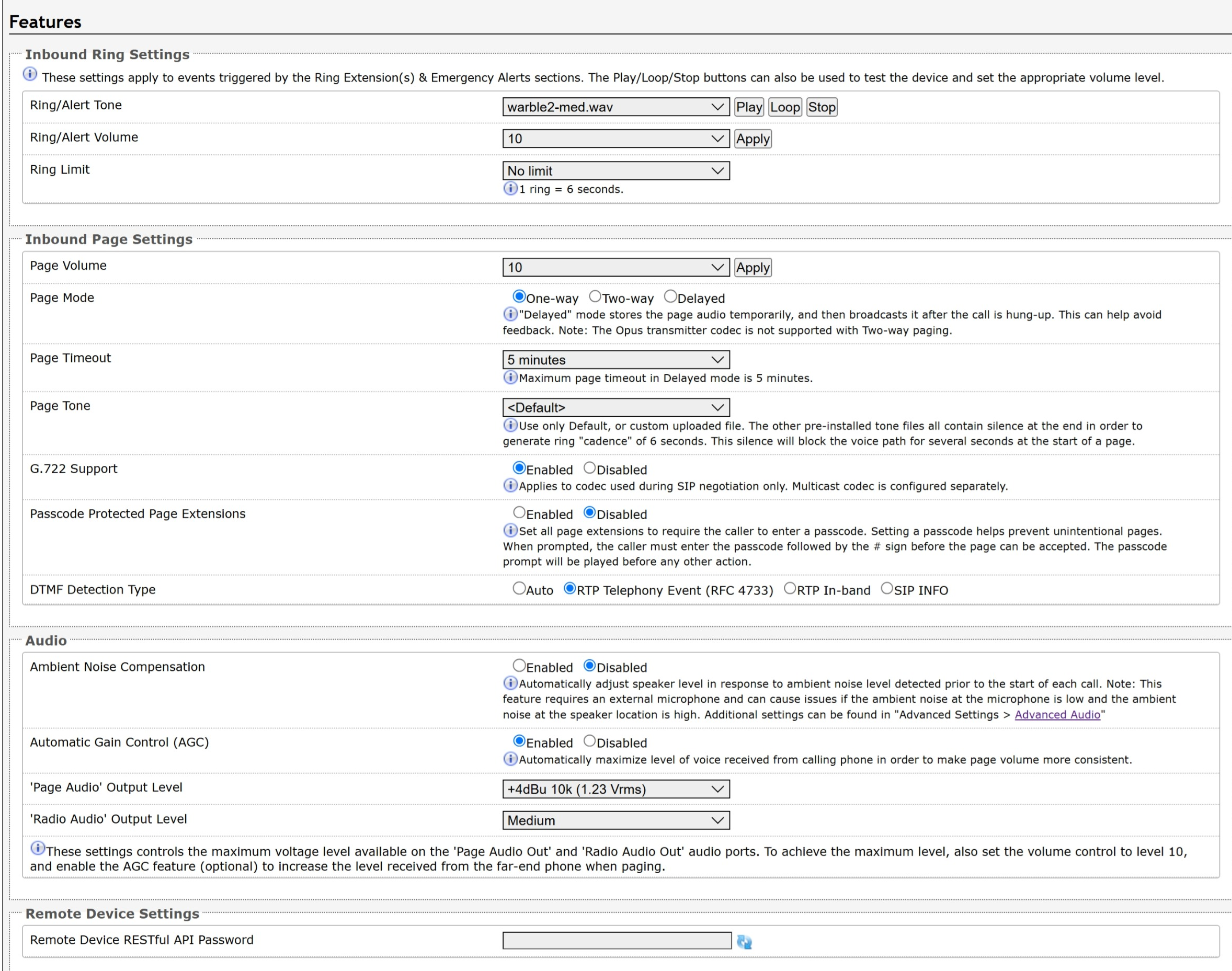
Inbound Ring Settings Ring settings apply to events triggered by Ring Extensions and Emergency Alerts. Emergency Alert tones are configured under Additional Features → Emergency Alerts. | |
Ring/Alert Tone | Select an audio file to play when a ring event is detected on the SIP Ring Extension. Test the audio file using the Play, Loop, and Stop buttons. During multicast, the device will broadcast an audio stream using the Transmitter’s selected ringtone. This is the default tone that will be played if selected in the settings Multicast → Additional Ring Extension. |
Ring/Alert Volume |
See Page Volume below for the volume settings used for all audio received over multicast. |
Ring Limit | Typically set to No Limit. Ring Limit will limit how long the speaker will ring before timing out. After the ring limit, a new ring event must occur for the speaker to play the audio file again. |
Inbound Page Settings | |
Page Volume |
|
Page Mode |
In Delayed Mode, the speaker will record a message to be played after hanging up. The device will buffer an announcement up to 5 minutes long. To cancel a page while in delayed mode, press |
Page Timeout | Set the maximum duration for a page. The page will end when the timeout limit has been reached. This is useful to ensure the paging system is not stuck in an active state in cases where someone accidentally forgets to hang up or puts the call on hold by mistake. |
Page Tone | Select a pre-page tone to be played when a page starts. Use only the Default or custom uploaded files. Other pre-installed tone files contain silence at the end to generate a ring "cadence" of 6 seconds. This silence will block the voice path for several seconds at the start of a page. The “Default” tone is set to page-notif.wav. The Default Page Tone in Advanced Multicast will play the tone set here. |
G.722 Support | Enable or disable the G.722 codec. G.722 enables wideband audio for optimum speech intelligibility. |
Passcode Protected Page Extensions | When enabled, the caller must enter the set passcode followed by the # sign before the page can be made. Setting a passcode helps prevent unintentional pages. |
Apply to All Page Extensions | Only visible when Passcode Protected Page Extensions is set to Enabled. Enable or disable a passcode for all page extensions. |
Passcode | Only visible when Passcode Protected Page Extensions is set to Enabled. Passcodes can be up to 15 digits and must be numbers only. |
Passcode Prompt Tone | Only visible when Passcode Protected Page Extensions is set to Enabled. Select the tone to be played to prompt the user to enter the passcode before paging. |
DTMF Detection Type | Select the preferred dual-tone multi-frequency (DTMF) detection method.
|
Audio Processing | |
Ambient Noise Compensation | When enabled, Ambient Noise Compensation will allow the speaker level to adjust automatically in response to ambient noise levels detected at the device before the start of each call. The volume is adjusted automatically via the speaker's microphone. |
Automatic Gain Control (AGC) | Enable AGC to normalize the audio level. Enabling this feature ensures the speaker is always played at a consistent volume. |
'Page Audio' Output Level | The following output levels are available, allowing the 8312 to interface with a wide variety of amplifiers:
|
'Radio Audio' Output Level | The following output levels are available, allowing the 8312 to interface with a wide variety of amplifiers:
|
Remote Device Settings | |
Remote Device RESTful API Password | When your device sends an API request to a device that requires authentication, enter the API password here. The password must match the RESTful API password configured on the target device. |
Multicast: Transmitter (Sender) Settings
When you set the Multicast Mode to Transmitter (Sender), you can configure your device to transmit multicast audio to compatible Algo IP endpoints, multicast-enabled IP phones, and supported Poly devices. You can configure multicast modes, zones, Poly group paging settings, and DTMF-based zone selection to control how and where paging audio is distributed across the network.
For more information, see Configuring Your Device as a Multicast Transmitter.
Note
Always ensure that the multicast settings (such as zone numbers, the multicast IP address, and port definitions) on all receiver devices match those of the transmitter device.
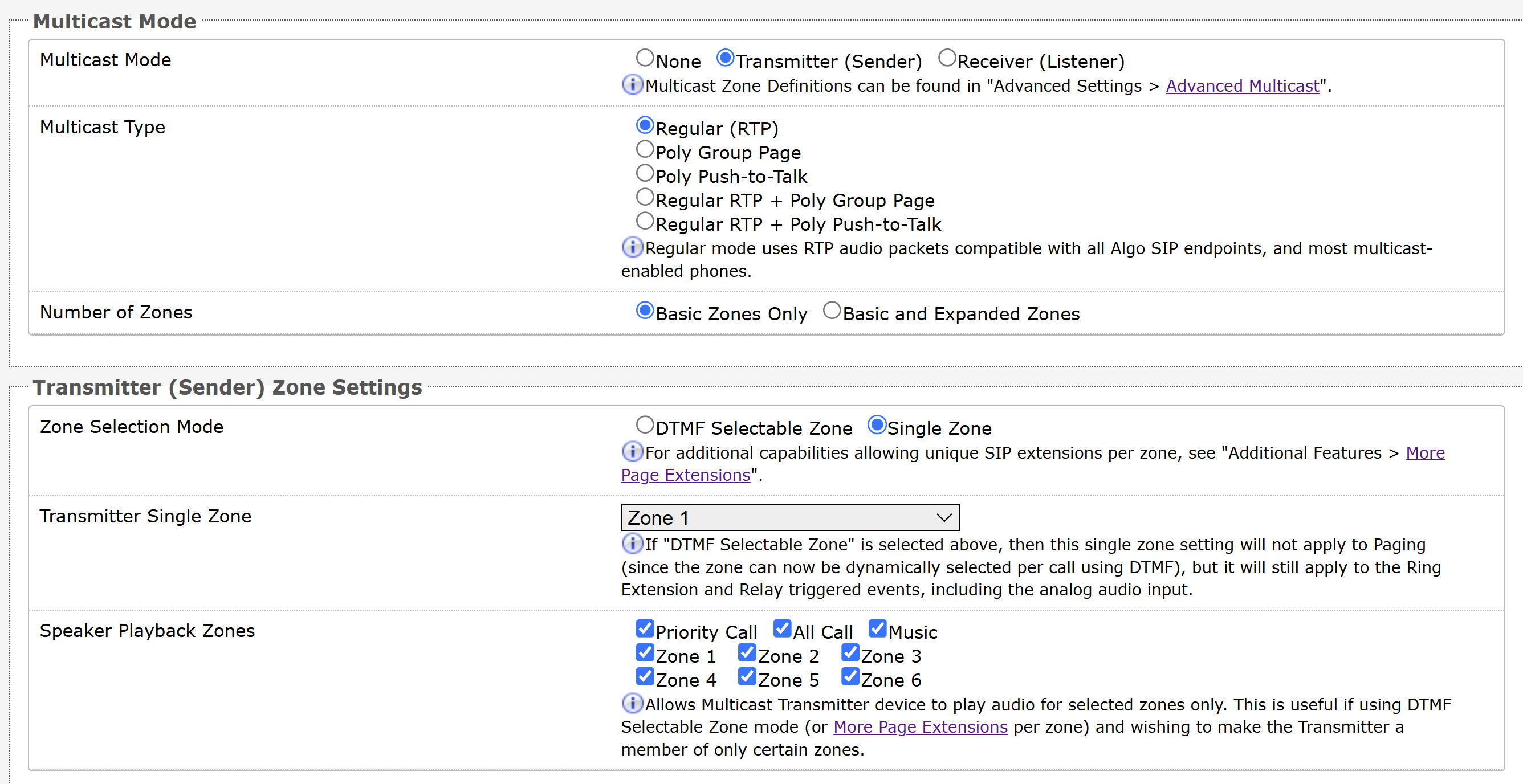
Multicast Mode | |
Multicast Mode | If Transmitter (Sender) is selected, the 8312 will broadcast an IP stream when activated in addition to playing audio. The 8312 cannot be both a multicast transmitter and receiver simultaneously.
|
Multicast Type | The 8312 may broadcast multicast paging compatible with Poly “on-premise group paging” protocol and most multicast-enabled phones that use RTP audio packets.
|
Number of Zones |
|
Poly Group Paging/Push-to-Talk This section is used if the Multicast Type includes Poly Group Page or Poly Push-to-Talk. | |
Poly Zone | Enter the same Multicast IP Address and Port number configured on the Poly phones. |
Poly Group Selection Mode |
|
Poly Default Channel | Select the default group for the multicast stream to be sent to. If DTMF Selectable Group is chosen, this setting will not apply to paging since the group will be dynamically selected per call using DTMF. The Single Group setting will still apply to the ring extension and relay triggered events. The Poly Default Channel is the default channel used for multicast actions unless an option is available for a custom channel with specific parameters. |
Speaker Playback Groups | Select Speaker Playback Groups to control which specific groups can play audio from the device. This is useful if using the DTMF Selectable Group mode or additional page extensions (Additional Features → More Page Extensions) per group to make 8312 a member of only certain zones. In this case, the Transmitter does not participate in the Zone but transmits certain traffic. |
Transmitter (Sender) Zone Settings This section is used if the Multicast Type includes Regular (RTP). | |
Zone Selection Mode |
|
Transmitter Single Zone | Select the default zone for the multicast stream to be sent to. The Transmitter Single Zone is the default zone used for multicast actions unless an option is available for a custom zone with specific parameters. If DTMF Selectable Zone is chosen, this setting will not apply to paging because the zone will be dynamically selected per call using DTMF. However, this setting will still apply to the ring extension and relay-triggered events. |
Speaker Playback Zones | Select Speaker Playback Zones to control which specific zones the 8312 can play audio for. This is useful if using the DTMF Selectable Zone mode or additional page extensions (Additional Features → More Page Extensions) per zone to make the 8312 a member of only certain zones. In this case, the transmitter does not participate in the zone but can still send audio to speakers in different zones. |
DTMF Settings This section is used if the Zone Selection Mode is set to DTMF Selectable Zone. | |
Zone Selection Tone | Select a tone to be played to prompt a user to select a zone to multicast to. This may be used as an interactive voice response (IVR) menu by uploading a custom audio file in the tones folder through System → File Manager. Each zone may use a different tone. This can be configured in Advanced Settings → Advanced Multicast. |
Two-Digit Selection | When enabled, all DTMF Selectable Zones will require two digits. As a result, Basic Zones must be prefixed with 0, and Expanded Zones will no longer need to be prefixed with *. |
Multicast: Receiver (Listener) Settings
When you set the Multicast Mode to Receiver(Listener), you can configure the device to receive multicast audio from compatible Algo IP endpoints, multicast-enabled IP phones, and supported Poly devices. You can configure the multicast mode, receiver zones, and Poly group paging settings to control which multicast streams the device monitors and plays.
For more information, see Configuring Your Device as a Multicast Receiver.
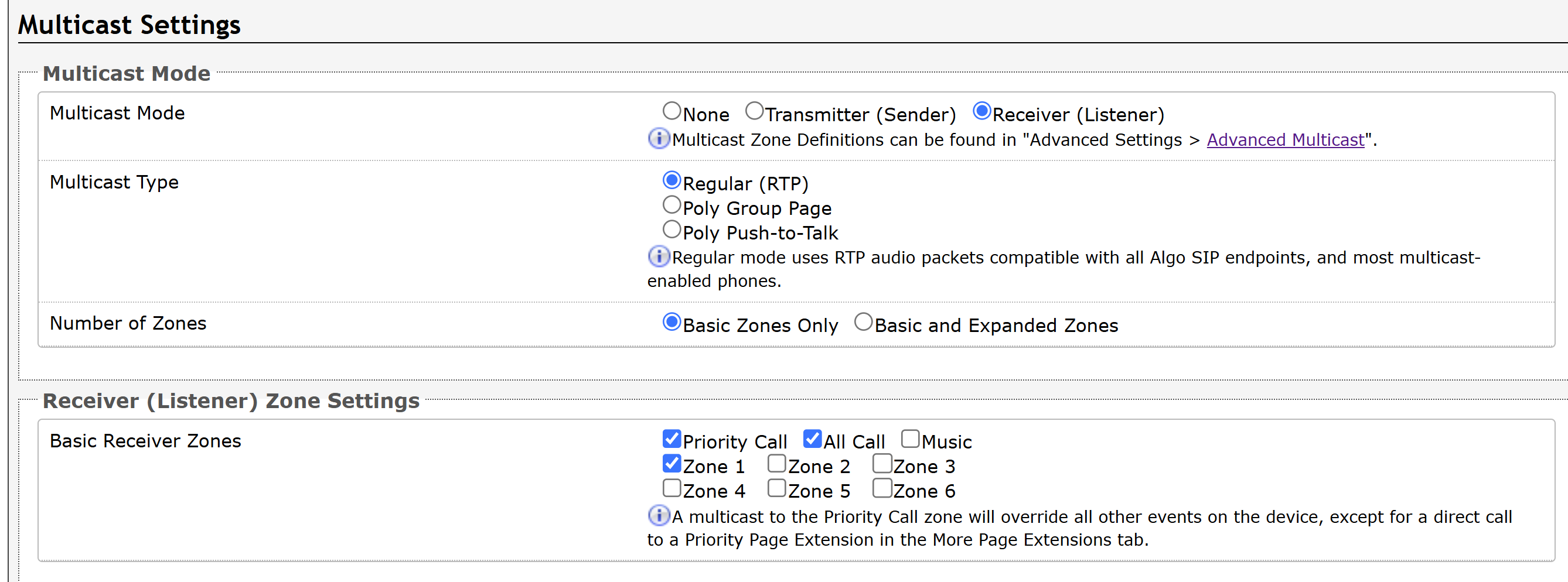
Multicast Mode Always ensure that the multicast settings on all Receiver devices match those of the Transmitter. | |
Multicast Mode | If Receiver (Listener) mode is selected, the 8312 will activate when receiving a multicast audio stream. It will mimic the audio stream of the transmitter but use local volume settings. This can be set via Basic Settings → Features → Page Volume. |
Multicast Type | Regular: Receive multicast from other Algo IP endpoint(s) and/or multicast-enabled phone(s) that use RTP audio packets. Poly Group Page or Poly Push-to-Talk: Receive multicast paging compatible with Poly “on-premise group paging” protocol. |
Number of Zones | Basic Zones Only: Configure nine or fewer multicast zones. Basic and Expanded Zones: Configure up to 50 zones. The expanded zones have the same behavior as the basic Receiver zones, but are hidden by default to simplify the interface. |
Receiver (Listener) Zone Settings | |
Basic Receiver Zones | Select one or more multicast zones for the 8312 to listen to. Multicast zone priority will be based on the zone definition list order defined in Advanced Settings → Advanced Multicast. |
Expanded Receiver Zones | Select additional zones (up to 50) for the device to listen to. This is only possible when Basic and Expanded Zones is selected. |
Poly Group Paging/Push-to-Talk
| |
Poly Zone | Enter the Poly Zone (IP Address and Port) that matches the configuration of the Poly phones and Channels. |
Poly Receiver Channels | If using a Poly telephone as a Multicast Transmitter, a tone may be set for any of the 25 Poly Groups configured on the 8312. Poly Group Tones can be set in Advanced Settings → Advanced Multicast. The Poly telephone used as a page audio source for the 8312 must be configured to use either the G.711 or G.722 audio codec. Note that Poly phone(s) must be configured with the “Compatibility” setting (“ptt.compatibilityMode”) disabled for this codec setting to be applied. |
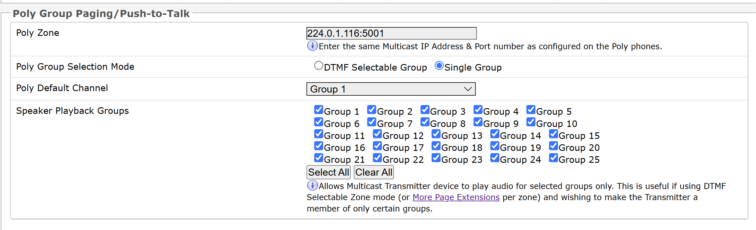
Input/Output Settings
The Input tab allows external accessories to be connected to the 8312. This is a dry contact input which can be configured as normally open or normally closed mode. Algo offers accessories, such as the 1202, 1203, 1204, and 2507. Third-party accessories/systems may also be used provided they have a dry contact output.
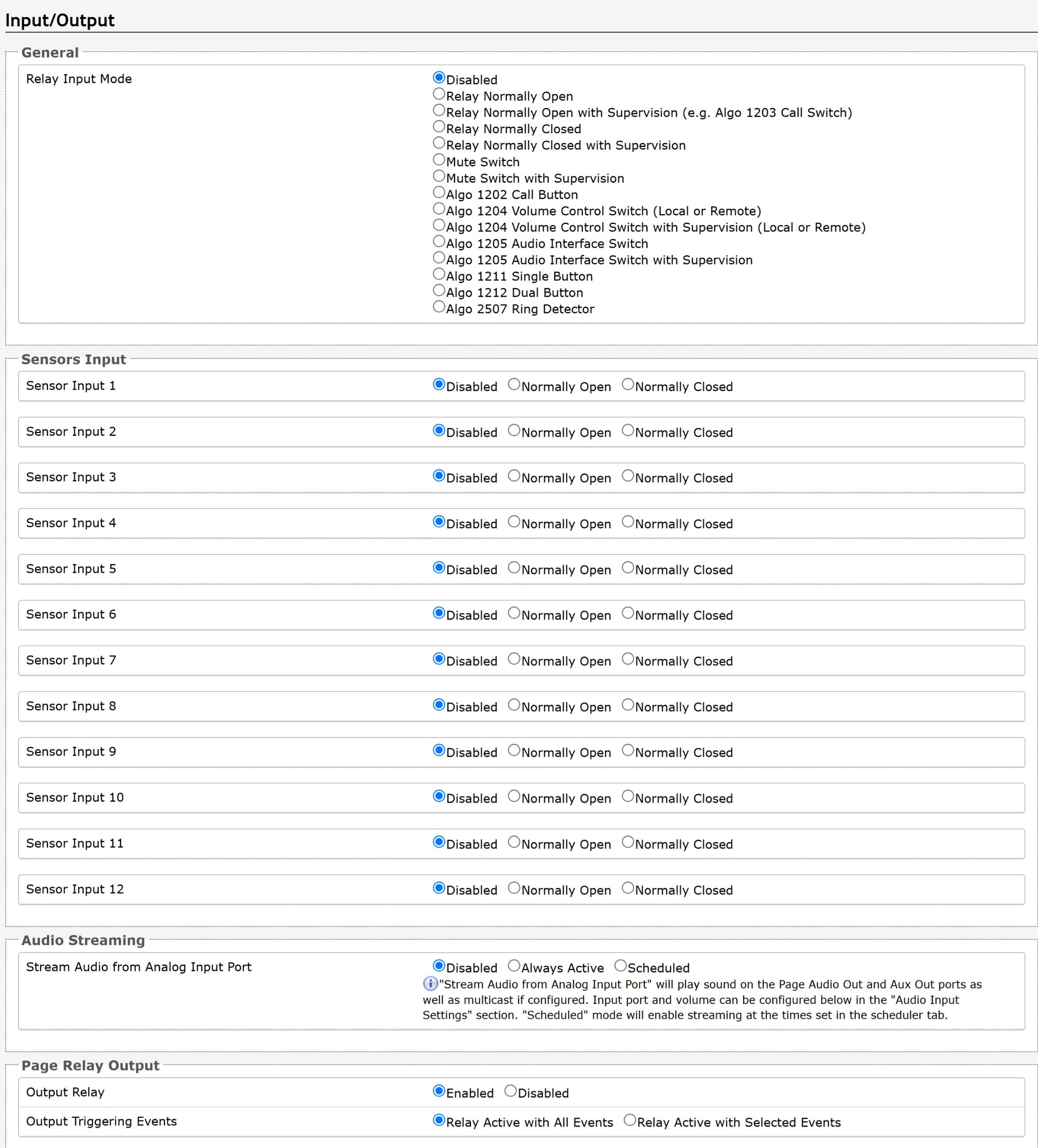
Relay Input Mode The Relay Input Mode determines how the device responds to signals from connected devices. Each mode represents a different type of input device (for example, a call button, call switch, or door sensor) and provides its own configuration options. The available Relay Input Mode options and configuration sections vary by device model and firmware version. | |
Disabled | No device is connected. The relay input is not used. |
Relay Normally Open | Connect a normally open dry contact device. When the contact closes, trigger an action. |
Relay Normally Open with Supervision (e.g. Algo 1203 Call Switch) | Connect a supervised, normally open dry-contact device, such as the Algo 1203 Call Switch. When the contact closes, trigger an action while monitoring for wiring faults. |
Relay Normally Closed | Connect a normally closed dry-contact device. When the contact opens, trigger an action. |
Relay Normally Closed with Supervision | Connect a supervised normally closed dry-contact device. When the contact opens, trigger an action while monitoring for wiring faults. |
Mute Switch | Connect a switch to mute audio output while the contact is active. |
Mute Switch with Supervision | Connect a supervised mute switch to mute audio output while monitoring for wiring faults. |
Algo 1202 Call Button | Connect an Algo 1202 call button to trigger predefined actions such as paging or alerts when pressed. |
Algo 1204 Volume Control Switch (Local or Remote) | Connect an Algo 1204 switch to adjust volume locally or remotely. |
Algo 1204 Volume Control Switch with Supervision (Local or Remote) | Connect a supervised Algo 1204 switch to adjust volume while monitoring for wiring faults. |
Algo 1205 Audio Interface Switch | Connect an Algo 1205 audio interface to trigger actions from external audio or switch input. |
Algo 1205 Audio Interface Switch with Supervision | Connect a supervised Algo 1205 interface to trigger actions while monitoring for wiring faults. |
Algo 1211 Single Button | Connect an Algo 1211 Single Button to trigger one configurable action when the button is pressed or long-pressed. |
Algo 1212 Dual Button | Connect an Algo 1212 Dual Button to trigger two configurable actions when the buttons are pressed or long-pressed. |
Algo 2507 Ring Detector | Connect an Algo 2507 ring detector to trigger actions when ringing is detected on an analog line. |
Action When Input Triggered When the Relay Input is triggered, you may activate various actions. The available actions and configuration sections vary by device model, Relay Input Mode, and firmware version. The available actions vary with your device type. | |
Action | |
Play Tone | Plays a configured tone locally on the device when the input is triggered. |
Make SIP Voice Call | Places a SIP voice call to a configured extension. |
Make SIP Call with Tone | Places a SIP call to a configured extension and plays a selected tone or pre-recorded announcement to the far end. |
Stream Mic Audio | Streams live audio from the device’s microphone to a configured destination. |
Start InformaCast Scenario | Triggers an InformaCast notification scenario for mass alerting and automated communications. |
Send API Request | Sends an HTTP/HTTPS request to a configured server for integration with external systems. |
Send SNMP Trap | Sends an SNMP trap to notify network management systems of the input event. |
Cancel Action | Cancel the ongoing action triggered by a button press. This action is available only when an Algo 1211/1212 is connected. |
Configuration Fields Common to All Actions
The following configuration fields are common to all actions.
Field | Description |
|---|---|
Send API Requests | To send API requests along with the action, set Send API Requests to Enabled and configure the desired API call. |
Send API Requests on Completion | To send API requests upon completion of the action, set Send API Requests on Completion to Enabled and configure the desired API call. |
Panic Button | Specifies whether to enable ADMP cloud monitoring for this input device. If enabled, configure the following:
|
Note
The Panic Button option is available when:
ADMP Cloud Monitoring and Panic Button Monitoring are both set to Enabled
Relay Input Mode is set to one of the following:
Relay Normally Open with Supervision (e.g. Algo 1203 Call Switch)
Relay Normally Closed with Supervision
Algo 1202 Call Button
Algo 1211 Single Button
Algo 1212 Dual Button
Configuration Fields for Buttons
If your input device has buttons, you can configure actions for the second button press, or action override.
The following configuration fields may be available.
Field | Description |
|---|---|
Allow 2nd Button Press | Specifies what happens when you press the same button again
|
Allow Same Button Press to Cancel Active Action | Specifies whether to cancel the active action when you press the same button again:
|
Allow Different Button Press to Override Active Action | Specifies what happens when there is an ongoing activity triggered by a button, what happens when you press another button:
|
"Play Tone" Configuration Fields
Field | Description |
|---|---|
Tone/Pre-recorded Announcement | Select an audio file from the Tone/Pre-recorded Announcement drop-down list. This list displays all files in the System → File Manager → tones folder. |
Audio Output | Select where the audio is sent to:
|
Tone Duration | Specifies how long the tone plays:
|
Interval Between Tones (seconds) | Specifies in seconds the wait time before the audio file plays again. |
Maximum Tone Duration | Specifies the maximum playback time. |
Use Separate Multicast | Enable this feature to allow the tone/streaming to be played via multicast even if the device is configured as a receiver, provided its Basic Receiver Zones is not set to the same multicast address. If enabled, configure the following:
|
"Make SIP Voice Call" Configuration Fields
Note
To make a SIP voice call, you must have configured the following in Basic Settings → SIP:
SIP Domain (Proxy Server)
Page Extension
Field | Description |
|---|---|
Extension to Dial | Enter the target device’s SIP extension. |
Call Mode |
|
Tone/Pre-recorded Announcement | Select Tone/Pre-recorded Announcement to play locally when using Silent Microphone Monitoring with Tone. |
Outbound Ring Limit | Sets a limit on how long the device will ring before timing out. If the call is not answered within this time period, the device will return to an idle state. |
Ringback Tone | Plays a tone locally during an outbound SIP call while waiting for the far-end party to answer. |
Maximum Call Duration | Defines the maximum length of time that a call can remain active before it is automatically terminated. |
"Make SIP Call with Tone" Configuration Fields
Note
To make a SIP voice call, you must have configured the following in Basic Settings → SIP:
SIP Domain (Proxy Server)
Page Extension
Field | Description |
|---|---|
Extension to Dial | Enter the target device’s SIP extension. |
Allow 2nd Button Press | Specifies what happens when you press the same button again
|
Tone/Pre-recorded Announcement | Select an audio file to play. |
Interval Between Tones (seconds) | Set the interval between tone playback. |
Outbound Ring Limit | Sets a limit on how long the device will ring before timing out. If the call is not answered within this time period, the device will return to an idle state. |
Audio Output | Select where the audio is sent to:
|
"Stream Mic Audio" Configuration Fields
Note
Before configuring this action, ensure your device (the host IP Endpoint) is configured as a Transmitter (Sender) under Basic Settings → Multicast → Multicast Mode.
Field | Description |
|---|---|
Audio Output | Configure where the audio is output to:
|
Use Separate Multicast | Enable this feature to allow the tone/streaming to be played via multicast even if the device is configured as a receiver, provided its Basic Receiver Zones is not set to the same multicast address. If enabled, configure the following:
|
"Send API Request" Configuration Fields
Field | Description |
|---|---|
Number of API Requests | Specify how many API requests to send. |
Command | Select a REST API command from the Command drop-down list. |
Data Payload | Data to be sent in the request body. |
Target | One or more destination device IP addresses or application URLs (comma-delimited). For example,
|
Method | Choose the HTTP method ( |
Custom Path | Enter the custom API endpoint path. For example,
|
Header | Provide required headers. For API calls to Algo devices, select Algo Standard Authentication Headers. For non-Algo devices, select and specify Custom Headers. For example, |
Related Links:
"Send SNMP Trap" Configuration Fields
Note
Send SNMP Trap on Release is available only when the relay input mode is configured as:
Normally Open
Normally Closed
Normally Open with Supervision
Normally Closed with Supervision
You must enable and configure Simple Network Management Protocol in Advanced Settings → Admin before using this action.
Field | Description |
|---|---|
Send SNMP Trap on Release | To send a second SNMP trap when the relay input is released, enable Send SNMP Trap on Release. This sends trap OID value 5 (Relay input idle). For SNMPv1 , a prefix of 6 is added indicating an enterprise-specific trap. |
"Start InformaCast Scenario" Configuration Fields
Note
The Start InformaCast Scenario action is available only when InformaCast Scenarios API is enabled under Advanced Settings → Admin → InformaCast Scenarios API.
Before configuring this action, ensure you have configured an InformaCast Scenario and obtained its ID.
Field | Description |
|---|---|
InformaCast Scenario ID | Enter the InformaCast Scenario ID. |
Emergency Alerts Settings
The Emergency Alerts page allows you to configure SIP-triggered emergency announcements and alert behavior. You can define how announcements are activated and cancelled, configure authentication and passcode protection, select announcement audio sources, and specify multicast destinations and API requests to support emergency notification workflows.
For more information, see Configuring Emergency Announcements.
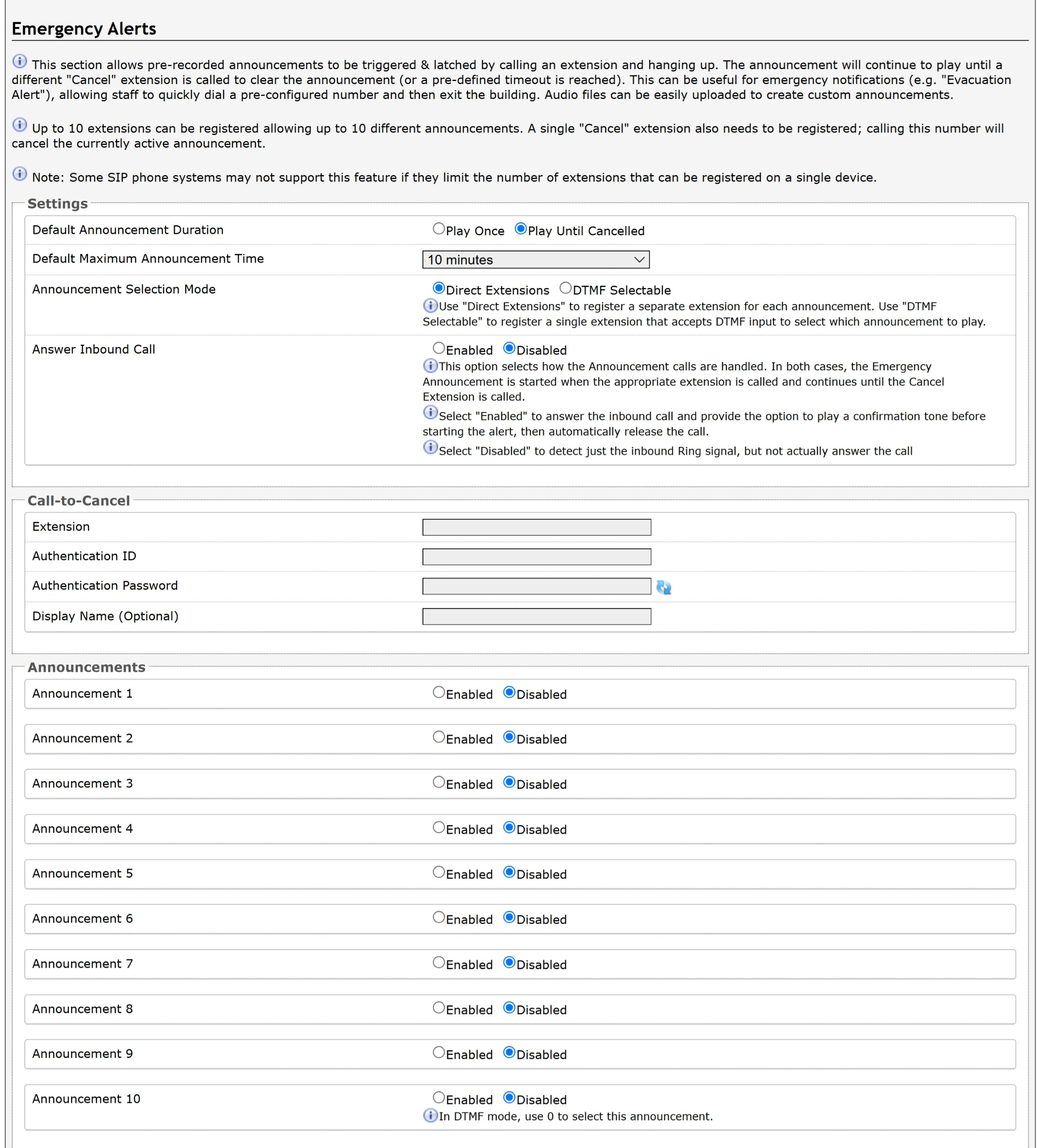
General Settings
General Settings controls how the announcement plays and how to trigger it.
Settings | Description |
Default Announcement Duration | An announcement can be played once or continuously until canceled.
|
Default Maximum Announcement Time | Select the maximum time an announcement will play for. |
Audio Input Port | Select the audio source:
This Audio Input Port option is available only if <Use Audio Input Port> is selected for the Tone/Pre-recorded Announcement setting of at least one Announcement under Additional Features → Emergency Alerts. |
Announcement Selection Mode | Select how to trigger the announcement:
|
Answer Inbound Call | This option selects how the Announcement calls are handled. In both cases, the Emergency Announcement is started when the appropriate extension is called and continues until the Call-to-Cancel Extension is called.
|
Passcode Protected Announcement Extensions | Select Enabled to require the caller to enter a passcode after dialing an announcement or Call-to-Cancel extension. Setting a passcode helps prevent unintentional announcements. |
Announcement Passcode | Enter a passcode that a caller must enter to play or cancel an announcement. When prompted, the caller must enter the passcode followed by the # sign before the announcement will be played or canceled. The passcode prompt will be played before any other action. If the passcode is not correctly entered within 15 seconds, the call will end, and there will be no change to the current announcement state. |
DTMF Selection
DTMF extension will be used to activate and optionally cancel emergency alerts when Announcement Selection Mode is set to DTMF Selectable. Use the configurations below to register a single extension that will accept DTMF input to play selected announcements.
Settings | Description |
Extension | Enter the SIP extension for the DTMF Selection parameter. The device will auto-answer any inbound call received on this extension and provide a voice paging path (and multicast if configured). |
Authentication ID | Enter the Authentication ID. The Authentication ID may also be called Username for some SIP servers and in some cases may be the same as the ring and/or page extension. |
Authentication Password | Enter the SIP password provided by the system administrator for the SIP account. |
Display Name (Optional) | Enter a Display Name that will be sent when the SIP call is made. The PBX and phone(s) must be configured to display this message as the Caller ID. |
Prompt Tone | Select a tone to play when the passcode is ready to be entered. |
Call-to-Cancel
When your Algo device uses SIP for emergency alerts, both a start trigger (Announcement) and stop trigger (Call-to-Cancel) must be configured.
Settings | Description |
Call-to-Cancel Selection Mode | If using “DTMF 0”, the user should dial the main DTMF Selection extension and select ‘0’ to cancel the announcement. Using DTMF 0 allows emergency alerts to work with only a single SIP registration rather than requiring multiple accounts. |
Extension | Enter the SIP extension for the Call-to-Cancel Selection parameter. The device will auto-answer any inbound call received on this extension and provide a voice paging path (and multicast if configured). |
Authentication ID | Enter the Authentication ID provided by the system administrator. For some SIP servers, it may also be called the Username or the same as the extension. |
Authentication Password | Enter the SIP password provided by the system administrator for the SIP account. |
Display Name (Optional) | Enter a Display Name that will be sent when the SIP call is made. The PBX and phone(s) must be configured to display this message as the Caller ID. |
Confirmation Tone | Select a tone to play to confirm that an alert has been canceled. |
Announcements
Up to 10 extensions can be registered, allowing up to 10 different announcements. Audio files can also be easily uploaded to create custom announcements. Only one Call-to-Cancel extension is needed, despite the number of the alert extensions.
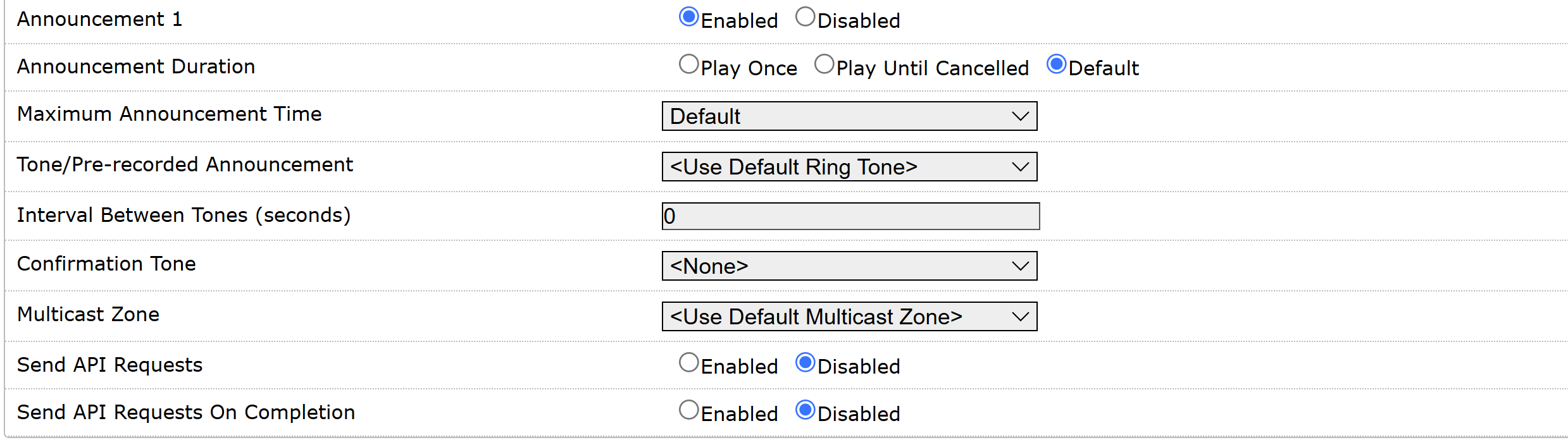
Note
Some SIP phone systems may not support this feature if they limit the number of extensions that can be registered on a single device.
Settings | Description |
Announcement # | To configure an Emergency Alert extension, select Enabled for an announcement number. Up to 10 extensions can be registered, allowing up to 10 different announcements. Audio files can be easily uploaded to create custom announcements. Only one Call-to-Cancel extension is needed. Alternatively, DTMF Selectable Mode can be used if the SIP telephone system limits the number of extensions that can be registered on a single device. |
Announcement Duration | Choose the duration of an announcement:
|
Maximum Announcement Time | Select the maximum announcement time. |
Tone/Pre-recorded Announcement | Select a file or audio input to use as the announcement:
|
Interval Between Tones (seconds) | Specify the interval between tone playbacks, in seconds. |
Confirmation Tone | Select a file to use as a confirmation tone. This option is available when Answer Inbound Call is enabled. |
Multicast Zone | Set the RTP multicast zone where announcements will be played. |
Multicast Poly Group | Set the Poly Group where announcements will be played. This option is available only when your Multicast Type is set to one of the following:
|
Send API Requests | When the announcement starts, send up to five REST API requests to external devices or systems to trigger specific functions or behaviors. |
Send API Requests On Completion | When the announcement ends, send up to five REST API requests to external devices or systems to trigger specific functions or behaviors. |
Related Links:
Network Settings
Network Settings configure how the device connects to your IP network, including IP addressing (DHCP or static), DNS, and IPv4/IPv6 settings. These settings ensure the device can communicate with SIP servers, cloud services, and other network resources.
Note
Available settings may vary depending on your product model and firmware version.
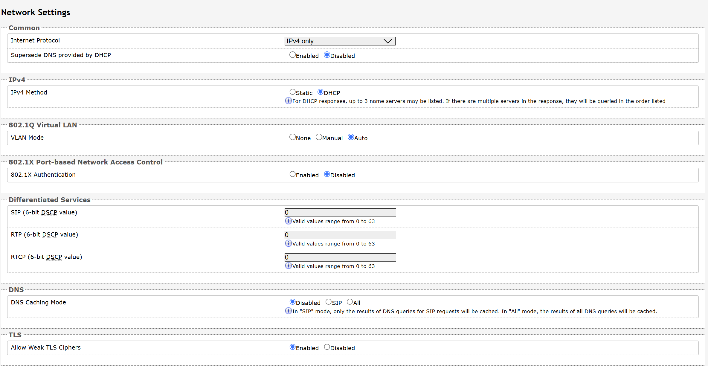
Common | |
Internet Protocol | Use the dropdown to select IPv4 Only or IPv4 and IPv6. |
Supersede DNS provided by DHCP | When enabled, this configuration allows DNS settings to be manually configured, replacing ones that may have been provided via DHCP. |
IPv4 | |
IPv4 Method |
|
IPv4 Address/Netmask | Enter the static IP address and netmask (CIDR format) for the device (e.g., 192.168.1.23/24 where “/24” is equivalent to a netmask of 255.255.255.0). |
IPv4 Gateway | Enter the gateway address. |
IPv6 | |
IPv6 Method | The device can be set to a static or DHCP IP address. |
IPv6 Address/Netmask | Enter the static IP address and netmask (CIDR format) for the device (e.g., 2001:123::abcd:1234/64). |
IPv6 Gateway | Enter the gateway address. |
ICMPv6 Options | |
Destination Unreachable Messages | Enable to restrict traffic by filtering ICMPv6 packets. |
Neighbor Discovery Redirect Messages | Enable to restrict traffic by filtering ICMPv6 packets. |
Anycast Echo Replies | Enable to restrict traffic by filtering ICMPv6 packets. |
Enable Rate Limiting Outbound Messages | Enable to limit the device to respond to other network devices at the specified rate below and prevent it from receiving multiple requests at the same time. |
Rate Limit (packets per second) | Specify the packets per second allowed for Rate Limiting Outbound Messages. |
802.1Q Virtual LAN If the device is using VLAN, you will need to be on the same VLAN to access the web interface, unless routing has been configured between VLANs. | |
VLAN Mode | None: Disable VLAN. Manual: Configure a VLAN by specifying its ID and frame priority. Auto: Detect VLAN information automatically and tag outgoing traffic accordingly. |
VLAN ID | Specify the VLAN that the Ethernet frame belongs to. The hexadecimal values 0x000 and 0xFFF are reserved. All other values may be used as VLAN identifiers, allowing up to 4094 VLANs. |
VLAN Priority | Set the frame priority level. Otherwise known as Priority Code Point (PCP), VLAN Priority is a 3-bit field that refers to the IEEE 802.1p priority or frame priority level. Values are from 0 (lowest) to 7 (highest). |
802.1X Port-based Network Access Control | |
802.1x Authentication | Enable to add credentials to access LAN or WLAN that have 802.1X network access control (NAC). You can ask your IT Administrator for this information. |
Authentication Mode | Select the desired authentication mode. |
Anonymous ID | If configured, the device will send the anonymous ID to the authenticator instead of the 802.1X client username. |
ID | The ID should contain a string identifying the IEEE 802.1X authenticator originating the request. Ask your IT Administrator for details. |
Password | Ask your IT Administrator for details. |
Validate Server Certificate | Enable to validate the authentication server against common authorities. To validate additional certificates, go to the System → File Manager to upload a Base64 encoded X.509 certificate file in .pem, .cer, or .crt format to the certs folder. |
Differentiated Services | |
SIP (6-bit DSCP value) | Enter the Differentiated Services Code Point (DSCP) value for SIP packets. |
RTP (6-bit DSCP value) | Enter the DSCP value for RTP packets. |
RTCP (6-bit DSCP value) | Enter the DSCP value for RTCP packets. |
DNS | |
DNS Caching Mode | There are three mode options:
|
TLS | |
Allow Weak TLS Ciphers | Enables compatibility with legacy systems that may not support the most current encryptions standards. |
Admin Settings
Admin settings allow you to configure device access, security, management, monitoring, and integration features.
From this page, you can change administrator credentials, manage logging and network management settings, enable APIs and external services, and configure device maintenance options.
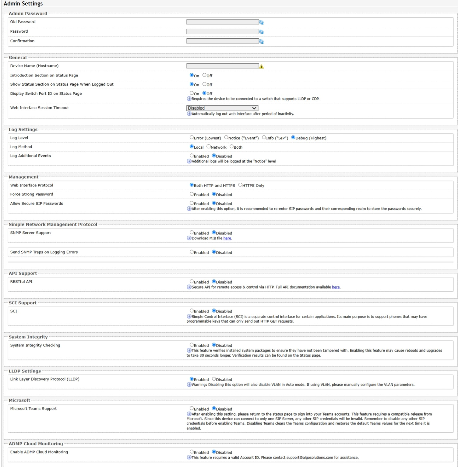
Admin Password | |
Old Password | Enter the old admin password. The default password when you first get the device is algo. |
Password | Enter a new admin password to log into the device web interface. Make sure the new password is stored safely. If the password is forgotten, you must reset the device entirely with the Reset Button to restore the default password. All other settings will be reset to the original default settings as well. To reset the device using the button, see Restoring Factory Default Settings Only. |
Confirmation | Re-enter your new admin password. |
General | |
Device Name (Hostname) | Add a name to identify the device. |
Introduction Section on Status Page | Select On to show the introduction text on the login screen. |
Show Status Section on Status Page when Logged Out | Select On to allow others to view the status page without logging in. Select Off to hide the settings and configurations on the status page unless a user is logged in to ensure only trusted users can view device information. |
Display Switch Port ID on Status Page | Select On to display the Switch Port ID on the Status Page. This option is only possible if the device is connected to a switch that supports LLDP or CDP. |
Web Interface Session Timeout | Set the maximum duration of inactivity to log a user out of the web interface automatically. |
Play Tone at Startup | The device can play a beep tone at startup. This option is available only to Algo IP Speakers, IP Displays, Paging Adapters, and IP Consoles. |
Log Settings | |
Log Level | Select the types of information you want to include in the system log files.
|
Log Method | Select a log method: Local: The log file is saved in RAM on the device. Network: Send the log file to an external SysLog server so settings are not lost if the device is rebooted, or for ease of central access. Both: Use both methods. |
Log Server | Enter the Syslog server address provided by your IT administrator. |
Log Additional Log Events | To be used by support@algosolutions.com if necessary. |
Management | |
Web Interface Protocol | HTTPS is always enabled on the device. HTTP is enabled by default but may be disabled. To do so, select HTTPS Only mode so requests are automatically redirected to HTTPS.
|
Force Strong Password | When Enabled, you can enforce a secure password for the device web interface for additional protection. The password requirements for a strong password are:
|
Allow Secure SIP Passwords | When Enabled, SIP passwords are stored in the configuration file in an encrypted format to prevent viewing and recovery. If enabled, navigate to Basic Settings → SIP and fill out the Realm field. To obtain your SIP Realm information, contact your SIP Server administrator or check the SIP log file for a registration attempt. The Realms may be the same or different for all the extensions used. All the configured Authentication Password(s) must be re-entered here as well as any other locations where SIP extensions have been configured to save the encrypted password(s). If the Realm is changed later, all passwords must be re-entered to save the passwords with the new encryption. |
Simple Network Management Protocol | |
SNMP Support | Disabled by default. The existing setting will respond to a simple status query for automated supervision. |
Send SNMP Traps on Logging Errors | When enabled, the device sends unsolicited SNMP trap notifications when logging errors occur. |
SNMP Community String | Speak to your IT Administrator for more information. |
SNMPv3 Security | Speak to your IT Administrator for more information. |
API Support | |
RESTful API | Disabled by default. Enable a secure API for remote access and device control via HTTP. For more information, see Algo RESTful API Guide. |
Authentication Method | Select an option:
|
RESTful API Password | Authentication requires generating a valid HMAC signature using the provided RESTful API Password. The device verifies this signature before processing your API command. For more information, see the Algo RESTful API Guide or speak to your IT Administrator. |
SCI Support | |
SCI | Disabled by default. Simple Control Interface (SCI) is a separate control interface for certain applications. Its primary purpose is to support phones that may have programmable keys that can only send out HTTP GET requests and allow them to initiate events remotely on an Algo device. |
SCI Password | Enter your SCI password. |
System Integrity | |
System Integrity Checking | Enable this feature to verify that installed system packages have not been tampered with by running a check. Enabling this feature may cause reboots and upgrades to take 30 seconds longer. Verification results can be found on the Status tab. |
Power over Ethernet | |
PoE Power Detection | Use Force PoE+ only when connected to a PoE+ power injector capable of providing 600mA that does not automatically negotiate its power capabilities. Incorrect use of this setting may cause the device to reboot if the power source is not capable of delivering the selected power. |
Note
The Power over Ethernet configuration section is available only on devices that require a PoE+ power source.
LLDP Settings | |
Link Layer Discovery Protocol (LLDP) | Enables LLDP to exchange network configuration information with the connected network switch. |
Use LLDP for Power Negotiation | Determines whether the device uses LLDP to communicate its PoE power requirements to the connected network switch. This setting is available only on devices that require a PoE+ power source. |
Note
Disabling Link Layer Discovery Protocol (LLDP) prevents your device from exchanging network configuration information with the connected network switch. If you are using a VLAN, make sure Link Layer Discovery Protocol (LLDP) is enabled, or that the VLAN Mode (under Advanced Settings → Network Settings) is set to Manual so you can configuration VLAN settings manually.
Intrado OneAlert | |
OneAlert Support | Enable the device to register with an Intrado OneAlert server and receive audio events from the system. |
OneAlert Server | Enter the OneAlert Server to use the Revolution paging feature. Leave the field blank to use the server provided by the DHCP Option 72. |
Local Management Port | Enter the local management port for the Revolution Server. |
Note
The Intrado OneAlert feature is available only to Algo IP Speakers, IP Paging Adapters, IP Displays, and IP Visual Alerters.
InformaCast IP Speaker Enable your device to register as an InformaCast SIP endpoint. This allows it to initiate and receive SIP calls and receive messages through InformaCast. | |
InformaCast IP Speaker Support | This feature requires a valid InformaCast license to be activated. Please contact sales@algosolutions.com for assistance. |
Configuration Mode | Auto: The device will attempt to configure Informacast using DNS SRV, SLP, and/or via DHCP and TFTP Manual: The device will allow the configuration file location to be manually configured. Direct: The device will register to the list of static server addresses directly, bypassing the Configuration File Server |
Configuration Retry Interval | Set the amount of time to wait before attempting to obtain configuration information after failure. |
SIP Support | Enter the SIP credentials provided by InformaCast during configuration. |
Maximum Broadcast Duration | The maximum length of broadcast. |
Note
This feature requires a valid license to be activated. Please contact sales@algosolutions.com for assistance.
The InformaCast IP Speaker feature is available only to Algo IP Speakers, IP Visual Alerters, IP Paging Adapters, IP Displays, and IP Consoles.
For more information, see Singlewire InformaCast Integration Guide.
InformaCast Scenarios API | |
InformaCast Scenario API Support | Enable the device to start an InformaCast Scenario via relay input. This feature can work without an InformaCast license, as only the output device requires a license. |
Security Token | Enter the Security Token used for authenticating API requests with the InformaCast system. |
Include Location | Enable this option to include the device’s location in the scenario trigger request. |
Microsoft | |
Microsoft Teams Support | Enable to allow the device to register with a Microsoft Teams account. The device reboot will take up to 5 minutes to complete, as the device will communicate several times with the Microsoft server. This feature requires a compatible release from Microsoft. After enabling this setting, please return to the Status page to sign into your Teams accounts. This feature requires a compatible release from Microsoft. For more details, please see the Microsoft Teams Configuration Guide. |
ADMP Cloud Monitoring | |
Enable ADMP Cloud Monitoring | The Algo Device Management Platform (ADMP) simplifies the process of managing, monitoring, and maintaining Algo devices from any location. This feature requires a valid Account ID. To learn more about ADMP and how to purchase a license, visit the ADMP webpage. |
Account ID | Enter the account ID listed on the Settings page of your ADMP account. |
Allow Configuration File Sync | Enable ADMP to query and display settings stored on the device. |
Heartbeat Interval | Select how often ADMP should check the status of your device. |
Enable Panic Button Monitoring | Enable to monitor Panic Button status in ADMP, including:
|
Time Settings
Time configures the device's date, time, time zone, and Network Time Protocol (NTP) settings to ensure accurate timekeeping and proper scheduling of time-based features.
Network time is used for logging events into memory for troubleshooting.
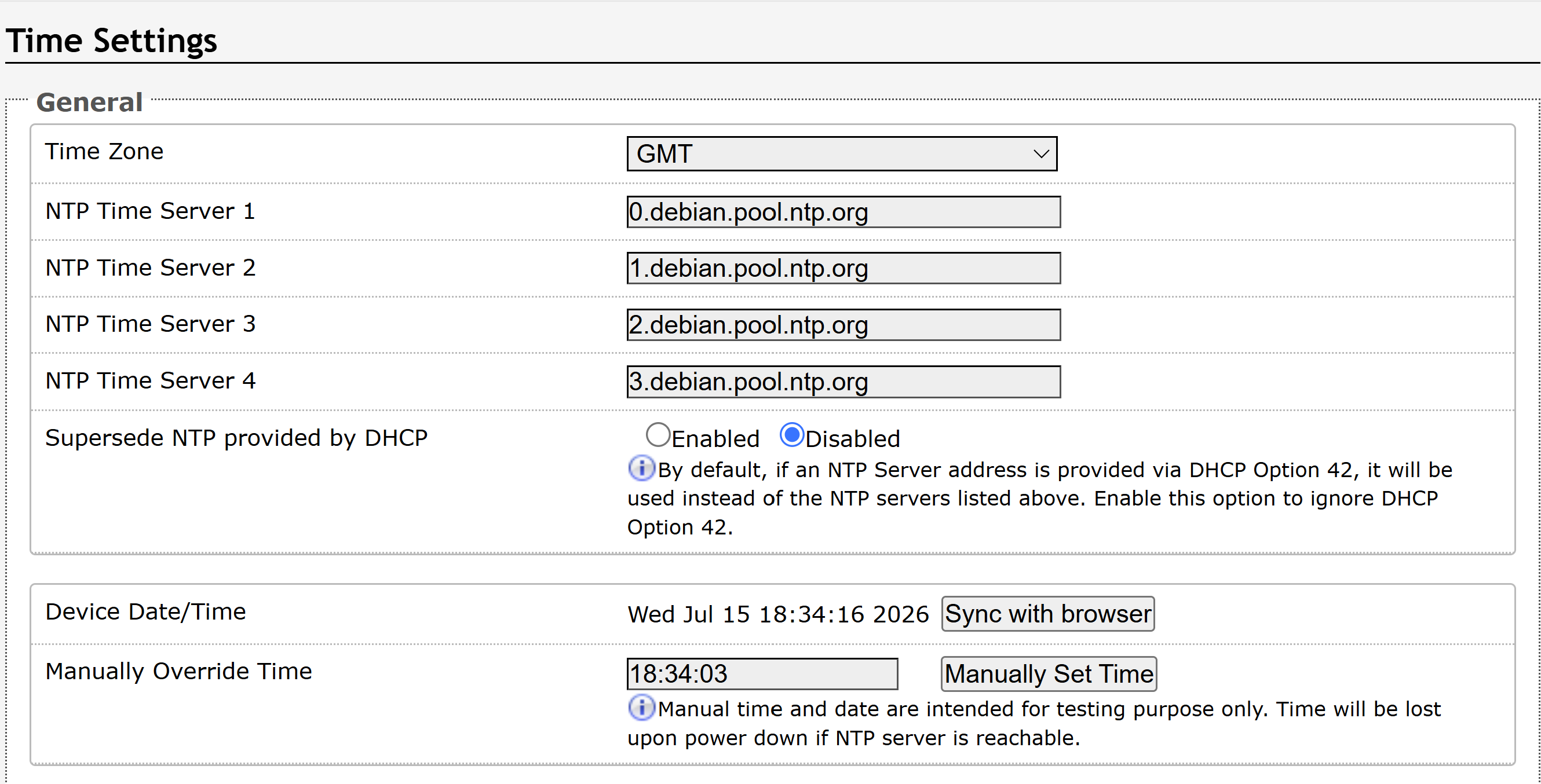
Time Settings | |
Time Zone | Use the dropdown to select the time zone required for your device. |
NTP Time Server | The interface will attempt to use Time Server 1 and work down the list if one or more of the time servers become unresponsive. These settings are pre-populated with public NTP servers hosted on the internet. To use these, the device requires an internet connection. Alternatively, this can be customized to point the device to any other NTP server hosted or premise-based. |
Supersede NTP provided by DHCP | By default, if an NTP Server address is provided via DHCP Option 42, it will be used instead of the NTP servers listed above. Enable this option to ignore DHCP Option 42. |
NTP Symmetric Key Authentication | To enable, create a new folder in the tab System → File Manager and create a folder named ntp. Upload the symmetric key file and rename the file to ntp.keys. |
Device Date/Time | This field shows the current time and date set on the device. If you are testing the device on a lab network that does not have access to an external NTP server, click Sync with browser to temporarily set the time on the device. This time value will be lost at power down or overwritten if a connection to the NTP server is available. Time and date are used for logging purposes. |
Manually Override Time | Manual time and date are intended for testing purposes only. Time will be lost upon power down if the NTP server is reachable. |
Provisioning Settings
Provisioning configures automatic device provisioning, allowing the device to retrieve configuration files and updates from a remote provisioning server.
Fore more information, see Central Provisioning of Algo IP Endpoints.
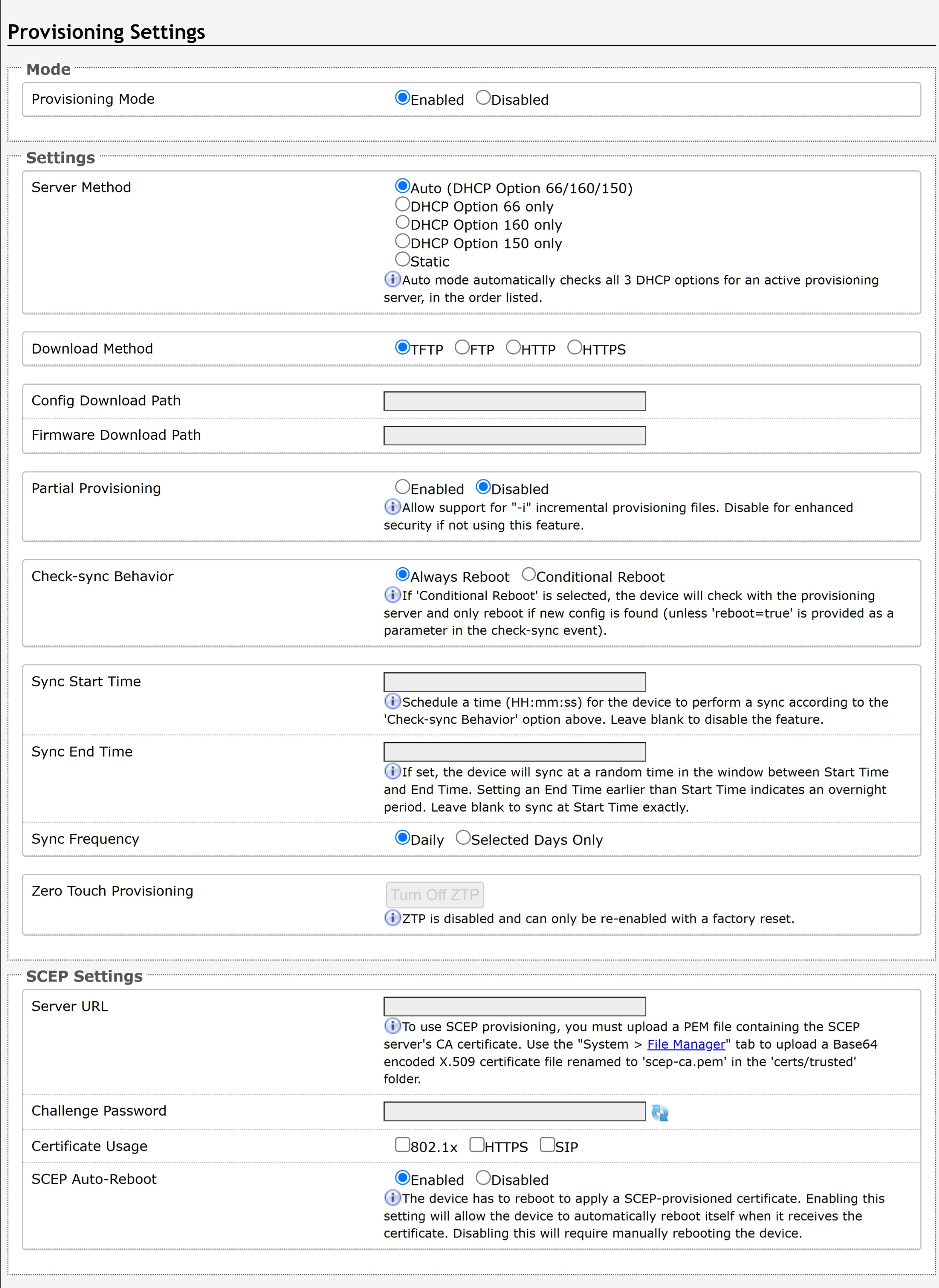
Note
It is recommended that Provisioning Mode be set to Disabled if this feature is not in use. This will prevent unauthorized re-configuration of the device if DHCP is used.
Mode | |
Provisioning Mode | Enabling provisioning allows installers to pre-configure the device on a network before installation. This is typically done for large deployments to save time and ensure consistent setups. |
Settings | |
Server Method | Set to Auto by default. Select a Server Method.
For provisioning to work with a DHCP option, DHCP must be enabled under Advanced Settings → Network → IPv4. |
Static Server | Enter the server address or domain. |
Download Method | Select your preferred method for downloading provisioning files. The options are:
The device configuration files can be automatically downloaded from a provisioning server using DHCP Option 66. This option code (when set) supplies a TFTP boot server address to the DHCP client to boot from.
Both protocol and path are supported for Option 66, allowing for http://myserver.com/config-path to be used. |
Config Download Path | Enter the path where the configuration file is located in the provisioning server (e.g., algo/config/8312). |
Firmware Download Path | Enter the path where the configuration file is located in the provisioning server (e.g., algo/config/8312). |
Partial Provisioning | Enable to allow support for “-i” incremental provisioning files. Disable for enhanced security if this is not required. |
Check-sync Behavior | Select Always Reboot to set the device to always reboot despite other settings. |
Sync Start Time | Set a time (HH:MM:SS) for the device to perform a sync according to the Check-sync Behavior setting. Leave this blank if not needed. |
Sync End Time | If set, the device will sync randomly in the window between Sync Start Time and Sync End Time. Setting an End Time earlier than the Start Time indicates an overnight period. Leave blank to sync exactly at the set start time. |
Sync Frequency | Select the sync frequency. Frequency can be set to Daily or Selected Days Only. |
Sync Days | Select the days of the week for syncs to occur. |
Zero Touch Provisioning | ZTP is enabled by default, allowing the device to automatically fetch its configuration on first boot from the provisioning server.
|
Advanced Audio Settings
Advanced Audio configures advanced audio processing and media settings to optimize audio quality, reliability, and compatibility.
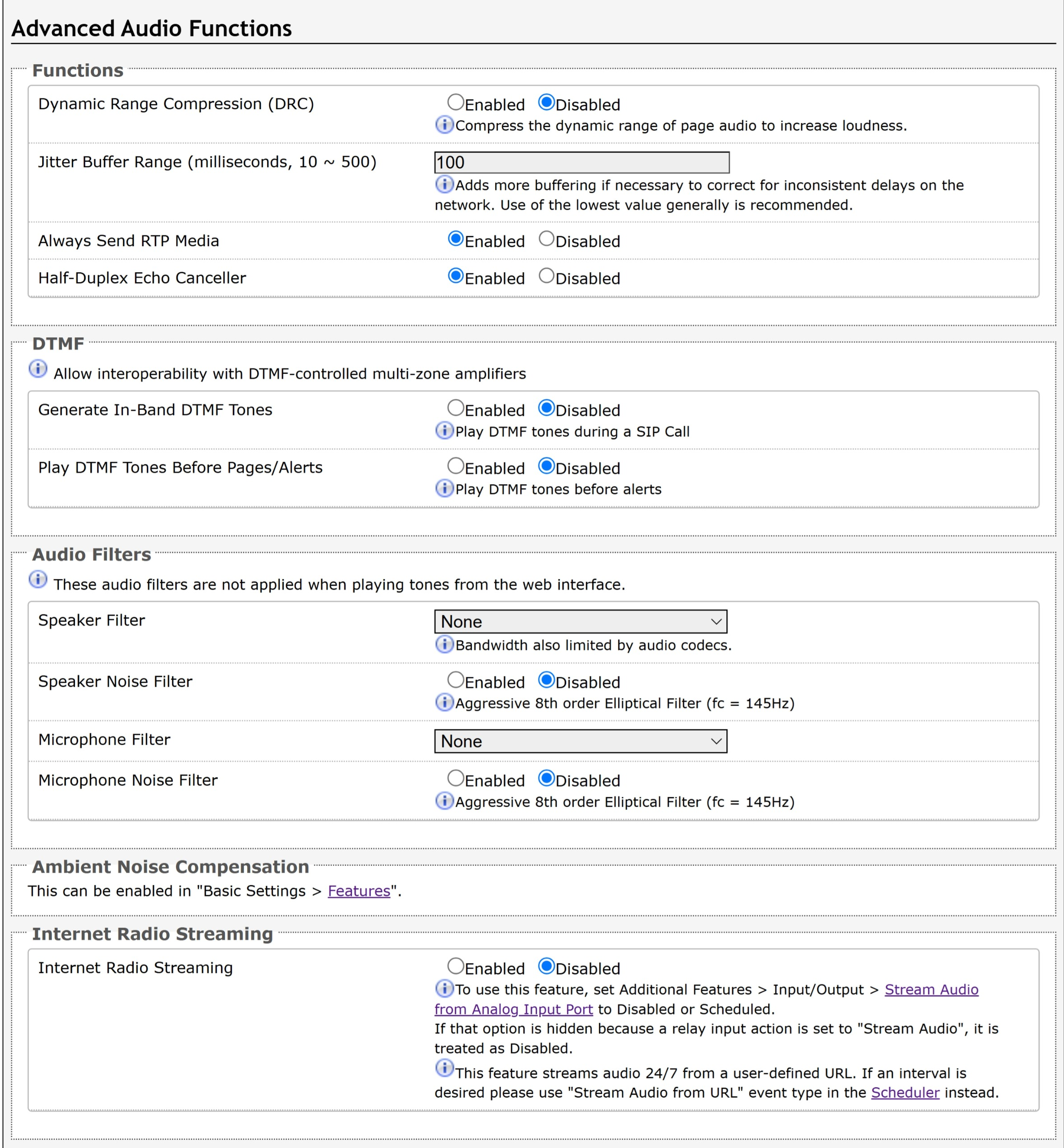
Functions | |
Dynamic Range Compression (DRC) | Enable to compress the dynamic range of page audio to increase loudness. |
Dynamic Range Compression Gain | Select the amount of compression gain from the dropdown menu. Higher gain levels may introduce more distortion. |
Jitter Buffer Range | Enter a value between 10-500 to add more buffering if necessary to correct for inconsistent delays on the network. It is recommended to use the lowest value. Using unnecessarily high values may introduce audio delay or latency. |
Always Send RTP Media | Enable to send audio packets at all times, even during one-way paging mode. This option is needed when the server expects to always see audio packets. |
Half-Duplex Echo Canceller | Enable to reduces acoustic echo during two-way conversations by suppressing echo from the speaker while the microphone is active. |
DTMF When amplifiers are connected to the AUX OUT port, some may require DTMF to select broadcast zones. DTMF tones are supported in the following events:
You can configure the same global DTMF tone(s) for all events or set tones per event. For more information, see Playing DTMF Tones Before Paging or Alerts. | |
Generate In-Band DTMF Tones | Enable to play DTMF tones during an SIP call to allow interoperability with DTMF-controlled multi-zone legacy communication systems. |
Play DTMF Tones Before Pages/Alerts | Select whether to play DTMF tones before alerts. |
DTMF Tone(s) | Configure a DTMF tone for this paging number. |
Global DTMF Tone(s) | Set the same global DTMF tone(s) for all paging, ringing, and Emergency Alerts so that the same broadcast zones are used for all events. |
DTMF Tone Duration | Select how long the DTMF tone plays. |
Audio Filters | |
Speaker Filter | Select a frequency from the dropdown to apply a high-pass filter to the speaker output. This setting reduces audio artifacts like humming or buzzing by filtering out unwanted frequencies. |
Speaker Noise Filter | Enable filtering below 145 Hz to reduce mains-induced noise like fans. |
Microphone Filter | Select a frequency from the dropdown to apply a high-pass filter to the microphone input. This setting reduces audio artifacts like humming or buzzing by filtering out unwanted frequencies. |
Microphone Noise Filter | Enable filtering below 145 Hz to reduce mains-induced noise like fans. |
Microphone | |
Global Microphone Mute | Enable to disable the microphone entirely. |
Microphone Volume | Select a volume for the microphone. |
Display | |
Power Levels | Enable to display audio power levels in Ring/Alert Volume and Page Volume drop-down lists (in Basic Settings → Features ). This will show the maximum power in Watts when a full-scale input signal is used (e.g., 1kHz sine wave, with an RMS level of -3dBFS). This allows for an easy level comparison ith legacy analog products or other Algo products that support PoE+ or satellite speakers. |
Ambient Noise Compensation Only available if Ambient Noise Compensation is Enabled in Basic Settings → Features. | |
Ambient Noise Compensation No Loss |
|
Ambient Noise Compensation Max Volume | Based on ambient noise levels, a maximum volume can be set. |
Internet Radio Streaming
For more information, see Streaming Music from Online URL or Offline Audio File. | |
Radio Volume | Set the audio output volume for the AUX OUT port. This volume doesn’t impact the multicast volume of the receiving devices. |
Radio URL | Enter the stream URL. |
Offline Music File | Select an audio file to stream. Make sure you have upload at least one offline music file to the System → File Manager → Radio folder. |
Multicast Zone | Select a zone to multicast the audio to. Your device must be configured as a multicast transmitter first. The multicast output is RTP-only, using the L16 codec with a fixed packet size. If you select <Use Default Multicast Zone>, zone specified in Basic Settings → Transmitter (Sender) Zone Settings → Transmitter Single Zone is used. |
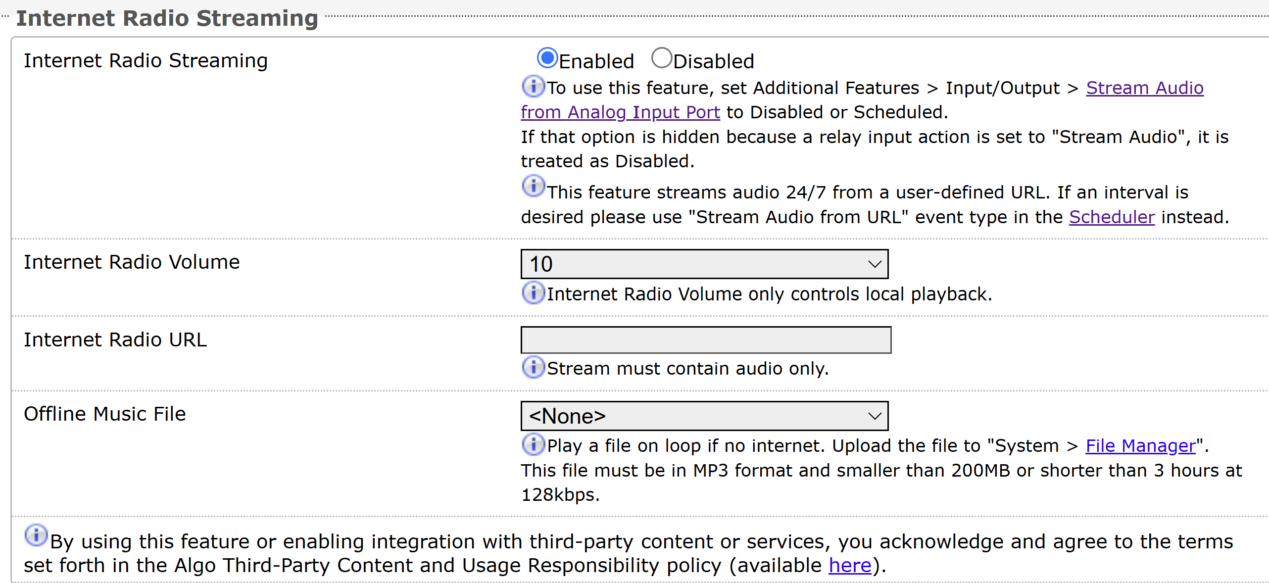
Advanced SIP Settings
Advanced SIP configures advanced SIP communication settings, such as registration, session timers, transport, codecs, and other protocol options to optimize interoperability and call performance.
General | |
SIP Transportation | Select a transport layer protocol to use for SIP messages from the dropdown. These options include:
|
SIPS Scheme | Only visible when SIP Transportation is set to TLS. Enable to require the SIP connection from endpoint to endpoint to be secure. |
Validate Server Certificate | Enable validation of the SIP server against common certificate authorities. To validate additional certificates, navigate to System → File Manager to upload a Base64 encoded X.509 certificate file in .pem, .cer, or .crt format to the certs folder. |
SIP Outbound Support (RFC 5626) | Enable this option to support best networking practices according to RFC 5626. This option should be enabled if the device is registered with a hosted server or TLS is used for SIP Transportation.
|
Outbound Proxy | Enter the IP address for an outbound proxy. |
Register Period (seconds) | Enter the maximum requested period that the device will re-register with the SIP server. The default setting is 3600 seconds (1 hour).
|
Rate Limit SIP Registration | This option should be used in cases where many SIP extensions are registered (ex. one for each zone). Select a rate limit to stagger registration requests and prevent overloading the server by sending them all at the same time. |
Wait for Successful Unregister | Enable to wait for the device to successfully unregister from the server. Enabling may cause a slight delay during configuration changes and reboots. |
Allow Second Call on Ring Extension | When enabled, a second call on the Ring Extension will replace the current ringing call instead of receiving a "busy" response. |
SRTP | |
SDP SRTP Offer | Select an option from the dropdown menu:
|
SDP SRTP Offer Crypto Suite | The encryption and authentication algorithms are used for voice data. |
NAT | |
Media NAT | None: Disable NAT. ICE: Enable advanced NAT support. STUN: Enable basic NAT support. |
TURN Server | Enter the IP address or domain of the ICE server. |
TURN User | Enter the username of the ICE server. |
TURN Password | Enter the password of the ICE server. |
STUN - Server | Enter the IP address or domain of the STUN server. |
Server Redundancy | |
Server Redundancy Feature | Enable to configure up to two secondary backup SIP servers. When enabled, the device will attempt to register with the primary server but switch to a secondary server when necessary. The configuration allows re-registration to the primary server upon availability or to stay with a server until unresponsive. |
Backup Server #1, #2 | Provided by your SIP provider or IT team. |
Polling Intervals (seconds) | Select the time interval for sending monitoring packets to each server from the dropdown menu. Inactive servers are always polled and the active server may optionally be polled. |
Poll Active Server | Enable to explicitly poll the current server to monitor availability. Other regular events may also handle this automatically and can be disabled to reduce network traffic. |
Automatic Fallback | Enable to allow the device to reconnect with a higher priority server once available, even if the backup connection is still working. |
Polling Method | Select a polling method based on what your SIP provider supports. |
Zoom Phone Local Survivability | |
|---|---|
Local Survivability | Enable re-registration with the local Zoom Phone Local Survivability (ZPLS) Node if connection to Zoom fails. This allows sites to maintain a subset of Zoom Phone features even if connectivity to the Zoom Phone cloud is lost.
|
Survivability Proxy | Enter the IP address or domain name of the local Zoom Phone Local Survivability (ZPLS) node. |
Interoperability | |
Keep-Alive Method | Select a keep-alive method:
|
Keep-Alive Interval (seconds) | Set the interval in seconds that the CRLF message should be sent. 30 seconds is recommended. |
Use Outgoing TLS port in SIP Headers | Enable to use of the ephemeral port number from an outgoing SIP TLS connection instead of the listening port number in SIP Contact and Via headers. This is useful for connecting the device to some local SIP servers, such as Asterisk or FreeSWITCH. |
Do Not Reuse Authorization Headers | Enable so all SIP authorization information from the last successful request will not be reused in the next request. |
Allow Missing Subscription-State Headers | Enable to allow SIP NOTIFY messages that do not contain a ‘Subscription-State’ header. |
Add MAC in SIP User Agent Header | Specifies whether to include the device’s MAC address in the SIP |
Advanced Multicast Settings
These settings are only visible when in Transmitter or Receiver multicast mode. This can be set in Basic Settings → Multicast. The default pre-populated multicast zone IP addresses and ports will work in most cases and should only be altered for rare cases.
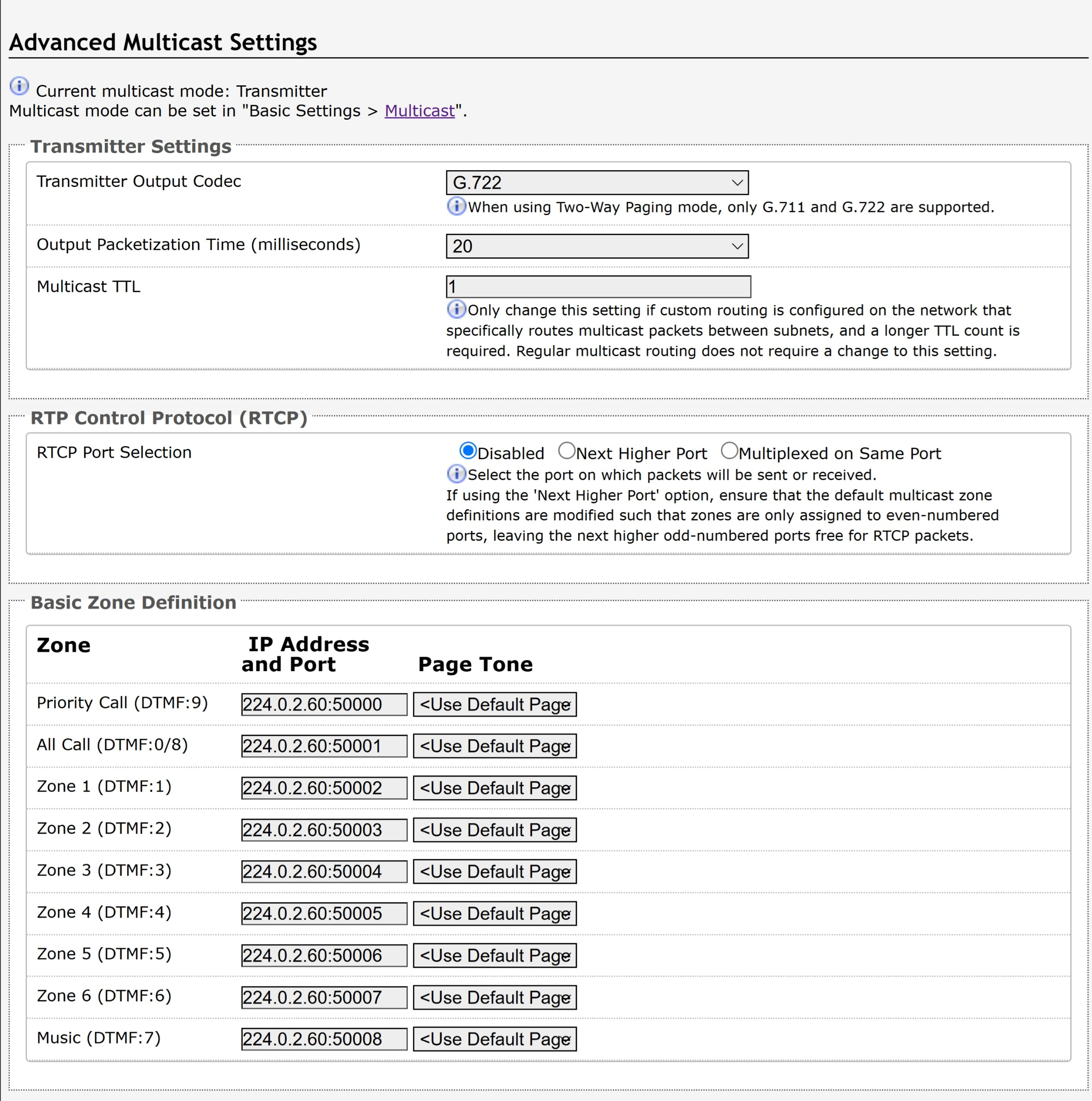
Transmitter Settings | |
Transmitter Output Codec | Select an audio encoding format for the Transmitter device to use when sending output to the Receivers. Supported formats include:
Only G.711 and G.722 are supported when using Two-Way Paging mode. |
Output Packetization Time (milliseconds) | Select the size of the audio packets the Transmitter sends to the Receivers from the dropdown menu. The default of 20 milliseconds is recommended unless a different value is specifically required for compatibility with other devices. |
Multicast TTL | Only change the multicast time to live (TTL) setting if custom routing is configured on the network that specifically routes multicast packets between subnets and a longer TTL count is required. This ensures packets are not bounced back and forth in a network indefinitely. When the TTL is reached, the router drops the packet. |
RTP Control Protocol (RTCP) | |
RTCP Port Selection | Select how a port will be chosen to send or receive RTCP packets.
|
Receiver Settings | |
Audio Sync | Available if the Multicast Mode is set to Receiver (Listener) in Basic Settings → Multicast. When using multicast with other third-party devices that have a delay in their audio path, the audio on the 8312 may be heard slightly earlier than on these other devices. Use this feature to add a small delay on the 8312 to synchronize with these other devices. |
Stream End Timeout | Time to wait after last received packet before confirming that a multicast stream has ended. Lower values allow faster switching between streams from different zones. |
Poly Receiver Tones | |
Poly Receiver Tones | Available if under Basic Settings → Multicast, the Multicast Mode is set to Receiver (Listener) and Multicast Type is set to Poly Group Page or Poly Push-to-Talk. A tone may be set for any of the 25 Poly Groups. If using an Algo device as a Multicast Transmitter, it is recommended to set the Receiver tones to None to avoid conflicts, as the Algo devices already multicast a tone by default. |
Appendix: Compliance and Safety
FCC Compliance Statement
This equipment has been tested and found to comply with the limits for a Class A digital device, pursuant to Part 15 of the FCC Rules. These limits are designed to provide reasonable protection against harmful interference when the equipment is operated in a commercial environment. This equipment generates, uses, and can radiate radio frequency energy, and if it is not installed and used in accordance with the instruction manual, it may cause harmful interference to radio communications. Operations of this equipment in a residential area is likely to cause harmful interference, in which case the user will be required to correct the interference at their own expense.
Product Warnings
Important Notice
This product is powered by a certified limited power source (LPS), Power over Ethernet (PoE); through CAT5 or CAT6 connection wiring to an IEEE 802.3at- or 802.3af-compliant network PoE switch. The product is intended for installation indoors. If the product is installed beyond the building perimeter or used in an inter-building application, the wiring connections must be protected against overvoltage/transient. Algo recommends that this product is installed by a qualified electrician.
If you are unable to understand the English language safety information then please contact Algo by email for assistance before attempting an installation support@algosolutions.com.
Emergency Communication
If used in an emergency communication application, the 8312 should be routinely tested. SNMP or ADMP supervision is recommended for assurance of proper operation. Contact Algo for other methods of operational assurance including the use of the integrated microphone for automated “sound to air” acoustic testing.