The Algo Device Management Platform (ADMP) is a cloud-based device management solution for managing, monitoring, and configuring Algo IP endpoints from any location. Service providers and system administrators can use ADMP to manage, monitor, and configure Algo IP endpoints across multiple locations and networks.
Note
Devices must have firmware version 5.2 or higher installed to be managed with ADMP. To access all the latest ADMP features, devices must be on the most recent firmware version available.
Setting up Your Account
To use ADMP, you must set up your account, tenant accounts, and licenses.
Account Tiers
There are three types of ADMP accounts:
Trial | A Trial account is a free 3-month account with access to 25 device licenses. To sign up for a trial account, fill out the form at https://www.algosolutions.com/admp-demo-license/. |
Pro | A Pro account uses device licenses that have been purchased or renewed. An Algo Support Team member sets up a Pro account after you’ve purchased device licenses. Device licenses may be purchased at https://www.algosolutions.com/product/admp/. |
Perpetual | A Perpetual account is available for Algo Authorized Integrators. To learn more about the Algo Authorized Integrator Program, visit https://www.algosolutions.com/integrator/. |
After you have signed up for a demo, purchased ADMP device licenses, or have become an Algo Authorized Integrator, an Algo Support Team member will reach out to set up account users.
User Permissions
You can access an ADMP account as either an Admin or a Viewer.
This table lists their different permissions.
Admin | Viewer |
An admin can access all pages and perform actions where applicable. | A viewer will only be able to view all pages. |
The Algo Support Team will be able to assist with adding new users, removing users, and updating user types upon request. There is no limit to the number of users you can have on an account. To add or remove users, the account owner should contact support@algosolutions.com for assistance.
Licenses
ADMP licenses are per device, not per person or account. Device licenses are purchased and renewed annually in bundles of 25. An account can have up to 10,000 licenses.
You may purchase additional device licenses through an Algo reseller, distributor, or on the Algo website here: https://www.algosolutions.com/product/admp/.
Multi-Tenant
To enable multi-tenancy, please reach out to the Algo support Team at support@algosolutions.com.
Multi-tenancy allows ADMP account holders to manage multiple deployments, or tenant accounts, from one main ADMP account. When multi-tenancy is in use, an ADMP account holder will log into ADMP and select the tenant account to view. From here, a user can monitor and manage devices connected to a tenant account.
Tenant Account Permissions
Permissions differ based on the type of tenant account.
The number of tenant accounts an ADMP account can have is unlimited.
To set up a new tenant, please contact the Algo Support Team at support@algosolutions.com.
The table below outlines the available permissions for each user type.
User Type | Permissions |
Administrator |
|
Additional Users |
|
Single Sign-On
To enable SSO, please contact the Algo support Team at support@algosolutions.com.
Single sign-on (SSO) for ADMP is available through a Microsoft account. SSO makes ADMP access seamless for designated users while improving account security. To provide SSO, ADMP uses Azure Active Directory (Azure AD), Microsoft’s enterprise cloud-based identity and access management (IAM) solution.
Note
A current limitation of SSO in ADMP is that one Azure AD can only be associated with one ADMP account, but not each tenant account. For example, a service provider who uses multiple tenant accounts for each of their customers can only have one Azure AD for their main account. Each customer, or tenant, cannot also use the same Azure AD separately.
However, a main account and tenant account may use separate Azure ADs, allowing SSO to be used for both a main account login or a single tenant login.
Setting up SSO
Before setting up SSO, it should be noted that users with SSO will no longer be able to log in using a password. Only one login option can be applied to an account.
To set up SSO:
Sign in to the Microsoft Entra admin center as at least a Cloud Application Administrator.
Go to Users and select + New user → Create new user.
.png)
Configure the new user information and then select Review + create.
.png)
Repeat this process to add more users.
Go to Enterprise apps.
Click All applications, then select + New application.
.png)
Click + Create your own application.
.png)
Configure the following, then select Create.
.png)
Enter your application name.
Select Integrate any other application you don't find in the gallery (Non-gallery).
Select Set up single sign on.
.png)
Select SAML as the single sign-on method.
.png)
Select Edit for Basic SAML Configuration.
.png)
Configure the basic SAML settings and then select Save.
Select Add Identifier and enter
urn:amazon:cognito:sp:us-east-1_29zRSC27FSelect Add reply URL and enter:
https://admp.auth.us-east-1.amazoncognito.com/saml2/idpresponseEnter Sign on URL:
https://dashboard.cloud.algosolutions.com
.png)
Go back to Single sign-on and select the Copy icon
.png) to obtain the App Federation Metadata URL.
to obtain the App Federation Metadata URL..png)
Provide the Algo Support Team with the App Federation Metadata URL from the previous step.
Select Edit under Attributes & Claims.
.png)
Select Unique User Identifier.
.png)
Change the Source to Transformation.
.png)
Set the transformation, then select Add.
.png)
Transformation: Set as
ToLowercase().Parameter 1: Set as Attribute.
Attribute name: Set as
user.userprincipalname
Select Add.
Using SSO
When SSO is set up, you can access ADMP via https://dashboard.cloud.algosolutions.com/sso. The login page will look slightly different from the regular ADMP login page.
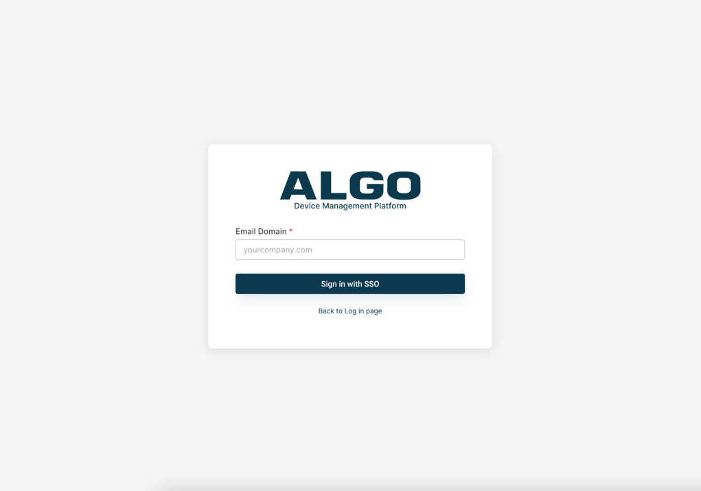
To log in using SSO:
Enter the domain of your email.
For example, instead of support@algosolutions.com, you would enter algosolutions.com.
You will be redirected to a Microsoft login if you are not already logged in to your Microsoft account.
Once you enter your credentials, you’ll be redirected back to ADMP to access your account.
Getting Started
Once your ADMP account is set up, you will receive login credentials via email.
The email will be sent from no-reply@cloud.algosolutions.com and will contain your username and password.
.png)
Logging in to ADMP
You must log in to ADMP to manage or monitor your devices.
To log in to ADMP:
Open a web browser and go to: https://dashboard.cloud.algosolutions.com/.
Enter your user name and password, and then select Sign in.
On your first login, follow the on-screen instructions to change your password.
Viewing Your Tenant Accounts
You can view detailed information about available tenant accounts and switch between different accounts.
To view your ADMP tenant accounts:
Select the Enter icon
 on the right of the desired account panel.
.png)
To go back to the Account Manager:
Select Back to Account List on the top right of the page.
.png)
Obtaining Your ADMP Account ID
Each tenant account has a unique ID. You must provide the account ID when:
Connecting your device to ADMP.
Contacting Algo support to request ADMP-related assistance.
To obtain the ADMP account ID:
Select your Account icon
 to view the account info.
To copy the Account ID, select the Copy icon
 .
.
Connecting Algo IP Devices to ADMP
To monitor your devices in ADMP, you must first connect them to your account. You can do this manually using the web interface for each endpoint or via zero-touch provisioning.
Adding Algo Devices Manually to ADMP
To manually connect an Algo IP endpoint, you must enable ADMP Cloud Monitoring from the device web interface.
.png)
To enable ADMP Cloud Monitoring for an Algo device:
Go to Advanced Settings → Admin.
Under ADMP Cloud Monitoring, set Enable ADMP Cloud Monitoring to Enabled.
Enter your ADMP account ID in Account ID.
To allow ADMP to query and display settings stored on the device, select Allow Configuration File Sync.
Specify how often ADMP should check the status of your device in Heartbeat Interval.
Select Save.
After a few minutes, your Algo device will be connected to ADMP.
On the Status tab of the device web interface, you should see ADMP Cloud Monitoring set to Connected.
Your device will also now be listed on the Devices page of ADMP.
Using ZTP to Bulk Add Devices to ADMP
In large-scale deployments, Zero Touch Provisioning (ZTP) can automatically bulk add devices to the ADMP, eliminating the need to manually enable ADMP Cloud Monitoring on each unit.
For more information, see Zero-Touch Provisioning (ZTP)
Using Search and Filters
The search and filter functions are available on many pages of the system.
Key features include:
Partial search
You can search using partial tag text, MAC address, IP address, product model, firmware version, connection status, and more.
Logical operators
When selecting multiple tags, you can use the logical operators AND and OR to create more advanced search conditions.
.png)
Dashboard
When you log into your ADMP account, the Dashboard page appears first.
It provides a summary of your connected Algo IP endpoints.
Overview
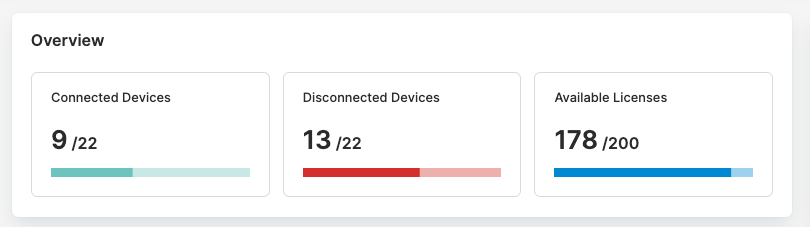
The Overview section displays a quick summary of the count of your devices and licenses.
Item | Description | ||
|---|---|---|---|
Connected Devices | The number of connected devices out of the total detected devices, including those connected and disconnected. | ||
Disconnected Devices | The number of disconnected devices out of the total detected devices, including those connected and disconnected. | ||
Available Licenses | The remaining device licenses you have available to manage additional Algo IP endpoints from ADMP. |
Upgradable Devices
Devices listed here have new firmware available. You can install the latest firmware directly through ADMP.
.png)
Item | Description |
|---|---|
Device ID | The MAC address of your device. |
Device Name | The product name of your device. |
Product ID | The SKU number of your device. |
Current Firmware | The firmware version the device is currently using. |
To upgrade device firmware:
On the Dashboard page, go to the Upgradable Devices section.
Select Upgrade All.
Select desired devices.
Check the Latest Firmware to ensure this is the firmware version you want.
Select Upgrade.
The selected devices disappear from the Upgradable Devices section.
On the Devices page, their Status changes to Upgrading. Upon successful upgrade, the Status changes to Connected.
Product List
The Product List shows all device models connected to ADMP in your deployment and the number of devices for each model.
.png)
Entry | Description |
|---|---|
Product ID | The SKU number of your device. |
Product Name | The product name of your device. |
Quantity | The number of deployed devices of the listed product. |
Connected vs. Disconnected
A pie chart that represents the connected and disconnected devices.
The Connected status indicates that the device has ADMP Cloud Monitoring enabled and is currently online.
The Disconnected status indicates that the device is offline, has ADMP Cloud Monitoring disabled, or both.
.png)
Notifications
The Notifications section on the Dashboard displays essential updates such as system outages, upcoming changes, and new ADMP features.
Note
Check this section regularly because these notifications are not sent by email.
.png)
Managing Devices
Use the Devices page to manage and maintain all connected devices.
You can delete devices, add tags to a device, search, or filter devices.
You can view three lists: All, Connected, and Disconnected.
Entry | Description |
|---|---|
Device ID | Each Algo device has a unique ID. This ID is the same as the device MAC address. |
Local IP | The IP address of each device used to access the device's web interface. If you are using ADMP on a different network than the one the device is using, you may not be able to reach this IP address. |
Name | The device name or hostname registered in the device web interface. |
Product | The SKU number of your device. |
Firmware | The firmware version the device is currently using. |
Tags | Customizable tags used to easily group devices together based on location, use, or any other preference. |
Status | Each device will show its status as Connected or Disconnected. When an action is in progress, the status will appear as Rebooting, Upgrading, Configuring, Setting, Deleting, Downloading, or Trying. |
Viewing Device Status Information
The Device Status window provides detailed information about the selected device and quick access to common actions. The available status information and actions may vary depending on the device model, configuration, and connection status.
.png)
Related Links:
To view a device status:
Select More
.png) → Device Status.
→ Device Status..png)
Using Tags
You can add tags to devices to include additional device information, such as location, function, or department.
For example, tagging a device with “Hallway” makes it easier to locate the device from the device list.
You can:
Create, assign, and remove tags for a device on the Devices page.
Modify or delete a tag name or color on the Configure page.
Note
Tags are not case-sensitive.
.png)
Adding Tags to Devices
Each device can have up to 8 tags. You can create and use up to 100 tags across all devices.
Note
You can add tags from several places:
From the Devices page
From the Configure page
Tags created from the Devices page have the default color blue. To create tags with other colors, create tags from the Configure page.
To add a tag to a device:
Go to the Devices page.
Select the desired devices.
Select Add Tag.
Do one of the following:
Select an existing tag.
Type a new tag and click + Create Tag to create and apply a new tag.
.png)
Selected tags are applied to the chosen devices, unless the device already has eight tags.
Removing Tags from a Device
You can remove tags from a device.
.png)
To remove a tag from a device:
Go to the Devices page.
In the device list, select the Delete icon
 on the desired tag.
Applying Actions to Devices
You can manage online devices on the Devices page. For example, upgrading or rebooting devices.
You can apply an action in one of the following ways:
Applying an action from the Actions drop-down list
You can apply an action to multiple devices at a time.
.png)
Applying an action from the More
 menu of a device
You can apply actions to individual devices.
Note
Some device-specific actions are only available through the More menu
. (1) (1).png)
Note
All actions except Delete and Add tag are available only when the device status is Connected.
Testing Devices
You can run a test to verify that a device is working properly.
Test behavior varies depending on the device type.
When a test is performed:
IP Speakers, IP Displays, Intercoms: The default tone plays.
Paging Adapters: A tone plays if the device is connected to an audio device.
Visual Alerters: The strobe light flashes.
To test devices:
Go to the Devices page.
Select the Connected tab.
Do one of the following:
To test a single device, select it and then select Test from the More
menu or the Actions drop-down list.To test multiple devices, select the devices and then select Test from the Actions drop-down list.
Rebooting Devices
You can reboot a device from ADMP. This will not reset the device’s settings.
To reboot devices:
Go to the Devices page.
Select the Connected tab.
Do one of the following:
To reboot a single device, select it and then select Reboot from the More
menu, or from the Actions drop-down list.To test multiple devices, select the devices and then select Reboot from the Actions drop-down list.
Upgrading Devices to a Specified Firmware Version
You can upgrade device firmware to a specified version.
You can also bulk upgrade devices to a newer firmware version for the same product model.
Note
You can not downgrade the firmware.
To upgrade devices to a specified firmware version:
Go to the Devices page.
Select the Connected tab.
Do one of the following:
To upgrade a single device, select it and then choose Upgrade from the More
menu, or from the Actions drop-down list.To upgrade multiple devices of the same product model, select the devices and then choose Upgrade from the Actions drop-down list.
Enter the firmware file path URL.
The firmware version must be higher than the current one. Otherwise, the upgrade action will fail.
Select Upgrade.
During the upgrade, the selected devices disappear from the Connected tab.
On the Devices → All tab, page, their Status changes to Upgrading. After a successful upgrade, the new firmware version displays.
Upgrading Devices to the Latest Firmware
You can upgrade selected devices to the latest firmware from the Algo firmware server.
You can also bulk upgrade devices to the latest firmware version for the same model.
To upgrade a device to the latest firmware:
Go to the Devices page.
Select the Connected tab.
Do one of the following:
To upgrade a single device, select it and then choose Upgrade Latest from the More
menu, or from the Actions drop-down list.To upgrade multiple devices, select the devices and then select Upgrade Latest from the Actions drop-down list.
Select Upgrade.
The selected devices disappear from the Connected tab.
On the Devices → All tab, page, their Status changes to Upgrading . After a successful upgrade, the firmware version is updated automatically.
Pushing Configurations to Devices
You can push configurations onto selected devices.
When processing a configuration file, the system applies changes as follows:
Valid parameters with valid values: Values are applied to the applicable devices.
Valid parameters with invalid values: No changes are made.
Invalid parameters: Parameters remain in the configuration file but do not affect device settings.
Parameters not included in the file: Existing device settings remain unchanged.
Note
Partial configuration files are best for bulk configuration updates.
If you plan to use multicast, you should not push the same configuration file to all devices. Your sender and receiver devices will require different configurations.
Creating a Configuration File
You can create a custom configuration file and upload it to ADMP.
For IP Displays, you can also use Mass Configure to create configuration files.
Related Links:
To create a configuration file:
Do one of the following:
Create a plain text file and add the parameters you want to update.
Download the configuration file of a device and change the desired parameter settings.
Save the file as a
.txtfile.Go to File Manager → Files→ Configs.
Drag and drop your
.txtfile into the Configs folder.Now the file is available in the Select a configuration file drop-down list when you select Push Config for a device.
Related Links:
Pushing Configurations to a Device
You can push a configuration file to an individual device or multiple devices simultaneously.
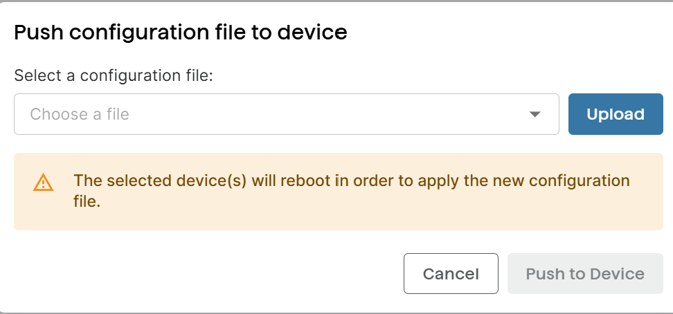
To push configurations to a device:
Go to the Devices page.
Select the Connected tab.
Do one of the following:
To push configurations to a single device, select it and then select Push Config from the More
menu, or from the Actions drop-down list.To push configurations to multiple devices, select the devices and then select Push Config from the Actions drop-down list.
Do one of the following:
Select a configuration file from the drop-down list
Select Upload to use a configuration file from your computer.
Select Push to Device.
The selected devices disappear from the Connected tab.
On the Devices → All tab, page, their Status changes to Configuring during the setting update.
The selected devices will reboot to apply the configuration changes.
Setting Device Volume
You can set the ring and page volumes for speakers and paging adapters.
The Ring Volume and Page Volume can be set from -5 to 10. Each level from –5 to 10 increases the volume by 3 dB. The lowest setting (–5) is 45 dB below the maximum setting (10).
To set device ring and paging volume:
Go to the Devices page.
Select the Connected tab.
Do one of the following:
To change the volume for a single device, select it and then select Set Volume from the More
menu, or from the Actions drop-down list.To change the volume for multiple devices, select the devices and then select Set Volume from the Actions drop-down list.
Set the Ring Volume and Page Volume.
Select Set Volume.
Removing Devices
You can remove devices from ADMP to stop monitoring them. This doesn’t erase device configuration.
Note
Deleting a connected device causes it to reboot if the device firmware is lower than version 5.5.
To delete devices from ADMP:
Go to the Devices page.
Do one of the following:
To delete a single device, select it and then select Delete from the More
menu, or from the Actions drop-down list.To delete multiple devices, select the devices and then choose Delete from the Actions drop-down list.
Select Delete to confirm the action.
Devices with a firmware version lower than 5.5 will reboot.
In the device web interface, ADMP Cloud Monitoring now shows as Disabled.
Downloading System Log
You can download system logs to assist with troubleshooting, monitoring, or system auditing.
When downloaded, a .txt file containing your device’s events and messages is saved to your computer’s default download folder.
For Windows users, the file is typically saved to: C:\Users\<USERNAME>\Downloads.
The file name follows this format: <device-mac>-syslog.txt.
To download the system log:
Go to the Devices page.
Select the Connected tab.
Select Download Syslog from the More
menu of the desired device.
Downloading Device Configuration File
You can download the device configuration file to check the configurations or to customize them.
When downloaded, a .txt file containing your device’s system configurations is saved to your computer’s default download folder.
For Windows users, the file is typically saved to: C:\Users\<USERNAME>\Downloads.
The file name follows this format: <device-mac>-config.txt.
To download the system configuration file:
Go to the Devices page.
Select the Connected tab.
Select Download Config from the More
menu of the desired device.
Accessory Fault Detection
If a connection issue is detected, devices that support accessory supervision will show a fault detection icon on the Devices page.
For example, a fault will appear if a satellite speaker disconnects from its main speaker or a call button with a paging adapter doesn't function properly.
You can also enable email notifications for device faults in Settings → Notification Settings.
.png)
Applicable devices include:
IP speakers that support satellite speakers:
Algo 8196 IP PoE+ Horn Speaker
Algo 8197 IP PoE+ Weather-Hardened Horn Speaker
Algo 8198 IP PoE+ Ceiling Speaker
Algo 8199 IP PoE+ Surface Mount Speaker
Call switches:
Algo 1202 Call Button
Algo 1203 Call Switch
Algo 1204 Volume Control Switch
Algo 1211 Single Button
Algo 1212 Dual Button
Other devices that support relay with supervision mode
Related Links:
Using Remote Device UI
You can access and configure some Algo devices directly from ADMP without being on the same network as the device.
This feature simplifies multi-site management, supports remote troubleshooting, and eliminates the need for VPNs or local network access in device management.
Changes made in Remote Device UI are applied directly to the device.
Note
Before configuring device settings using the Remote Device UI, make sure your device is running the latest firmware.
Devices that Support Remote Device UI
The Remote Device UI is currently only available for the following devices.
IP Speakers
IP Displays
| Paging Adapters
Intercoms
Visual Alerters
IP Clocks
|
Prerequisites for Using the Remote Device UI Feature
To use Remote Device UI in ADMP, ensure the following requirements are met:
The device supports Remote Device UI.
The device is running firmware version 5.5_alpha15 or higher.
The device has a Connected status in ADMP.
Allow Configuration File Sync is enabled in the device’s web interface (under Advanced Settings → Admin → ADMP Cloud Monitoring).
Accessing a Remote Device Web Interface
When Remote Device UI is available, a gear icon appears next to the device ID in the ADMP Devices tab.
Note
You can access the Remote Device UI only when the device is connected to ADMP. If it's not connected, the Remote Device UI icon
.png)
Changing Device Settings from Remote Device UI
You can change device settings using the Remote Device UI feature.
.png)
To change device settings from the Remote Device UI:
Go to the Devices page.
Select the Connected tab.
Select the Remote Device UI
.png) icon next to the desired device.
icon next to the desired device.Make desired configuration changes, and then select Push to Device.
This operation updates the device configurations and closes the Remote Device UI.
To exit the Remote Device UI, select the Exit
.png) icon on the top right of the Remote Device UI screen.
icon on the top right of the Remote Device UI screen.
Saving Configuration Changes as Draft
If you attempt to exit the Remote device UI without pushing the configuration to the device, you can save configuration changes as a draft.
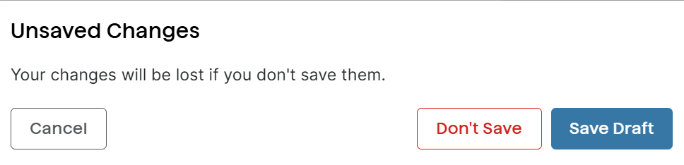
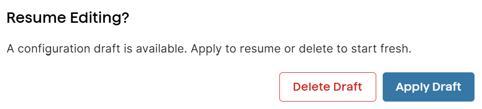
If you select Save Draft, the next time you open the Remote device UI, you are prompted to resume editing or delete the draft.
Configuring Tags and Mass Confi
You can add or delete device tags or disable devices from mass configuration.
You can also add or remove tags from the Devices page. To customize tag colors, create tags from the Configure page.
 (1).png)
Managing Tags
Tags help describe devices in more detail and allow you to filter them by tag text.
You can create or delete tags.
You can apply up to eight tags to a device.
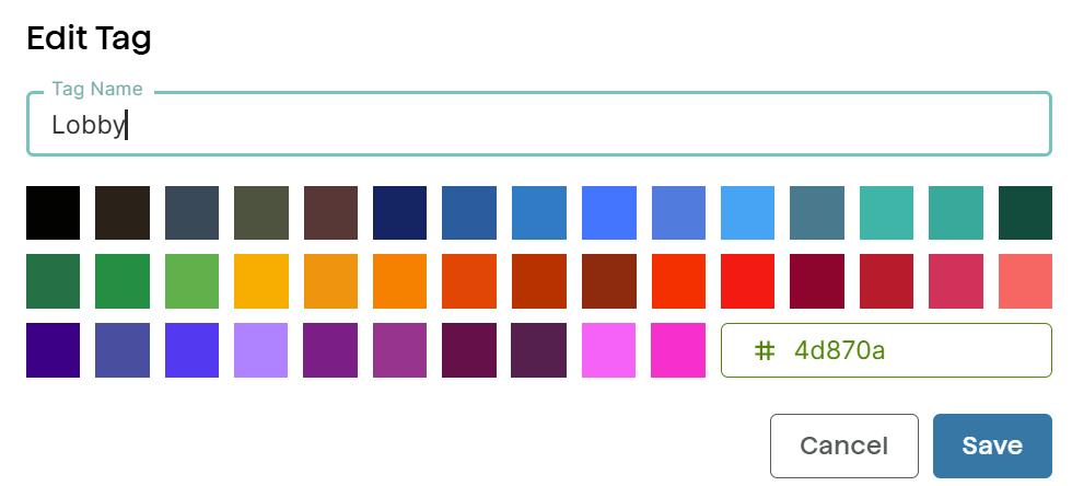
To create new tags:
Go to Configure.
Select + Add Tag.
Enter a tag name.
Select a tag color. To customize the color, enter a Hex color code, such as #6CC4.
Select Confirm.
To edit an existing tag
Go to Configure.
Select an existing tag.
Change the tag name or tag color. To customize the color, enter a Hex color code, such as #6CC4.
Select Confirm.
To delete a tag:
Go to Configure.
In the Tags section, select the Delete icon
on the desired tag.When asked to confirm the action, select Delete.
Note
If you try to delete a tag that is currently in use, the system will prompt you and display the devices affected. Deleting the tag will also automatically remove it from all associated devices.
Excluding Devices From Mass Configuration
You can exclude devices when a mass configuration is initiated. Any devices added have a Lock icon .png) on the left side of the device’s row on the Devices page.
on the left side of the device’s row on the Devices page.
Note
Devices that are disabled from mass configuration can still be configured individually on the Devices page by using the More icon on the right side of the device’s row.
To exclude devices from mass configuration:
Go to Configure.
In the Disabled Devices for Mass Config section, select + Add Devices.
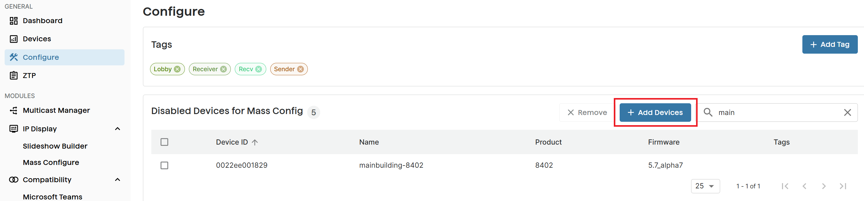
Select the desired devices and then select Disable.
In the Devices page, a Lock icon
appears on the left of the device entry.(1) (1).png)
Zero-Touch Provisioning (ZTP)
The Zero Touch Provisioning (ZTP) service automatically directs devices to a server during startup to download their configuration files. This makes deploying many devices faster and easier in large settings like schools, factories, or businesses.
Note
All Algo IP endpoints shipped after November 2022 support Zero Touch Provisioning (ZTP). Devices shipped before November 2022 do not have ZTP enabled by default, even after a firmware upgrade. To enable ZTP on these devices, please contact Algo Support.
ZTP is enabled on Algo devices by default. However, the setting is disabled as soon as you manually configure the device. ZTP remains active only during the initial installation or after a factory reset.
Security
ZTP is secured using TLS mutual authentication with certificates. Each Algo IP endpoint has a unique device certificate installed at the factory, tied to its MAC address.
When the device boots up, it automatically connects to Algo’s ZTP server (ztp.algosolutions.com) and establishes a secure TLS connection using its device certificate. This ensures all data transferred is fully encrypted.
Once a MAC address is registered in the ZTP configuration, it is locked to that account and cannot be claimed by another—preventing accidental or malicious hijacking. However, if the MAC address is removed from the configuration, it becomes available to be claimed by another account.
Using ZTP Service
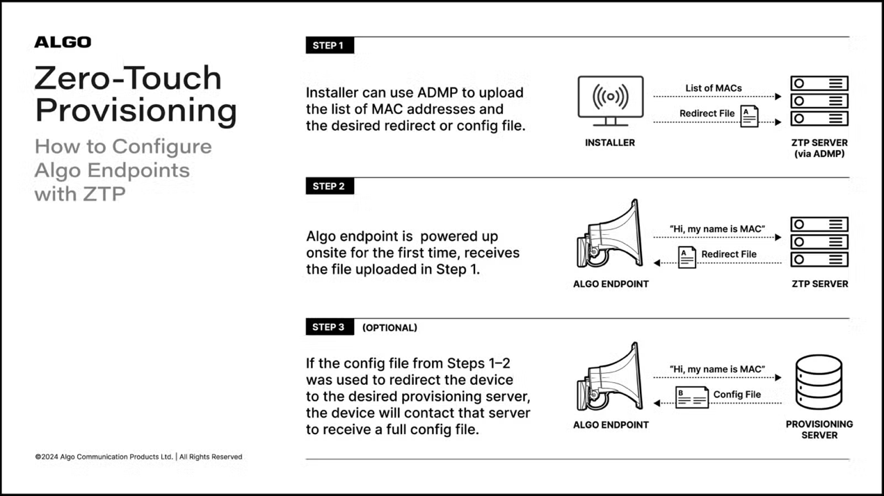
Follow these steps to use the ZTP service:
Obtain ZTP service if you currently do not have it.
If you don’t currently have ZTP service, contact Algo Support to request access.
Upload configuration files
Upload a list of device MAC addresses and a redirect or configuration file to the ZTP server (ztp.algosolutions.com).
Map configuration files to devices
After the mapping is done, when the Algo endpoint is powered on for the first time, it automatically connects to the ZTP server and retrieves the redirect or configuration file associated with its MAC address.
Obtaining ZTP Service
Algo’s ZTP service is free and can be accessed through ADMP. While full ADMP access requires a license, no license is needed to use ZTP.
You can request a ZTP-only ADMP account free of charge. A ZTP-only account holder can only configure mass provisioning for devices, but they can not manage devices. However, you can add a device management license to your ZTP-only account at any time.
Devices shipped before November 2022 do not have ZTP enabled by default, even after a firmware upgrade. To enable ZTP on these devices, please contact Algo Support.
To obtain a ZTP-only account:
Submit a ZTP request form.
Creating Configuration Files
It is recommended that you download an existing device configuration file and use it when creating a custom one.
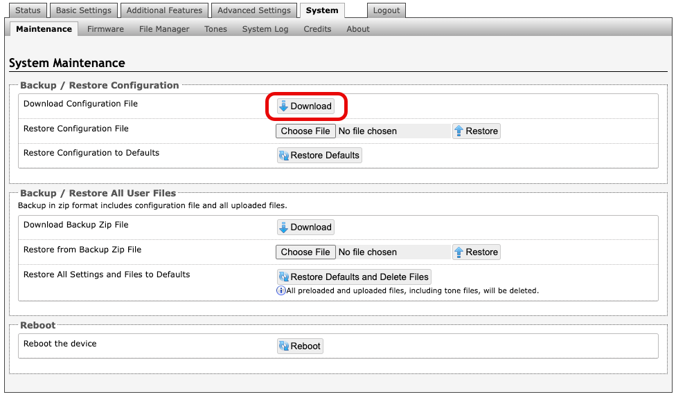
To download a configuration file from the device web interface:
Go to System → Maintenance.
Select Download Configuration File from the Backup / Restore Configuration section.
Configuration File Requirements
Observe the following requirements to create your configuration files for use with ZTP:
It must be in the format .txt.
It must be a valid Algo configuration file. Any settings not specified in the file will retain their default factory values.
To redirect your devices to a provisioning server, your configuration file should contain:
prov.server.method = static
prov.server.static = https://some-local-server
prov.sync.endtime = 03:00:00
prov.sync.frequency = daily
prov.sync.time = 02:00:00
prov.use = 1
prov.i = 1
To enable ADMP cloud monitoring on your device, your configuration file must contain:
iot.mqtt.ka = 30
iot.tenant = [ADMP account ID]
iot.use = 1
iot.sync.conf = 1
Where:
iot.useEnable the device to connect to ADMP.iot.tenant: Specify the ADMP account that the device wishes to connect to.iot.syn.conf: Allow the device to send its configurations to ADMP..
Note
Algo’s ZTP service is primarily meant to redirect traffic to your provisioning server. While it will accept files containing additional settings, such as SIP parameters, it is not intended for this purpose.
Related Links:
Uploading Configuration Files
You must upload the desired configuration files and associate them with device Mac addresses.
To upload a new configuration file:
Select ZTP and then select Configuration Files
 .
..png)
Drag and drop your configuration file into the window or browse and select your files.
Select Upload.
To view the configuration file content, select the View icon
 on the file entry.
Mapping Devices with Configuration Files
You must map devices to their configuration files using their MAC addresses. When using ZTP, once a MAC address has been claimed by an ADMP account, it cannot be claimed by another. If the MAC address is removed from ADMP, it may be claimed by another account.
.png)
Item | Description |
|---|---|
MAC Address | The MAC address of an added device. A device MAC address can be found on the Status → Device Status page of the device web interface. |
Configuration File | The selected configuration file is to be applied to the device using ZTP. |
Last Contacted | The most recent date the device contacted ADMP. |
Last Modified | The most recent date the device mapping was modified. |
Provisioned | Whether or not a device has been successfully provisioned. If part of your provisioning includes connecting the device to ADMP, you will be able to use the primary Device and Configure pages of ADMP for additional configuration. |
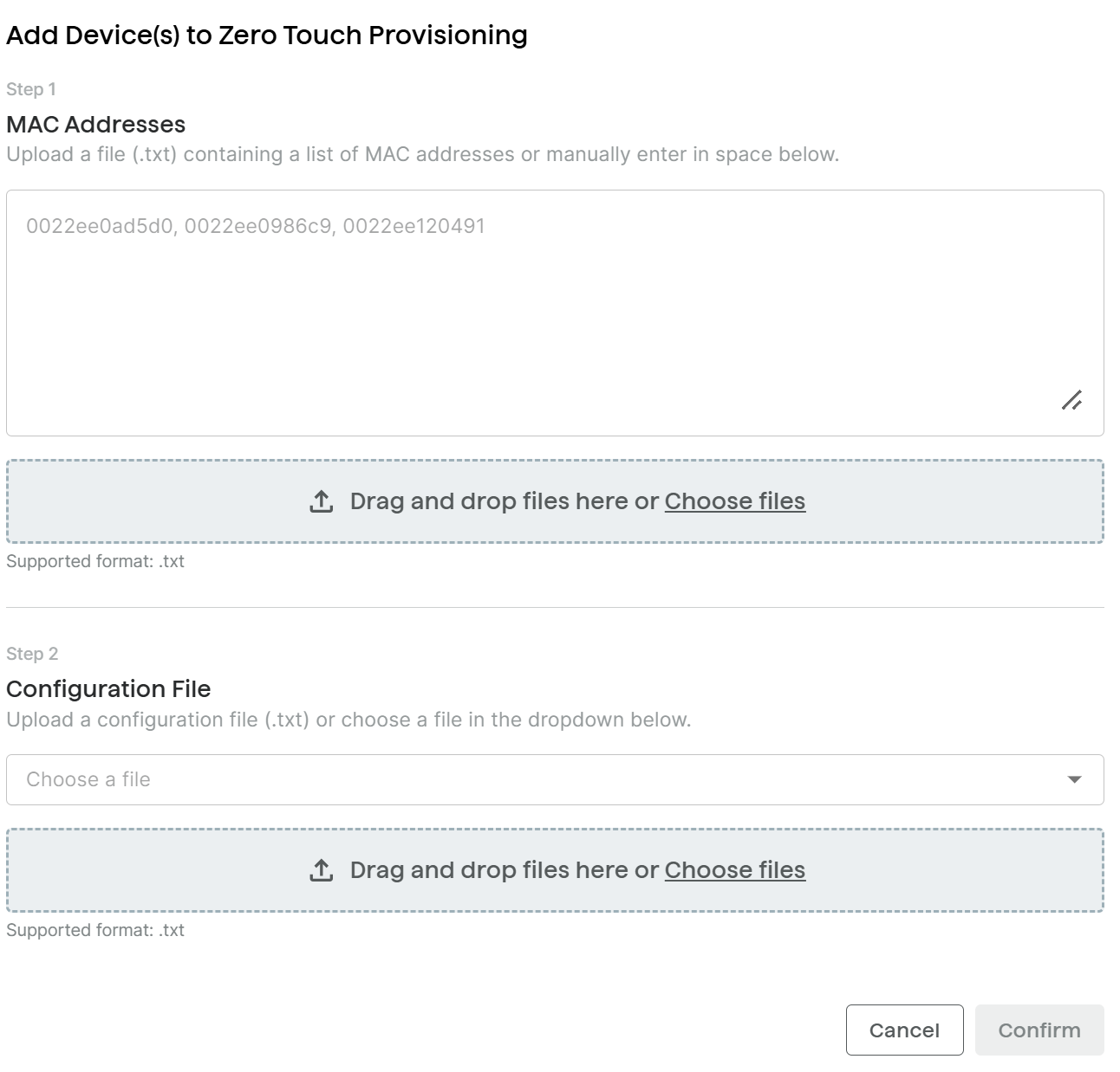
To add devices for ZTP provisioning:
Select ZTP.
Click + Add Devices.
Do one of the following:
Upload a .txt file containing a list of MAC addresses for your devices.
You can use a comma, tab, or line break to separate MAC addresses in your .txt file.
Enter the list of MAC addresses directly into the window.
You can use a comma, tab, or line break to separate MAC addresses.
Select a configuration file from the drop-down menu, or upload a new one.
Select Confirm.
When a device with a matching MAC address powers on for the first time, it connects to the ZTP server, retrieves its configuration, and automatically applies the settings.
Modifying the Device Mapping
You can modify the mapping if you make an error and want to change the configuration file.
This must be done before the device boots up for the first time. Otherwise, the change will not take effect.
To modify the device mapping:
Select ZTP.
Do one of the following:
To modify multiple mappings at a time, select all devices and click Modify.
To modify a single device, select the More icon
.png) on the device entry and then select Modify.
on the device entry and then select Modify.
Select a new configuration file.
Select Confirm.
System Log
The system log records user actions and changes made in ADMP. This makes it easy to audit or troubleshoot your ADMP account. This data is stored in ADMP for up to a year.
.png)
Recorded device details include:
|
|
Additional ADMP details include:
|
|
To audit and troubleshoot devices, the system log provides a list of ADMP user actions related to device configuration for up to a year.
Actions recorded in the System Log include:
|
|
It should be noted that:
All ADMP account users will have access to the System Log
Actions that have failed will not be reported in the System Log
Details at the specific device level will not be reported (ex. accessory fault detection)
Exporting System Log File
You can download the system logs to assist with system auditing or troubleshooting.
To export the system log file:
Go to System Log.
Select Export at the top right of the screen.
The system log is Exported as a .csv file and saved to your computer's default download folder.
Backing Up Device Configurations
If your device is on firmware 5.3 or later, you can download the device configuration file and data.
This helps to assist device troubleshooting or restore device configurations in case of device failure.
Note
Backup of a device's configuration file may fail if the device is busy or disconnected.
Your device must be on firmware 5.3 or later.
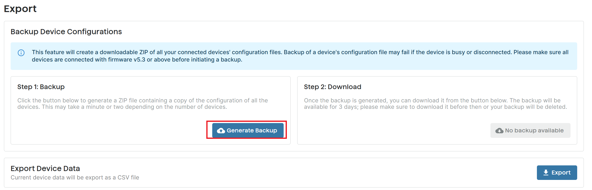
Clicking Generate Backup allows you to download a ZIP of all configuration files used on connected devices.
To download the device configuration:
Go to Export.
Under Step 1: Backup, select Generate Backup.
This generates a ZIP file containing a copy of the configuration of all the devices. Depending on the number of devices, this may take a minute or two.
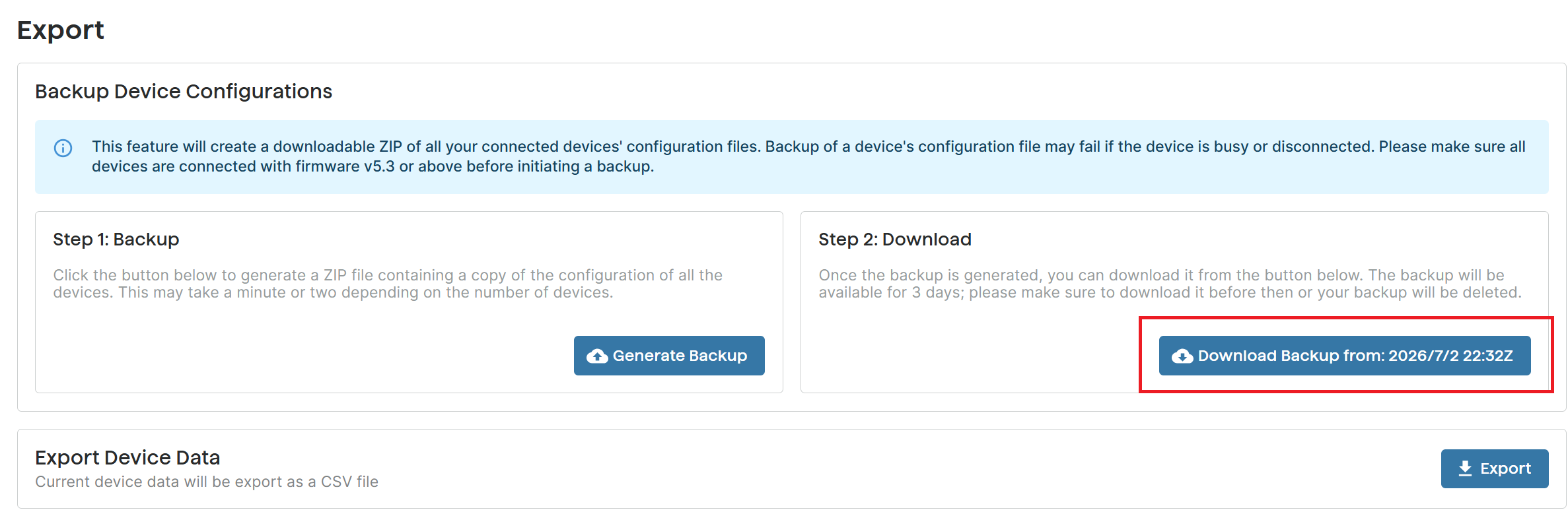
Select Download Backup From: [Date] when this option is available.
This downloads the configuration files as ADMP device Export.zip to your computer’s default download folder.
Note
Download the configuration files in time. The Download Backup From: [Date] option will be available for three days.
When you click download, a ZIP file will be downloaded. After you unzip the file, you’ll find various .txt files for your products as well as a file called ADMP device export report.csv.
.png)
Open ADMP device export report.csv to review the data. This report will include a list of devices and the number of successful, failed, and skipped devices.
Exporting Device Data
You can export the list of devices monitored by ADMP, along with their basic information, such as MAC address, connection status, and tags.
This is helpful for internal auditing, especially if this data is Exported on a regular basis.
The following device data is Exported:
Item | Description |
|---|---|
Device ID | The MAC address of your device. |
Status | Device connection status to ADMP. |
Device Name | The product name of your device. |
Product ID | The SKU number of your device. |
Firmware Version | The firmware version the device is currently using. |
Tags | Tags added to the device. |
To export device data:
Go to Export.
Select Export in the Export Device Data section.
The device data is exported as a .csv file and saved to your computer’s default download folder.
File Manager
You can use the File Manager to upload configuration files, images for creating slides, or tones.
You can push configurations to connected devices, or synchronize icons, images to applicable devices later.
You can also manage files, such as previewing, editing, or deleting.
Note
Your file names can only contain alphanumeric characters, dashes, or underscores.
.png)
Note
If you uploaded configuration files via the Configure page in earlier versions of ADMP, you can still access them in File Manager.
There is no need to re-upload the files.
Related Links:
File Formats
When uploading files to the File Manager, refer to this table for supported file formats and requirements.
Folder | Supported Format | Note |
|---|---|---|
certs | CRT | |
icons | BMP, CUR, GIF, ICNS, ICO, JPEG, JPG, PBM, PGM, PNG, PPM, SVG, SVGZ, TGA, TIF, TIFF, WBMP, WEBP, XBM, XPM | Recommended file size: 1200 × 130 pixels. Icons are scaled to fit the icon frame in the selected slide template while preserving their aspect ratio. |
images | BMP, CUR, GIF, ICNS, ICO, JPEG, JPG, PBM, PGM, PNG, PPM, SVG, SVGZ, TGA, TIF, TIFF, WBMP, WEBP, XBM, XPM |
|
tones | 8SVX, AIF, AIFC, AIFF, AIFFC, AL, AMB, AMR-NB, AMR-WB, ANB, AU, AVR, AWB, CAF, CDDA, CDR, CVS, CVSD, CVU, DAT, DVMS, F32, F4, F64, F8, FAP, FLAC, FSSD, GSM, GSRT, HCOM, HTK, IMA, IRCAM, LA, LPC, LPC10, LU, MAT, MAT4, MAT5, MAUD, MP2, MP3, NIST, OGG, PAF, PRC, PVF, RAW, S1, S16, S2, S24, S3, S32, S4, S8, SB, SD2, SDS, SF, SL, SLN, SMP, SND, SNDFILE, SNDR, SNDT, SOU, SOX, SPH, SW, TXW, U1, U16, U2, U24, U3, U32, U4, U8, UB, UL, UW, VMS, VOC, VORBIS, VOX, W64, WAV, WAVPCM, WV, WVE, XA, XI | Audio files must be in the following format:
|
Configs Folder
This folder contains device configuration files. You can upload, view, edit, download, or delete configuration files.
The file can be named anything you would like. However, the following is necessary for a configuration file to be used in ADMP:
It must be in the format .txt
It must be a valid Algo configuration file or a partial Algo configuration file.
A partial configuration file is a provisioning file that contains only selected settings rather than the full configuration of a device.
Partial configuration is recommended when you want to reconfigure some but not all settings across several devices.
Tones Folder
Custom audio files may be uploaded to play notifications. Audio files should be stored in the tones directory.
Existing files may be modified by downloading the original file, making the desired changes, then uploading the updated file with a different name.
Icons Folder
The Icons folder stores icons that you can use in slide headers.
Images Folder
Upload images to use in your slides.
Managing Files in File Manager
You can upload, view, or manage device configuration files, images, or tones in the File Manager.
.png)
Note
Available operations vary depending on the file type.
For example, you can not edit a tone file or delete system default images and tones.
To upload a new file:
Go to File Manager.
Select a target folder:
Configs: Select this folder to upload device configuration files.
Images: Select this folder to upload images to be used with your IP speakers.
Tones: Select this folder to upload audio files to be used with various events.
Do one of the following:
Select Upload and select files from your computer.
Drag and drop files into the folder.
To preview a file:
Go to File Manager.
Select a target folder.
Right-click a file and then select Preview.
To rename a file:
Go to File Manager.
Select a target folder.
Right-click a file and then select Rename.
Enter the new name.
To delete a file:
Go to File Manager.
Select a target folder.
Right-click a file and then select Delete.
To edit a file:
Go to File Manager.
Select a target folder.
Right-click a file and then select Edit.
Multicast Manager
The Multicast Manager simplifies multicast configuration across zones and devices. You can bulk add, remove, or configure multicast devices, ensuring consistent zone configurations across all devices.
Note
The Multicast Manager supports regular multicast only (RTP multicast). For multicast configurations involving Poly devices, use the device’s web interface instead.
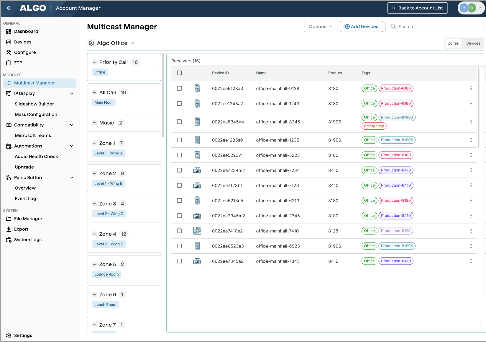
It provides an intuitive interface to view devices by transmitter, receiver, or multicast zone.
Zone View
Device View
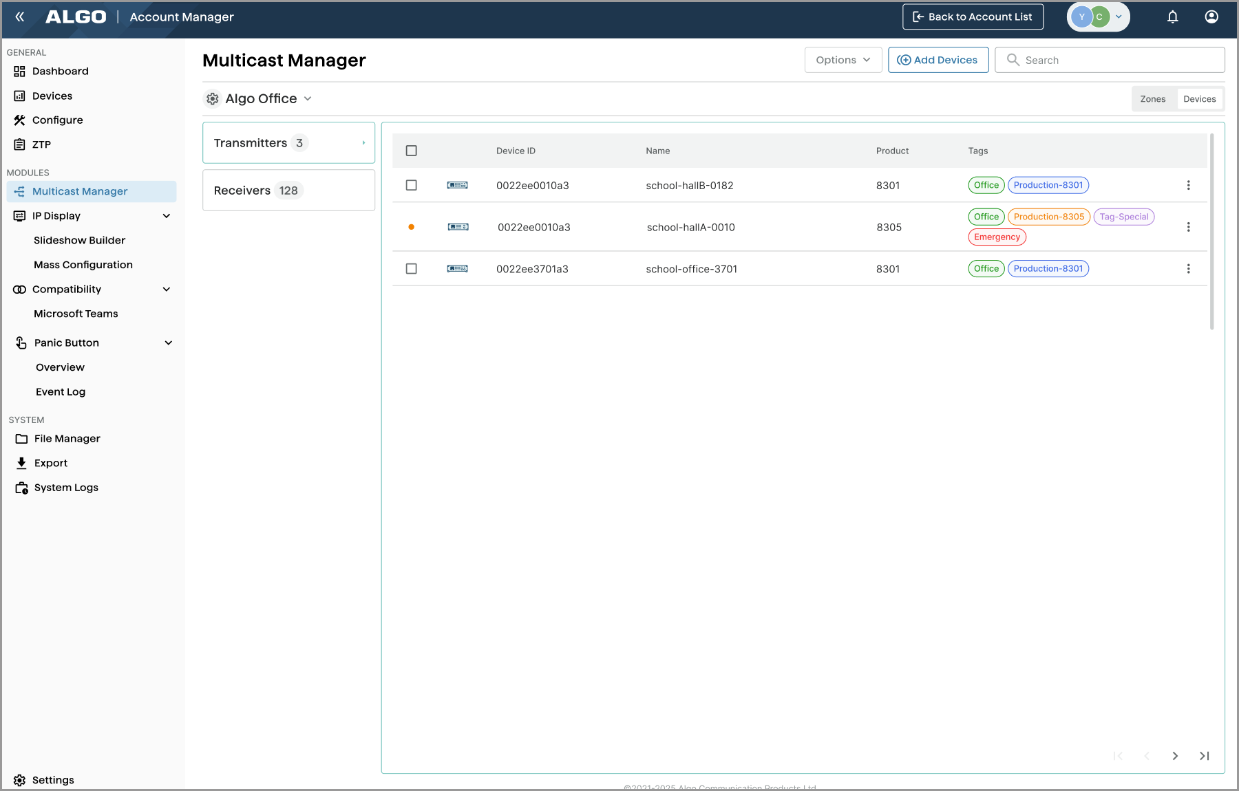
You can customize device views by showing or hiding zones or device tags that are not in use.
You can also search for devices by entering part of an ID, name, product model, or tag
Prerequisites
Make sure your device meets the following prerequisites before using the Multicast Manager:
ADMP Cloud Monitoring: Must be enabled on the device.
Allow Configuration File Sync: Must be enabled on the device.
Firmware version: Device firmware must be version 5.6 or later.
Supported devices: All Algo IP endpoints are supported. The Algo 8300 IP Controller is not supported.
Multicast Settings Synchronization Between ADMP and the Device Web Interface
Multicast settings are synchronized between ADMP and the device web interface based on the Heartbeat Interval configured in the device’s ADMP Cloud Monitoring.
To ensure timely synchronization, make sure the Allow Configuration File Sync option is enabled on the device so ADMP can query and display multicast settings stored on the device.
Note
The Multicast Manager is only intended for RTP multicast. If your device is using any of the following multicast types:
Poly Group Page
Poly Push-to-Talk
Regular RTP + Poly Group Page
Regular RTP + Poly Push-to-Talk
Do not add the device to the Multicast Manager or configure multicast settings if it is part of Poly multicasting. Otherwise, the multicast type is automatically changed to RTP.
To ensure settings synchronization between ADMP and the device web interface:
Go to Advanced Settings → Admin.
Go to the ADMP Cloud Monitoring section and set the following:
Heartbeat Interval: Select how often ADMP should check the status of your device.
Allow Configuration File Sync: Enable ADMP to query and display settings stored on the device.
Select Save.
Feature Overview
The Multicast Manager uses “site” as a configuration container where multicast settings are defined once and automatically inherited by all devices assigned to that site.
Using a site ensures consistent multicast zone settings across all devices and eliminates the need to log in to each device’s web interface to configure multicast settings individually.
Note
Site settings are applied to all devices added to it, regardless of the device’s multicast role (Transmitter, Receiver, or None). This ensures consistent multicast settings for all devices such as zone definitions, transmitter output codec, and receiver audio synchronization.
Site settings are not limited to the device’s current multicast role.
For example, if a device is currently configured as a transmitter, the site’s receiver settings will automatically apply if the device later switches to a receiver (whether the change is made through the device web interface or via Multicast Manager), and vice versa.
Follow these steps to create a site and manage your devices:
Create a site, configure site settings, and add devices to it.
Configuring Your Device's Multicast Settings
Configure the device’s multicast mode, the number of zones it listens to as a receiver, or the target zone it multicasts to as a transmitter.
About Adding Devices to the Site
When you add a device to a site, if the device has the following settings:
Multicast Mode: Transmitters or Receivers, and
Multicast Type: Regular (RTP)
The device is added to the Transmitters or Receivers section, as per its Multicast Mode setting.
Otherwise, the device is added to the Unconfigured Devices section.
.png)
Creating a Site
To use the Multicast Manager, you must first create a site and add devices to it. You can create only one site per ADMP account.
To create a site:
Go to Multicast Manager and select Create a new Site.
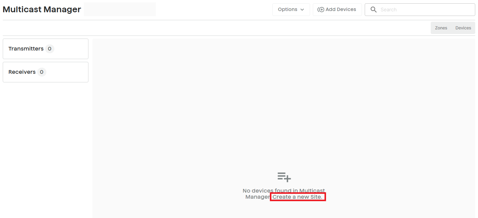
Enter a name for your site.
Configure Transmitter Settings.
Settings
Description
Transmitter Output Codec
Select an audio encoding format for the Transmitter device to use when sending output to the Receivers. Supported formats include:
G.711 ulaw
G.722
Opus
L16
Output Packetization Time (milliseconds)
Select the size of the audio packets the Transmitter sends to the Receivers from the drop-down list. The default of 20 milliseconds is recommended unless a different value is specifically required for compatibility with other devices.
Multicast TTL
Only change the multicast time-to-live (TTL) setting if custom routing is configured on the network that specifically routes multicast packets between subnets and a longer TTL is required. This ensures packets are not bounced back and forth in a network identity. When the TTL is reached, the router drops the packet.
Configure Receiver Settings.
Settings
Description
Audio Sync
When using multicast with other third-party devices that have a delay in their audio path, the audio on the 8199 may be heard slightly earlier than on these other devices. Use this feature to add a small delay on the 8199 to synchronize with these other devices.
Stream End Timeout (milliseconds, 100 ~ 1000)
Time to wait after last received packet before confirming that a multicast stream has ended. Lower values allow faster switching between streams from different zones.
Configure RTP Control Protocol (RTCP) settings.
Settings
Description
RTCP Port Selection
Select how a port will be chosen to send or receive RTCP packets:
Disabled: Disable RTCP.
Next Higher Port: RTCP packets are sent and received on the next consecutive higher port number relative to the RTP port. For example, if RTP on port N, then RTCP packets are sent to port (N+1).
Multiplexed on Same Port: RTCP packets are multiplexed with RTP packets and sent over the same UDP port as the RTP audio stream, eliminating the need for a separate RTCP port.
Note
If Next Higher Port is selected, ensure that the default multicast zone definitions are modified so that zones are only assigned to even-numbered ports, leaving the next higher odd-numbered ports free for RTCP packets.
Configure Basic Zone Definitions. Enter the IP address and port for your desired zones.
.png)
If you need more zones, configure Expanded Zone Definition.
Select NEXT.
Select one or multiple devices to add to the site. Then select NEXT.
Devices that can be added are indicated by a checkbox
(1).png) icon.
icon. If your device shows an Error
.png) icon, review the mouse-over message and resolve the issue before proceeding.
icon, review the mouse-over message and resolve the issue before proceeding. (1).png)
Review your site configurations and select Create SITE.
Changing Site Configurations
You can change the site configurations at any time.
To change the site configurations:
Go to Multicast Manager and select the Settings
.png) icon on the left of your site name.
icon on the left of your site name.(1).png)
Select Modify Site.
.png)
Change the settings.
Select Modify.
The settings apply to all devices added to the site, regardless of whether they are added as transmitters, receivers, or unconfigured devices.
Deleting a site
You can delete a site. When a site is deleted, all devices assigned to it are removed from the Multicast Manager.
Deleting a site does not affect multicast settings already applied to the devices.
To delete a site:
Go to Multicast Manager and select the Settings
icon on the left of your site name.Select Delete Site.
.png)
Select Delete.
Adding Zone Labels
You can assign a custom label to a multicast zone to make it easier to identify its purpose or location.
To add zone labels:
Go to Multicast Manager and select the Zones tab.
Select the More
 icon next to the desired zone, then select Custom Zone Label.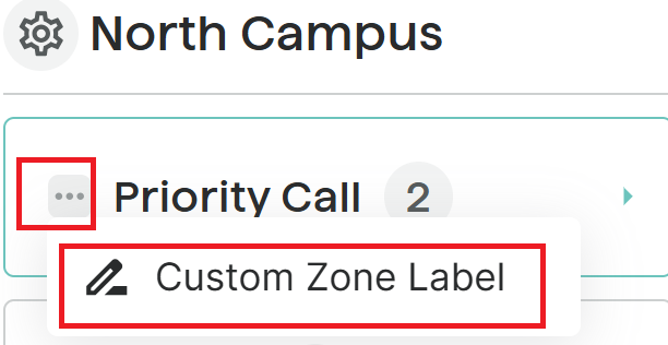
Enter the label and then select Save Changes.
Changing a Site View
By default, the Multicast Manager displays 9 basic zones, 50 extended zones, and device tags.
To create a cleaner, more concise view, you can hide unused zones or tags.
To change a site view:
To select which zones to display, do the following:
Select Zones.
Select the Settings
icon on the left of your site.Select Show/Hide Zones.
.png)
Select which zones to show, then select Apply.
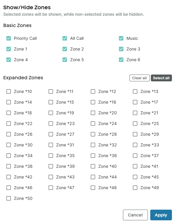
To show or hide device tags, do the following:
Select Devices.
Select the Settings
icon on the left of your site.Select Show/Hide Tags to toggle the tag view.
The setting applies to all Transmitters and Receivers.
.png)
Adding More Devices to a Site
You can bulk-add devices to a site after it is created.
To add more devices to the site:
Go to Multicast Manager.
Select Add Devices.
.png)
Select devices and then select Add.
Devices that can be added are indicated by a checkbox
.png) icon. If your device shows an Error icon, review the mouse-over message and resolve the issue before proceeding.
icon. If your device shows an Error icon, review the mouse-over message and resolve the issue before proceeding.Note
When you add a device to a site, if the device has the following settings:
Multicast Mode: Transmitters or Receivers, and
Multicast Type: Regular (RTP)
The device is added to the Transmitters or Receivers section, as per its Multicast Mode setting.
Otherwise, the device is added to the Unconfigured Devices section. You must configure its Multicast Mode later.
Removing Devices from a Site
You can remove a device from the Multicast Manager in one of the following ways:
Remove it without changing its multicast role.
You can use this option to temporarily remove devices.
Remove it and disable multicast.
You can use this option to explicitly prevent the device from participating in multicast until it is manually re-enabled.
If you add this device to the Multicast Manager again, it appears in the Unconfigured Devices section.
Removing a device does not affect the device’s other multicast configurations.
To remove devices from a site:
Go to Multicast Manager and select the Devices tab.
Depending on your device multicast role, do one of the following:
Select one or multiple devices from the Transmitters or Receivers section. Select the Options → Remove from Site.
 (1).png)
Select one or multiple devices from the Unconfigured Devices section. Then select Remove.
.png)
(Optional) To set the multicast mode to None, select Disable multicast settings for devices being removed.
.png)
Select Confirm.
Changing Device Page Volume
You can change the device’s SIP page call volume.
To change device page volume:
Go to Multicast Manager and select the Devices tab.
Select the More icon
 on the right of the desired device entry, then select Adjust Page Volume.
Select a volume and then select Confirm.
Configuring Your Device’s Multicast Settings
Configure your device’s multicast mode and the number of zones it will listen to as a receiver or multicast to as a transmitter.
Note
Your device must be online to apply multicast changes made in ADMP. Otherwise, the configuration fails.
Disconnected devices are marked with a red dot
.
Configuring Your Device as a Transmitter
You can configure the target zone and the number of zones. For IP speakers, you can also select playback zones to allow the audio to play locally on the device itself.
Note
To configure a device as a multicast transmitter, you must access the Remote Device UI. Make sure the device is connected to the Internet.
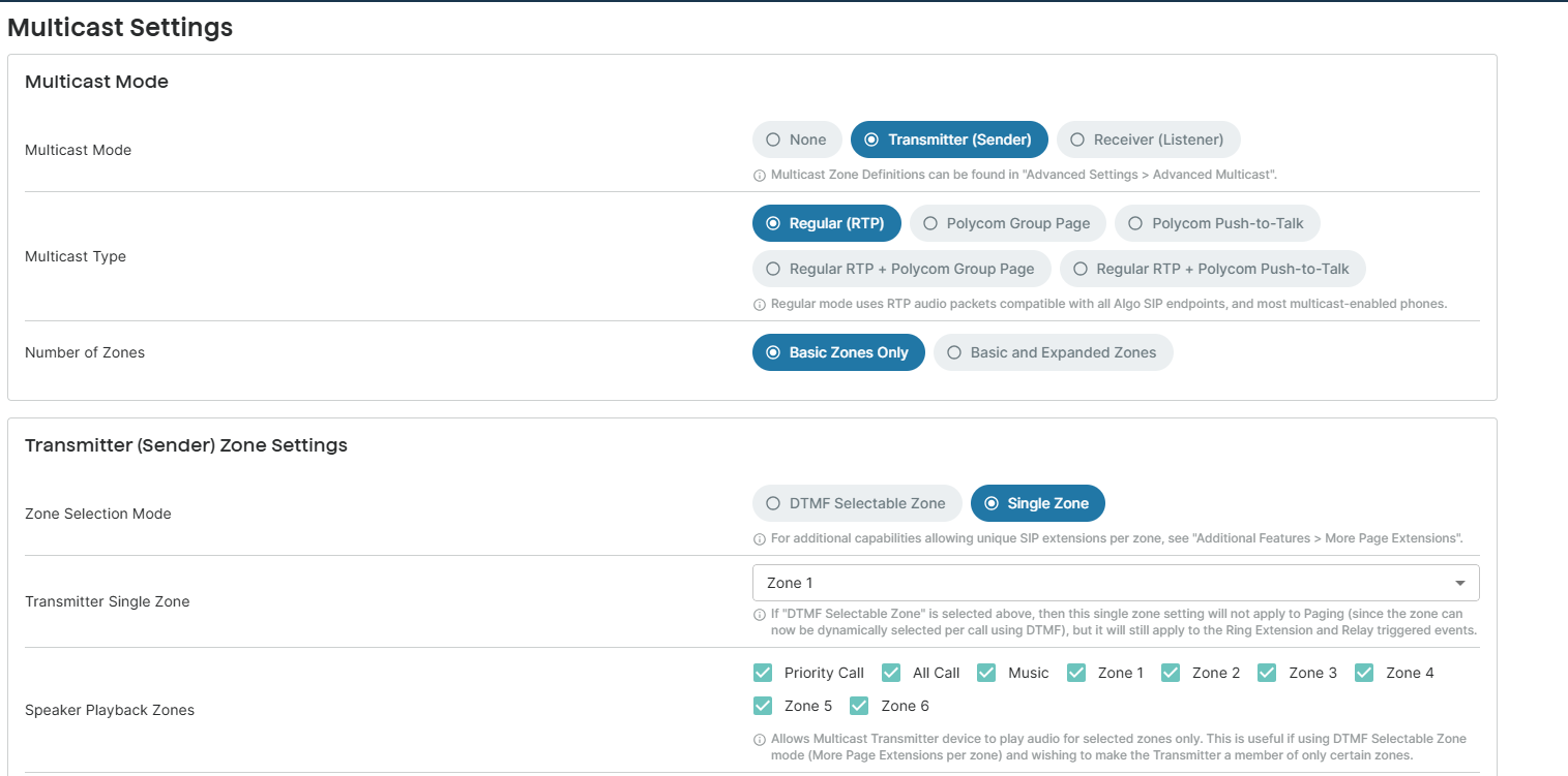
To configure your device as a Transmitter:
Go to Multicast Manager.
Do one of the following:
To set an unconfigured device as a Transmitter, select it from the Unconfigured Devices section.
To edit a Transmitter device’s settings, select a device from the Multicast Manager → Devices → Transmitters.
Select the More icon
on the right of the device entry, then select Configure as Transmitter..png)
The device’s Remote Device UI opens.
Set the Multicast Mode to Transmitter (Sender).
Configure the following:
Setting
Description
Multicast Type
Select Regular (RTP) to multicast only to Algo IP endpoints or multicast-enabled phones.
Warning
DO NOT select any of the following:
Poly Group Page
Poly Push-to-Talk
Regular RTP + Poly Group Page
Regular RTP + Push-to-Talk
This will move your device from Transmitter to Unconfigured Devices.
The Multicast Manager supports regular multicast only (RTP multicast). For multicast configurations involving Poly devices, use the device’s web interface instead.
Number of Zones
Basic Zones Only: Use only the nine basic zones.
Basic and Expanded Zones: Use the nine basic zones and 50 expanded zones.
Zone Selection Mode/Polycom Group Selection Mode
Determines how the multicast zone is selected when transmitting audio.
DTMF Selectable Zone
Allows the multicast zone to be selected during a SIP paging call using DTMF keypad input. The Transmitter Single Zone setting does not apply to paging calls in this mode.
This setting applies only to IP speakers, IP Display Speakers, and IP Paging Adapters.
When this option is selected, the device is added as a transmitter to all available zones (as defined in the device’s web interface Basic Settings → Multicast → Number of Zones). However, the active transmitting zone is determined by the DTMF tone you dial.
Single Zone
All multicast audio is transmitted to one predefined zone. No DTMF input is required.
This setting applies only to IP speakers, IP Display Speakers, and IP Paging Adapters.
Transmitter Single Zone
Select the default zone for the multicast stream to be sent to. This zone is used for multicast actions unless an option is available for a custom zone with specific parameters.
If DTMF Selectable Zone is chosen, this single zone setting will not apply to paging since the zone will be dynamically selected per call using DTMF. However, this single zone setting will still apply to the ring extension and relay-triggered events.
This setting applies only to IP speakers, IP Display Speakers, and IP Paging Adapters.
Speaker Playback Zones/Speaker Playback Groups
Allow the Multicast Transmitter device to play the audio or paging locally through its own speaker for selected zones/groups.
This is useful if using DTMF Selectable Zone mode (or More Page Extensions per zone) and wishing to make the Transmitter a member of only certain zones/groups.
This setting applies only to IP speakers, IP Display Speakers, and IP Paging Adapters.
Polycom Zone
Enter the same Multicast IP Address & Port number as configured on the Polycom phones.
Polycom Default Channel
Enter the target group in a Polycom paging environment.
Select Push to Device.
This action closes the Remote Device UI and returns you to the Multicast Manager.
Configuring Your Device as a Receiver
Configure the zones that the device listens to as a receiver.
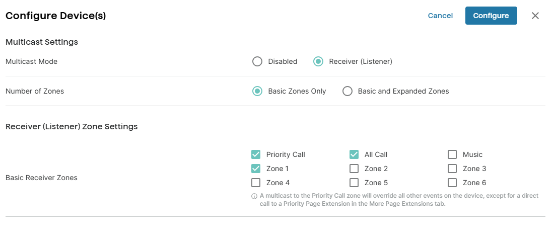
To configure your device as a receiver:
Go to Multicast Manager.
Do one of the following:
To set an unconfigured device as a Receiver, select it from the Unconfigured Devices section.
To edit a Receiver device’s settings, select a device from the Multicast Manager → Devices → Receivers.
Select the Configure as Receiver.
Set the Multicast Mode to Receiver (Listener).
Select the zones to use:
Basic Zones Only: Use only the nine basic zones.
Basic and Expanded Zones: Use the nine basic zones and 50 expanded zones.
Configure the receiver zones.
Select CONFIGURE.
Changing a Device’s Multicast Mode
To change a transmitter to a receiver, or vice versa, you must first remove it from the site and then reconfigure it.
To change a device’s Multicast Mode
Go to Multicast Manager.
Select the Devices tab, then select Transmitters or Receiver.
Select the More icon
on the right of the device entry, then select Remove from Site.Toggle on Disable multicast settings for devices being removed, then select Confirm.
Select Add Device.
Select this device and then select Add.
Go to Unconfigured Devices and select the device.
Select the More icon
on the right of the device entry, then select Configure as Transmitter, or Configure as Receiver.
Related Links:
IP Display
The IP Display feature allows you to configure connected 8410 IP Display Speakers or 8420 Dual-Sided IP Display Speakers in bulk.
For example, you can create and deploy slides or slideshows for regular visuals such as weekly announcements, clocks, or reminders.
Additionally, you can trigger the strobe light for each slide or slideshow. Moreover, you can bulk configure the connected Algo IP Display devices to specify which slides, tones, or strobe lights the 8410 or 8420 should activate when a relay, call button, announcement, or emergency alert is triggered.
This feature is beneficial for ensuring consistent content and device behavior across all IP displays in large-scale deployments.
Creating Slides
You can create slides using the Slideshow Builder.
These slides can be displayed on the IP Display screen or grouped together to present as a slideshow.
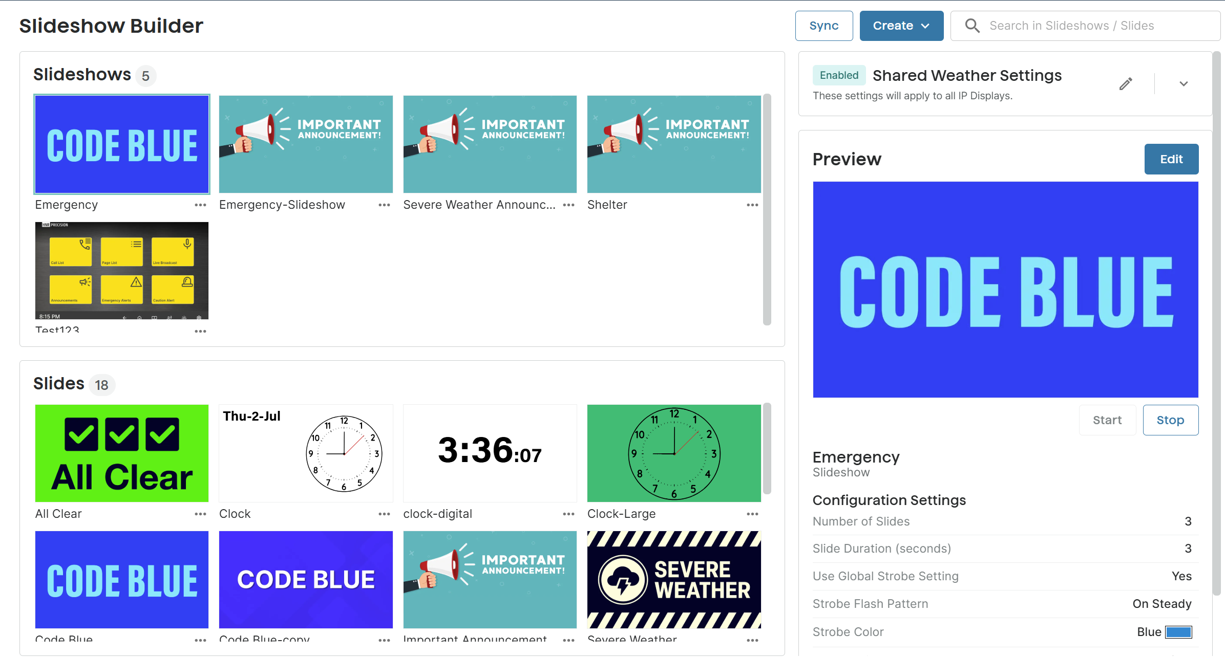
You can preview the slide effect while you are creating it.
Creating a Static Image Slide
You can create image-based slides, add still or scrolling text for additional information, and optionally enable a strobe light to display with the slide.
The strobe light is especially useful for drawing attention during emergency alerts.
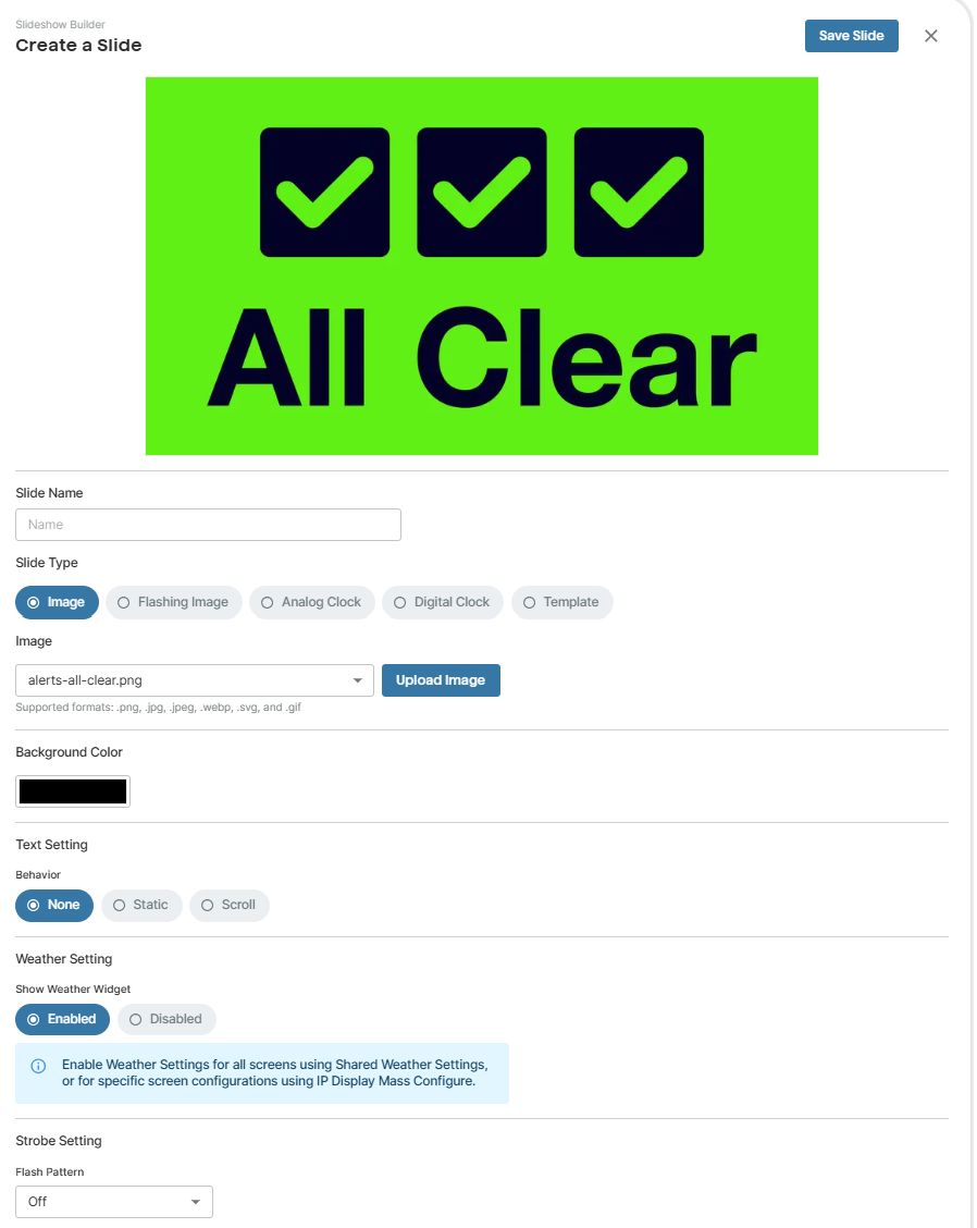
To create a static image slide:
Go to IP Display → Slideshow Builder.
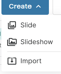
Select Create at the top right of the page.
Select Slide.
Enter a unique Slide Name at the top of the screen.
Select Image for the Slide Type option.
Select an image using Upload Image.
Note
Make sure the image file name contains only alphanumeric characters, dashes, or underscores. Otherwise, the uploading will fail.
(Optional) Set a Background Color.
If your image doesn’t fill the whole IP Display screen, the background color displays.
(Optional)Specify whether to display text along with the clock:
None: No text.
Static: Display a row of still text.
Specify the text and its appearance.
Scroll: Display a row of scrolling text.
Specify the text and its appearance.
Under Weather Settings, set whether to Show Weather Widget on the slide.
Note
To display the Weather Widget, you must also enable the following:
Use Shared Weather Settings: Set to Enabled.
Weather Settings → Weather: Set to Enabled.
To enable and configure weather information, see Displaying Weather Information.
Under Strobe Setting → Flash Pattern, set whether to activate the strobe light when the slide displays:
Off: No strobe light.
<Flash_pattern_name>: Activate the strobe light with this light pattern. You need to specify the following also:
Brightness: Set the brightness of the strobe light: Low, Medium, or High.
Color: Set the color of the strobe light.
Click Save Slide.
The slide is saved to the Slides section in the Slideshow Builder.
Creating a Flashing Slide
You can create flash-based slides to display two images alternating back and forth. This is helpful to draw extra attention to a message or alert.
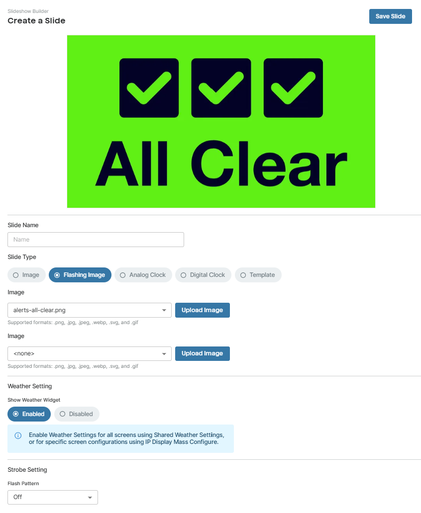
To create a flashing slide:
Go to IP Display → Slideshow Builder.
Select Create at the top right of the page.
Select Slide.
Enter a unique Slide Name at the top of the screen.
Select Flashing Image for the Slide Type option.
Select two images using Upload Image.
Note
Make sure the image file name contains only alphanumeric characters, dashes, or underscores. Otherwise, the uploading will fail.
Under Weather Settings, set whether to Show Weather Widget on the slide.
Note
To display the Weather Widget, you must also enable the following:
Use Shared Weather Settings: Set to Enabled.
Weather Settings → Weather: Set to Enabled.
To enable and configure weather information, see Displaying Weather Information.
(Optional) Under Strobe Setting → Flash Pattern, set whether to activate the strobe light when the slide displays:
Off: No strobe light.
<Flash_pattern_name>: Activate the strobe light with this light pattern. You need to specify the following also:
Brightness: Set the brightness of the strobe light: Low, Medium, or High.
Color: Set the color of the strobe light.
Click Save Slide.
The slide is saved to the Slides section in the Slideshow Builder.
Creating an Analog Clock Slide
You can create an analog clock slide to display the current time.
It provides a clear, traditional clock face that can be customized with background color, outline color, and an optional seconds hand.
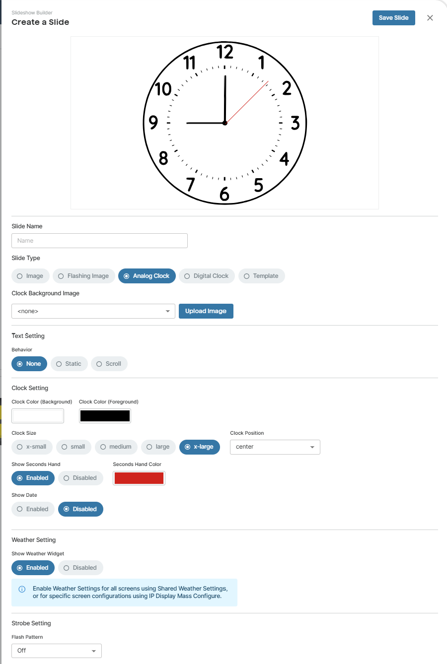
To create an analog clock slide:
Go to IP Display → Slideshow Builder.
Select Create at the top right of the page.
Select Slide.
Enter a unique Slide Name at the top of the screen.
Select Analog Clock for the Slide Type option.
(Optional) Set a Clock Background image.
(Optional)Specify whether to display text along with the clock:
None: No text.
Static: Display a row of still text.
Specify the text and its appearance.
Scroll: Display a row of scrolling text.
Specify the text and its appearance.
Configure the clock appearance.
Under Weather Settings, set whether to Show Weather Widget on the slide.
Note
To display the Weather Widget, you must also enable the following:
Use Shared Weather Settings: Set to Enabled.
Weather Settings → Weather: Set to Enabled.
To enable and configure weather information, see Displaying Weather Information.
Under Strobe Setting → Flash Pattern, set whether to activate the strobe light when the slide displays:
Off: No strobe light.
<Flash_pattern_name>: Activate the strobe light with this light pattern. You need to specify the following also:
Brightness: Set the brightness of the strobe light: Low, Medium, or High.
Color: Set the color of the strobe light.
Click Save Slide.
The slide is saved to the Slides section in the Slideshow Builder.
Creating a Digital Clock Slide
You can create a digital clock slide to display the current time. It provides clear, concise time information, and you can customize the time style.
You can also add text to the screen or activate the strobe light to draw additional visual attention.
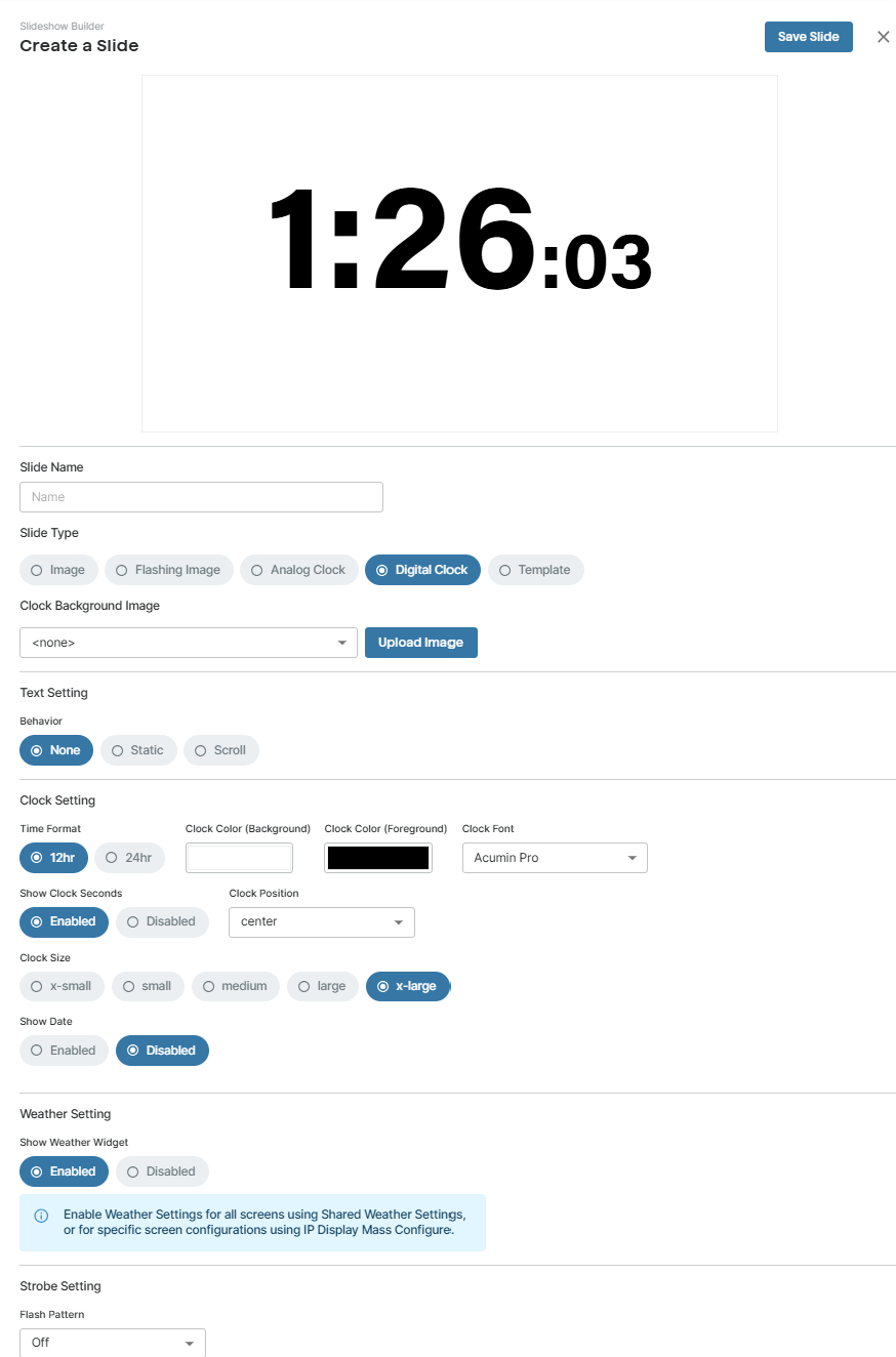
To create a digital clock slide:
Go to IP Display → Slideshow Builder.
Select Create at the top right of the page.
Select Slide.
Enter a unique Slide Name at the top of the screen.
Select Digital Clock for the Slide Type option.
(Optional) Set a Clock Background Image.
Note
Make sure the image file name contains only alphanumeric characters, dashes, or underscores. Otherwise, the uploading will fail.
(Optional)Specify whether to display text along with the clock:
None: No text.
Static: Display a row of still text.
Specify the text and its appearance.
Scroll: Display a row of scrolling text.
Specify the text and its appearance.
Configure the clock appearance.
Under Weather Settings, set whether to Show Weather Widget on the slide.
Note
To display the Weather Widget, you must also enable the following:
Use Shared Weather Settings: Set to Enabled.
Weather Settings → Weather: Set to Enabled.
To enable and configure weather information, see Displaying Weather Information.
Under Strobe Setting → Flash Pattern, set whether to activate the strobe light when the slide displays:
Off: No strobe light.
<Flash_pattern_name>: Activate the strobe light with this light pattern. You need to specify the following also:
Brightness: Set the brightness of the strobe light: Low, Medium, or High.
Color: Set the color of the strobe light.
Click Save Slide.
The slide is saved to the Slides section in the Slideshow Builder.
Creating Slides Using Preconfigured Templates
You can quickly create slides using a variety of preconfigured templates. These templates cover the most commonly used slide types, such as announcements, clocks, and calendar displays.
You can also add strobe lights, text, or a company logo to some templates.
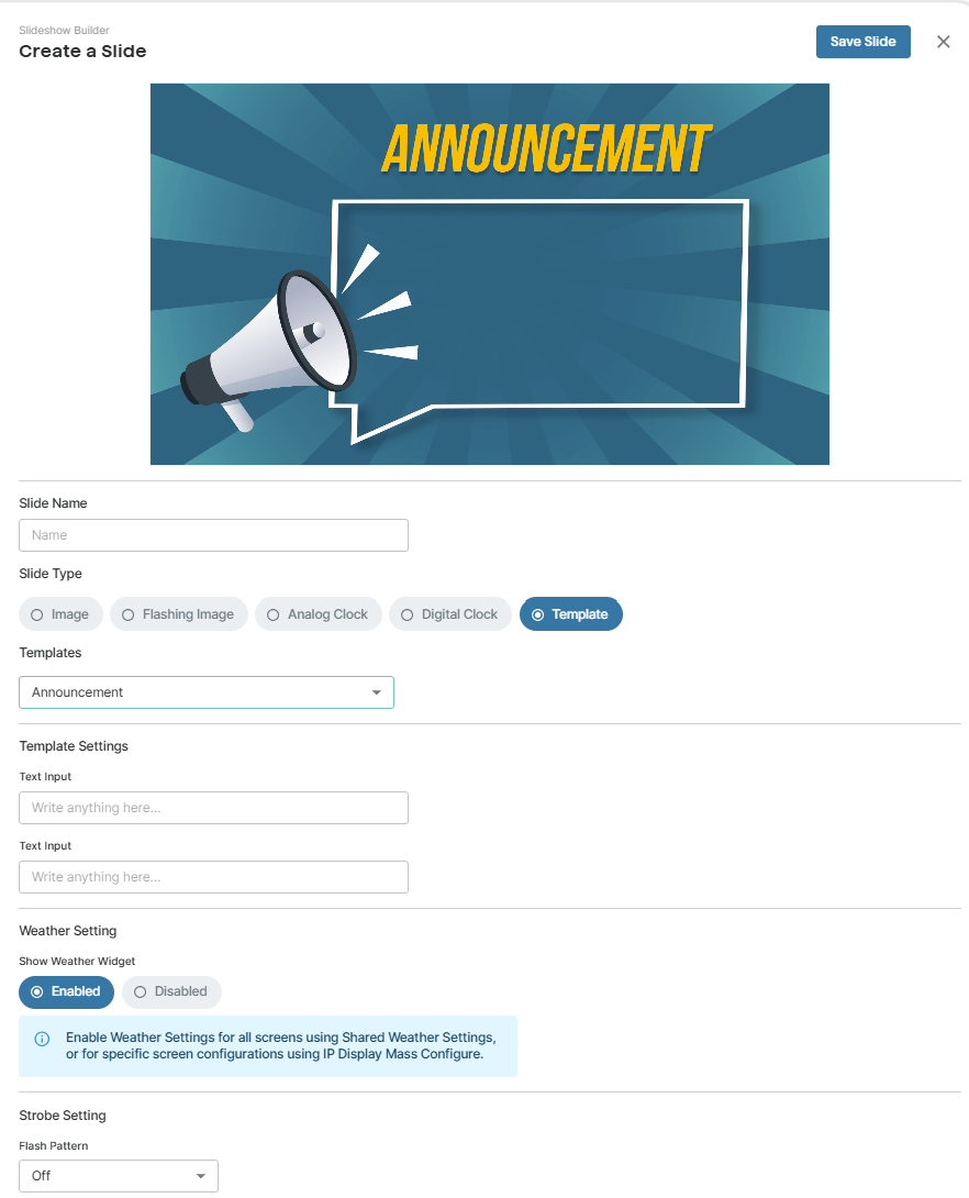
To create a slide using a template:
Go to IP Display → Slideshow Builder.
Select Create at the top right of the page.
Select Slide.
Enter a unique Slide Name at the top of the screen.
Select Template for the Slide Type option.
Select a template from the Templates drop-down list.
If the template allows text, strobe light, or clock settings, configure them as desired.
Under Weather Settings, set whether to Show Weather Widget on the slide.
Note
To display the Weather Widget, you must also enable the following under Shared Weather Settings:
Use Shared Weather Settings: Set to Enabled.
Weather: Set to Enabled.
To enable and configure weather information, see Displaying Weather Information.
Under Strobe Setting → Flash Pattern, set whether to activate the strobe light when the slide displays:
Off: No strobe light.
<Flash_pattern_name>: Activate the strobe light with this light pattern. You need to specify the following also:
Brightness: Set the brightness of the strobe light: Low, Medium, or High.
Color: Set the color of the strobe light.
Click Save Slide.
The slide is saved to the Slides section in the Slideshow Builder.
Creating Slideshows
Once you have created your slides, you can organize them into slideshows for display on IP Display screens.
Slideshows are perfect for showcasing daily announcements, schedules, reminders, and other routine updates.
Additionally, you can create new slides on the fly while you are building a slideshow.
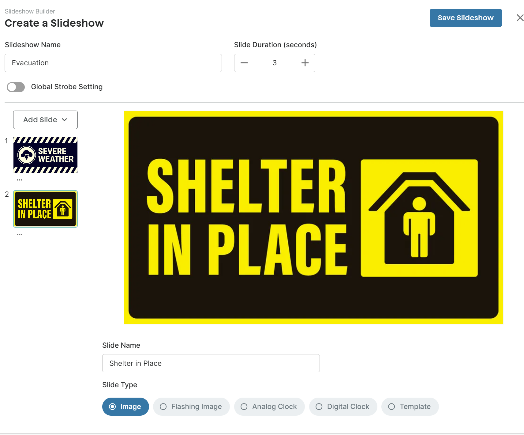
To create a new slideshow:
Go to IP Display → Slideshow Builder.
Click Create at the top right of the page. Click Slideshow.
Enter a Slideshow Name at the top of the window.
To change how long each slide displays, change the Seconds under Slide Duration.
By default, Slide Duration is set to 3 seconds.
To apply a strobe setting to go with all slides, enable the Global Strobe Setting and configure the Flash Pattern:
Off: No strobe light.
<Flash_pattern_name>: Activate the strobe light with this light pattern. You need to specify the following also:
Brightness: Set the brightness of the strobe light: Low, Medium, or High.
Color: Set the color of the strobe light.
By default, the Global Strobe Setting is turned off.
Click Add Slide on the left side of the window. Do one of the following:
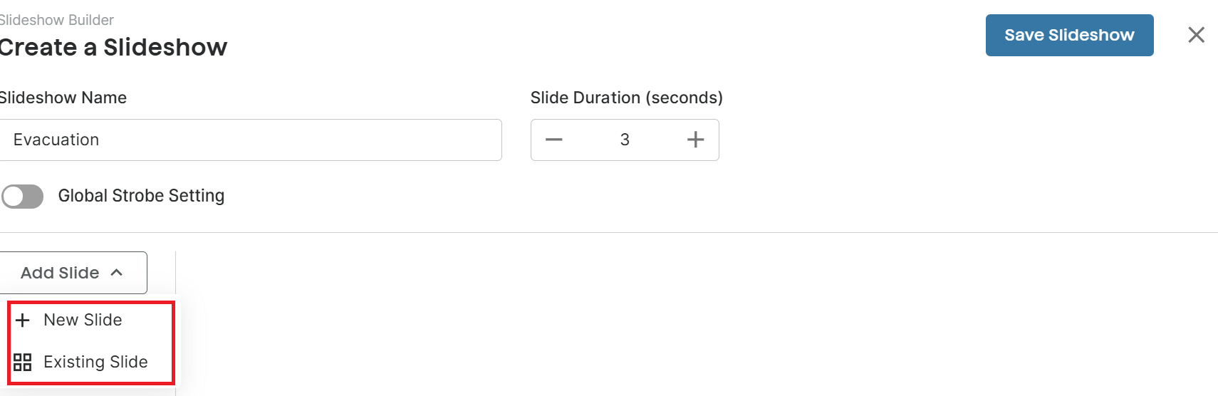
To create new slides on the fly, select New Slide.
To use slides you previously created, select Existing Slides and select the desired slides.
To edit the slideshow, do one of the following:
To add more slides, select Add Slide.
To change the order of a slide, drag and drop it to the desired position.
To delete a slide, select Delete from the More icon
below the slide.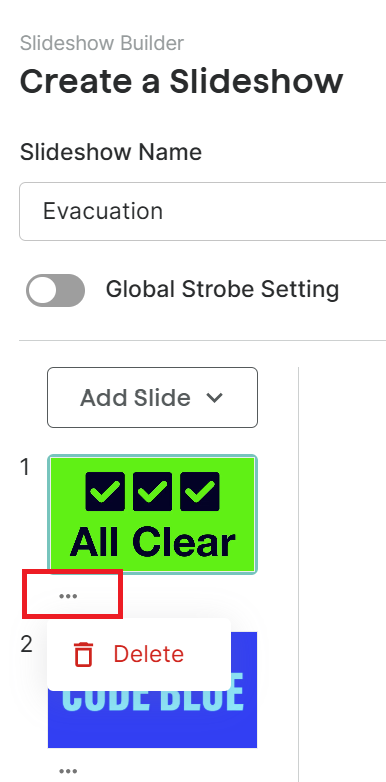
Select Save Slideshow.
The slide is saved to the Slideshows section in the Slideshow Builder.
Previewing a Slide or Slideshow
You can preview a slide or slideshow after creating it.
The file settings are also displayed in the Preview window.
Additionally, you can edit the file directly from the preview window.
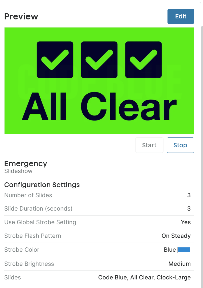
To preview a slide or slideshow:
Go to IP Display → Slideshow Builder.
Select a slide or slideshow.
The preview displays on the right side of the screen.
To stop the slideshow preview, select Stop.
Editing a Slide or Slideshow
You can edit a slide or slideshow after you have created it.
To edit a slide or slideshow:
Go to IP Display → Slideshow Builder.
Select a slide or slideshow.
The preview and file settings are displayed on the right side of the screen.
Select Edit.
Change the slide or slideshow, then select Save Slideshow or Save Slide.
Displaying Weather Information
You can display weather information on the 8410/8420 for locations in the United States or Canada using one of the following methods:
Display a full-screen weather forecast slide.
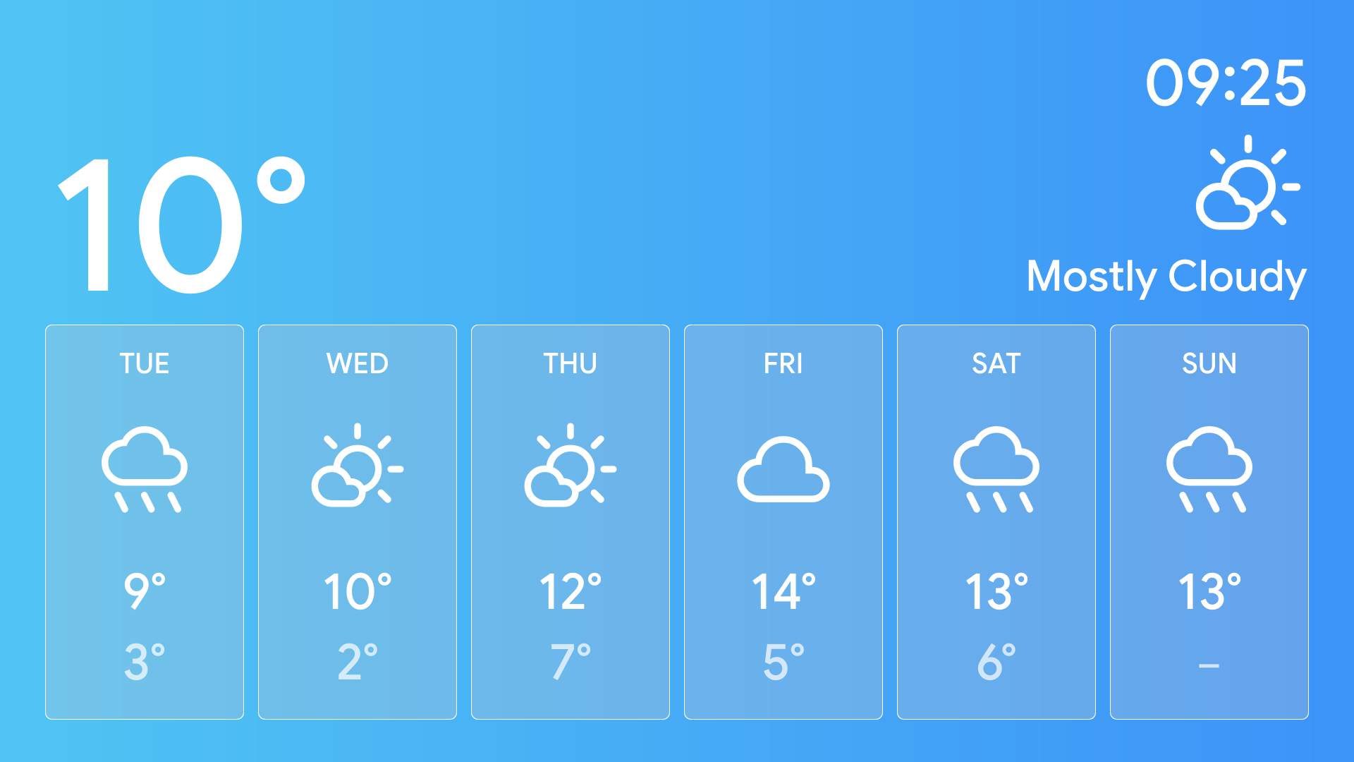
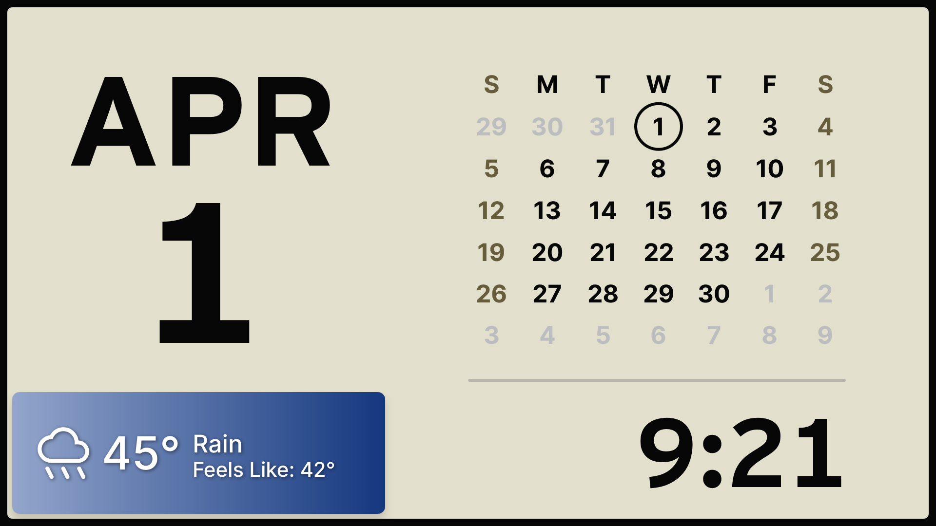
Weather - Current Conditions
Weather - Hourly Forecast
Weather - Weekly Forecast
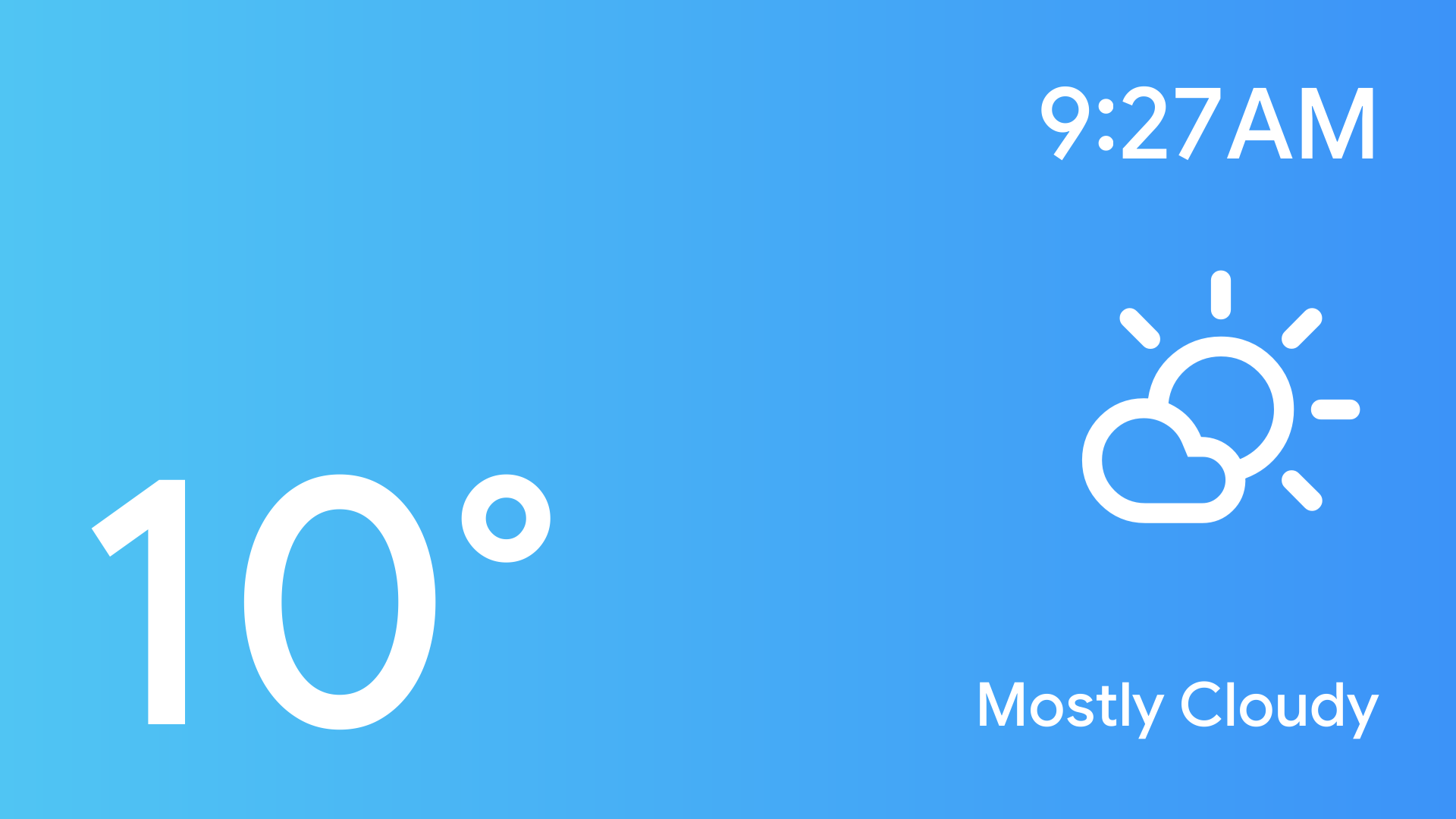
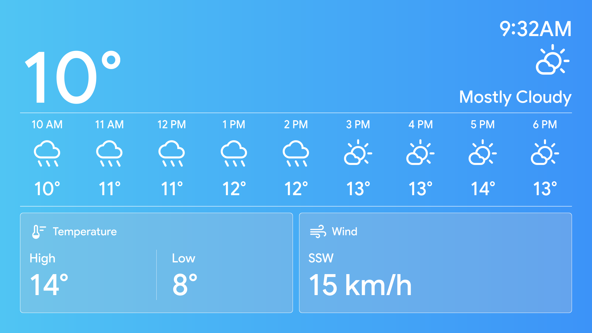
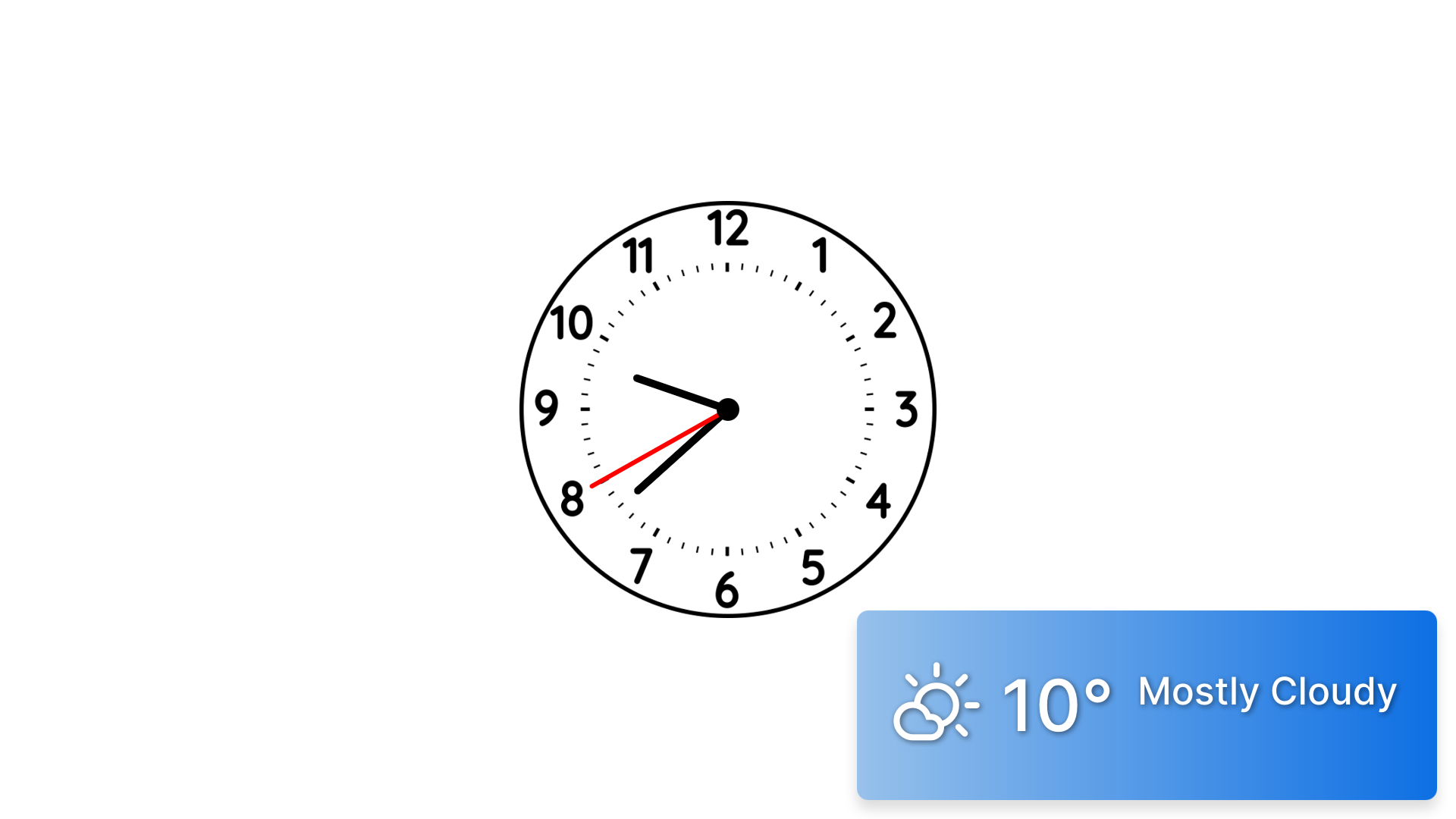
Display a Weather Widget on top of a slide or within a slideshow.
Follow these steps to configure and display weather information on your slide:
Enable and configure Weather settings using one of the following methods:
Using Shared Weather Settings, then use Sync to synchronize the settings to your IP Display.
Using a configuration file (under IP Display → Mass Configure), then use Push Config to push the settings to your IP Displays.
Enable weather information when you create a slide using one of the following methods:
Configuring Shared Weather Settings
Configure Shared Weather Settings, then use Sync to push the weather settings, along with slides, slideshows, and images, to your target IP Display devices.
Related Links:
To configure Shared Weather Settings:
Go to IP Display → Slideshow Builder.
On the upper-right of the screen, select the Edit
 icon in the Shared Weather Settings section.
.png)
Toggle on Use Shared Weather Settings.
Set Weather to Enabled.
Set the target Country to United States or Canada, then configure the detailed location:
United States: Specify the location using one of the following methods:
Enter the Latitude and Longitude (up to four decimal places, separated by a comma). For example: 38.8894,-77.0352.
You can obtain the coordinates from Google Maps by right-clicking the desired location. Round the coordinates to no more than four decimal places.
Select Find Coordinates, enter the city name, address, or zip code to find the location, then select Confirm.
.png)
Canada: Select the desired Province and Region.
Configure Weather Widget:
Widget Size: Choose a size for the widget window.
Widget Position: Choose the position of the widget.
Widget Shape: Choose an option:
Square: Displays the widget as a rectangle with slightly rounded corners.
The corner radius is 15 px radius for the Small widget size, and 10px for Medium and Large.
Rounded: Displays the widget as a rectangle with larger rounded corners (60px radius).
Select Save.
Select Sync.

When prompted, select Continue to Sync.
Select desired target devices, then select Sync.
The Sync progress bar appears. Wait till the the status shows sync successful.

Displaying Full-Screen Weather Forecast
You can use slide templates to display weather information in full-screen mode.
Note
Before using the weather slide templates, make sure weather settings are enabled and configured using one of the following methods:
Using Shared Weather Settings: Synchronize the weather settings to your device.
Using Mass Configure: Push the weather settings to your device.
To display a full-screen weather forecast:
Go to Create→ Slides.
Set Slide Type to Template.
Select an option for the Template:
Weather - Current Conditions: Displays current weather.
Weather - Hourly Forecast: Displays hourly forecast for the day.
Weather - Weekly Forecast: Displays forecast for the upcoming week.
Configure additional settings:
Time Format: Select 12hr or 24hr.
Show Clock Seconds: Whether to enable seconds display.
Headline: Show the Date, City, or None in the header.
The City option is available only for weather in the United States.
Show Feels Like: Whether to display the “feels like” temperature.
Strobe Flash Pattern: Whether to enable strobe light during display (if applicable).
Select Save Slide.
Displaying a Weather Widget
You can display current weather information as a widget overlay on slides.
Note
Before using the weather widgets, make sure weather settings are enabled and configured using one of the following methods:
Using Shared Weather Settings: Synchronize the weather settings to your device.
Using Mass Configure: Push the weather settings to your device.
To enable the Weather Widget:
Go to Create → Slide.
Go to the Weather Settings and set Show Weather Widget to Enabled.
Select Save Slide.
Importing Slides and Slideshows into ADMP
You can export existing slides and slideshows from 8410 or 8420 and import them into ADMP.
Follow these steps:
Step 1: Exporting Images and Icons from an IP Display
These files are required for the slides or slideshows.
Step 2: Exporting Slide and Slideshow Data File from an IP Display
This file contains the configuration details of the existing slides and slideshows on the device.
Step 3: Uploading Images and Icons into ADMP
Upload the images and icons, so ADMP has the necessary resources to recreate the slides and slideshows.
Step 4: Importing Slides and Slideshows Data File into ADMP
Upload the configuration file to allow ADMP to reconstruct the slides and slideshows.
Step 1: Exporting Images and Icons from an IP Display
You must export all images and icons used by the slides or slideshows. To make it easier, download all icons and images from the IP display.
To export Images and Icons from an IP Display:
Log in to your desired IP Display’s web interface.
Go to System → Maintenance.
In the Backup / Restore All User Files section, select Download.
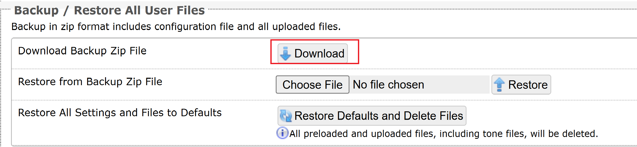
This downloads the device configuration settings and the files in the File Manager.
A .zip file named allfiles-[device model]-[MAC address].zip is saved to your computer’s default download folder.
Select the .zip file. Right-click it and select Extract All from the context menu.
You will upload the files of the images and icons folder in the ADMP File Manager later.
.png)
Step 2: Exporting Slide and Slideshow Data File from an IP Display
You can export the slide and slideshow data file from an IP display. The data file contains the configuration details for the existing slides and slideshows on the device.
After importing the images and data file into ADMP, ADMP can automatically reconstruct the slides and slideshows.
To export the slide and slideshow database file:
Log in to your desired IP Display’s web interface.
Go to Display → Data.
In the Backup / Restore Data section, select Download next to Download Slide Data File.
A database file named display-[device name]-[MAC address].db is saved to your computer’s default download folder. You will need to import this file into ADMP later.
Step 3: Uploading Images and Icons into ADMP
You need to upload the images and icons used in the slides and slideshows, so ADMP has the necessary resources to recreate them.
Log in to your ADMP application.
Go to File Manager → Images.
Select Upload. Then navigate to your extracted allfiles-[device name]-[MAC address] folder.
Select all files in the images folder and then select Open.
Go to File Manager → Icons.
Select Upload. Then navigate to your extracted allfiles-[device name]-[MAC address] folder.
Select all files in the icons folder and then select Open.
The files appear in the Images and Icons folders of the ADMP File Manager.
Step 4: Importing Slides and Slideshows Data File into ADMP
You must upload the configuration file to allow ADMP to reconstruct the slides and slideshows.
To import slides and slideshows into ADMP:
Log in to your ADMP application.
Go to IP Display → Slideshow Builder.
Select Create → Import.
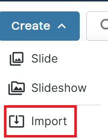
Do one of the following:
Locate your display-[device name]-[MAC address].db file. Drag and drop it into the import area.
Select Choose files. Then navigate to the display-[device name]-[MAC address].db file and select Open.
Select Import.
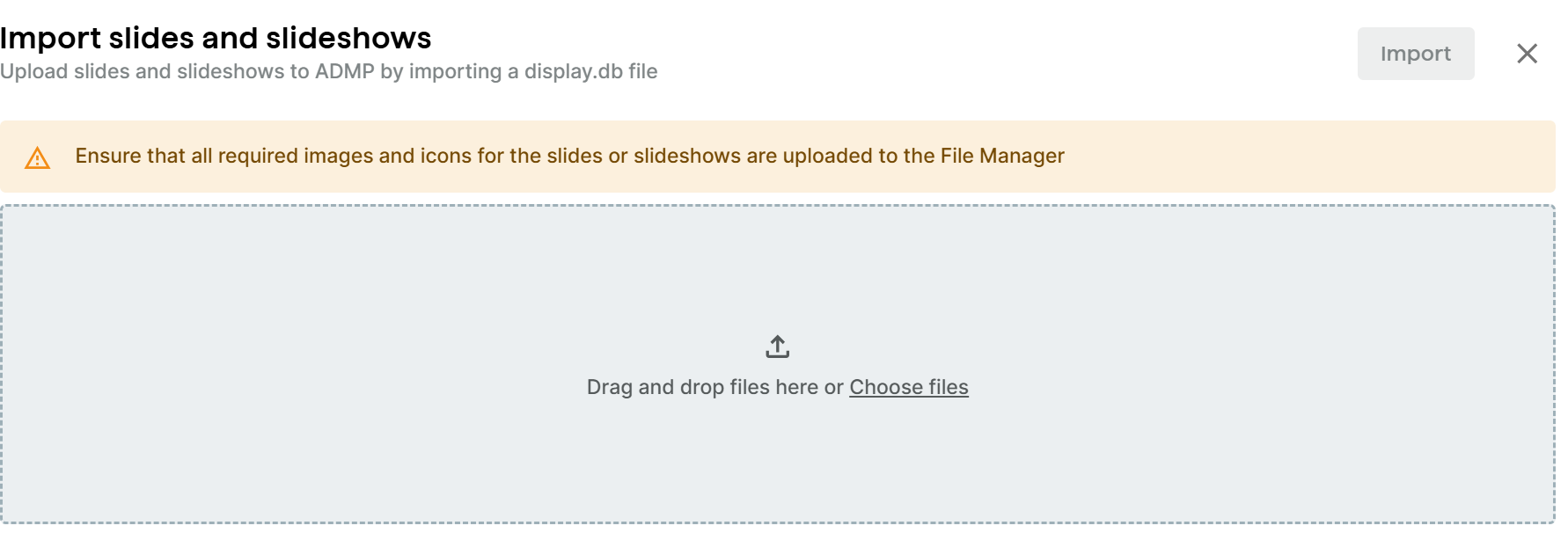
If your slide or slideshow name duplicates an existing one in ADMP, you are prompted to choose an action and then select Finish Import.
Skip: Do not import the duplicate slide or slideshow. The existing file with the duplicate name in ADMP will remain unchanged.
Import as copies: Import the duplicate slide or slideshow with a new name. For example, if the duplicate file is named "shelter," the imported file will be named "shelter-copy".
Replace: Import the duplicate slide or slideshow and overwrite the existing one in ADMP.
You can now find the recreated slides and slideshows in the Slideshow Builder.
Pushing Slides and Slideshows to IP displays
You can push all created slides or slideshows to connected Algo IP Displays.
Upon successful operation, all slides, slideshows, and associated images are pushed to the selected IP Display devices.
You can find them in the device’s web interface:
Slides are added to the Display → Slides section.
Slideshows are added to the Display → Slideshows section.
The associated images are added to the images folder in System → File Manager.
When you perform the Sync action in ADMP, existing slides and slideshows in ADMP are added to the selected devices. If a file with the same name already exists on a device, it will be overwritten. However, any files that exist only on the device and are not in the ADMP will remain unchanged.
Note
The target IP Displays must have the status Connected before you can push slides or slideshows to them.
To push all slideshow configurations to connected 8410 and 8420 devices:
Go to IP Display → Slideshow Builder.
Select Sync at the top right of the page, then select Proceed.
The system automatically selects the IP Display devices with different slides and slideshows.
When prompted, select Continue to Sync.
All slides, slideshows, and associated images are pushed to the selected IP Display devices.
Mass Configuring Algo IP Display Devices
You can bulk configure connected Algo IP Display devices to define which slides, tones, weather settings, or strobe lights the 8410 or 8420 should activate when a relay, call button, announcement, or emergency alert is triggered.
Mass configuration enables efficient deployment and ensures consistent device behavior across all IP Display devices.
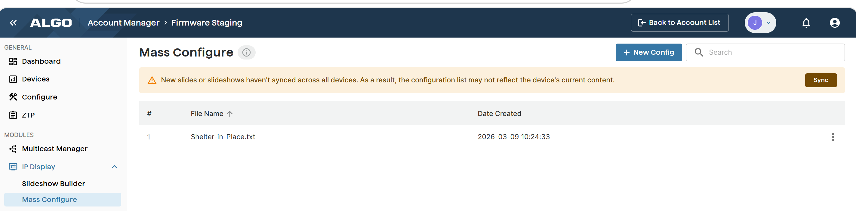
Creating Configuration Files for IP Displays
You can create up to 20 configuration files.
In a configuration file, you can define which slides, tones, or strobe lights the 8410 or 8420 device should activate when a relay, call button, announcement, or emergency alert is triggered.
To create a new configuration file for IP Displays:
Go to IP Display → Mass Configure.
Click + New Config on the top right of the page.
Enter a File Name for your configuration file.
The file names can only contain alphanumeric characters, dashes, or underscores.
Give the configuration file a clear, descriptive name to make it easy to identify later.
Configure the settings.
Select Next.
Select the IP Display devices to apply the new configuration file to.
Note
The target devices must be of the status Connected.
Review the configuration settings and click Push to Device.
Upon successful operation, the configuration takes effect on the selected devices.
Related Links:
Editing a Configuration File for IP Displays
You can edit the existing configuration file.
To edit a configuration file for IP Displays:
Go to IP Display → Mass Configure.
Select Edit from the More icon
on the right side of the desired configuration file.
IP Display Configuration File Fields
This table lists the configuration file entries and explains how each setting affects the content displayed on the 8410 or 8420 LCD screen.
Features | Description |
|---|---|
Ring/Alert Screen Pattern | Select a screen pattern to display for inbound ring events. |
Page Screen Pattern | Select a screen pattern to display for inbound page events. |
Idle Pattern | Select a pattern to be displayed on the screen for when the 8410 or 8420 is idle. Patterns can include up to several screen displays and can vary to include a single image, a notification template, a clock display, and other configurations. |
Weather Settings | Description |
|---|---|
Weather | Select whether to display weather information. |
Country | Set the target Country to United States or Canada, then configure the detailed location:
|
Weather Widget | Description |
|---|---|
Widget Size | Choose a size for the widget window. |
Widget Position | Choose the position of the widget. |
Widget Shape | Choose an option:
|
Input | Description |
|---|---|
Relay triggered Screen Pattern | Select a screen pattern to display on the screen when a relay-triggered event happens. |
Callbox triggered Screen Pattern | Select a screen pattern to display on the screen when a 1202 Call Button-triggered event happens. |
Emergency Alerts | Description |
|---|---|
Announcement N Screen Pattern (N = 1 - 10) | Select a pattern to display on the screen when announcement N is triggered. |
More Page Extensions - Basic Extensions | Description |
|---|---|
All Call Page Extension (Poly Group 8) | Select a screen pattern to display when All Call page extension is dialled. |
Screen Pattern N (Zone N) (N = 1 - 6) | Select a screen pattern to display when page extension N (N =1 - 6) is dialled. |
Music page extension (Poly Group 7) | Select a screen pattern to display when the music page extension is dialled. |
More Page Extensions - Expanded Extensions | Description |
|---|---|
Screen Pattern N (Zone N) (N= 10 - 50) | Select a screen pattern to display when page extension N (N = 10 - 50) is dialled. |
More Ring Extensions | Description |
|---|---|
Screen Pattern N (N = 2 - 10) | Select a screen pattern to display when ring extension N (N = 2 - 10) is dialled. |
Screen-tone Mapping | Description |
|---|---|
Screen Pattern N (N = 1 - 10) | Select a screen pattern to display when tone N (N = 1 - 10) plays. |
Advanced Multicast (Receiver) Screen Patterns - Basic Zones | Description |
|---|---|
Priority Call (DTMF: 9) | Select a screen pattern to display when a priority multicast is triggered. |
All Call (DTMF: 0/8) | Select a screen pattern to display when a multicast to all zones is received. |
Zone 1 (DTMF: 1) | Select a screen pattern to display when a multicast to zone 1 is received. |
Advanced Multicast (Receiver) Screen Patterns - Expanded Zones | Description |
|---|---|
Zone N (DTMF: N) (N= 10 - 50) | Select a screen pattern to display when multicast to zones 10 - 50 is triggered. |
Pushing Configurations to IP Display Devices
You can push a configuration file to connected Algo IP Displays.
Please note the following:
Only valid parameter values are accepted.
Invalid or blank parameters are ignored. No change will be made to these parameters.
To push the configurations to IP Display devices:
Go to IP Display → Mass Configure.
Select Push Config from the More icon
on the right side of the desired configuration file. 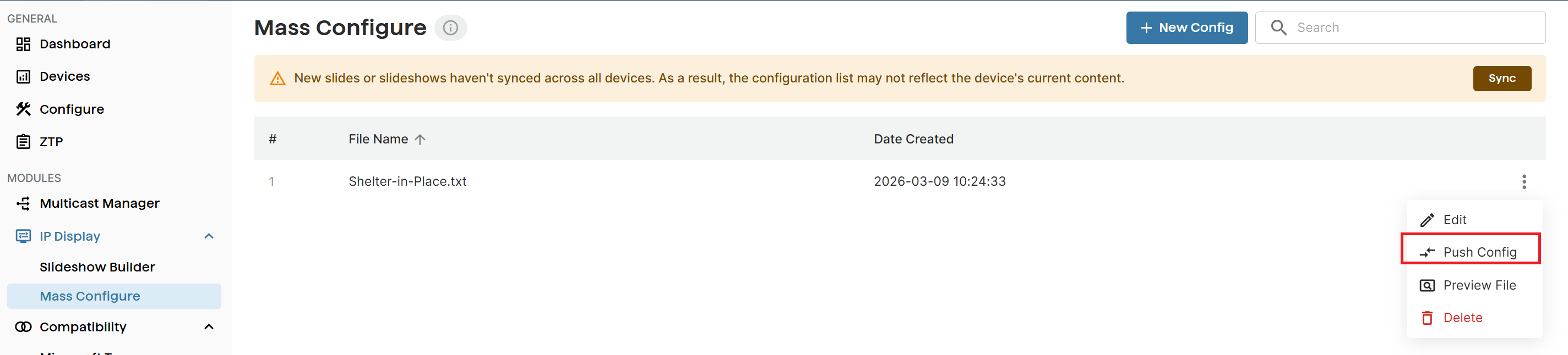
Synchronize Files and Weather Settings with IP Display Devices
To maintain consistent content and weather settings across all IP Display devices, you can push files and weather settings to the devices.
You can also choose Clean to delete slides, slideshows, and images that are not stored in ADMP. This ensures that only centrally managed content remains on connected IP Display devices.
.png)
To synchronize files and weather settings with IP Display:
Go to IP Display → Mass Configure.
Select a desired configuration file.
Select Sync.
The list of out-of-sync IP Display devices appears.
Select the desired devices.
To delete slides, slideshows, and images that are not stored in ADMP, select Clean.
Select Sync.
Microsoft Teams Configuration with Algo IP Devices Using ADMP
Algo IP endpoints are certified for native compatibility with the Microsoft Teams SIP Gateway. Applications such as IP paging, emergency alerting, and hands-free visitor communication can be implemented using both Microsoft Teams and Algo IP endpoints.
Using ADMP, you can enable Microsoft Teams support on Algo devices with an intuitive view of all Teams-enabled devices, their associated Teams accounts, and account status. ADMP also provides centralized management of Teams account configurations, eliminating the need to log in to each device’s web interface individually.
For more information, see Microsoft Teams Configuration with Algo IP Devices Using ADMP.
Beta Features
If you would like to participate in Algo’s Beta program and receive access to ADMP beta features, please contact your account representative.
[BETA] Using Paging Adapter Scheduler
For Paging Adapters, you can schedule events from ADMP for the device or other IP endpoints, including:
Play a pre-configured tone or alert to a multicast zone
Ideal for education or manufacturing environments where certain areas require regular bell schedules or announcements, while others do not.
Start a SIP call to trigger a pre-configured tone or alert on specific devices
Useful when triggering tones or announcements through the PBX for selected endpoints, such as targeted alerts, shift bells, or department-specific notifications.
Stream live audio to a multicast zone
Suitable for facility-wide announcements, background music, or emergency notifications that need to play simultaneously across all subscribed devices.
Schedule API calls from the device web interface to trigger actions on other devices
For example:
Activating a strobe light
Displaying a slide or slideshow on an IP display
Triggering an emergency alert
Triggering an InformaCast scenario
You can include up to 5 API calls in an API Call event.
For a complete list of API commands, see RESTful API Guide.
You can organize related events into a group so they can be scheduled and managed together.
You can create standalone and recurrent events, skip event or group instances in recurrent schedules, or restore skipped instances.
.png)
For more information on how to use the Scheduler, refer to:
To access Scheduler from ADMP:
Go to Devices.
Select the Connected tab, then click the Remote Device UI icon of a Paging Adapter.
.png)
Go to the SCHEDULER section and create schedules from one of the following tabs:
Calendar:
View scheduled events by month, week, or day.
Create events or groups.
Skip, delete, or restore events or groups.
Events: Create, edit, duplicate, or delete standalone events.
Groups: Create, edit, duplicate, or delete multiple events that occur within the same time frame.
Select Push to Device.
[BETA] Panic Button Monitoring
You can configure certain Relay Input accessories, physical buttons on Algo devices, and on-screen buttons on the 8450 as fully supervised panic buttons.
When configured as panic buttons, ADMP provides centralized monitoring of button status, detailed information about the associated IP endpoint, and event logs.
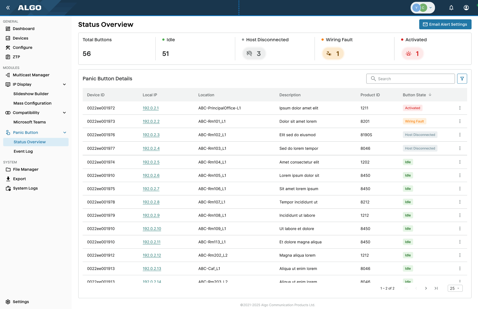
Supported Panic Buttons
This table lists supported panic buttons.
Supported Panic Buttons |
|---|
Buttons on a device:
|
Relay Input accessories:
|
Enabling Panic Button Monitoring
You must enable ADMP Cloud Monitoring and Panic Button Monitoring, and assign your desired button as the Panic Button before you can monitor their status in ADMP.
To enable ADMP Cloud Monitoring for a Panic Button:
Go to Advanced Settings → Admin.
Under ADMP Cloud Monitoring, set Enable ADMP Cloud Monitoring to Enabled.
Make sure the following is configured:
Account ID: Enter your ADMP account ID.
Allow Configuration File Sync: Enable to allow ADMP to query and display settings stored on the device.
Heartbeat Interval: Specifies how often ADMP should check the status of your device.
Enable Panic Button Monitoring: Set to Enabled.
Select Save.
Assign a button as the Panic Button:
(8028g2/8201/8203) Go to Basic Settings → Input/Output.
(8450) Do one of the following:
To assign a screen button as a Virtual Panic Button, go to the host screen of the button.
To assign the Action Button as the Panic Button, got to Additional Features → Input.
(Other devices) Go to Additional Features → Input/Output.
Configure the following:
.png)
Panic Button (or Virtual Panic Button, if applicable): Set to Enabled.
Panic Button Location: Enter a location description. For example, “Main Building Lobby”.
Panic Button Description: Enter a description for this button. For example, “Live Streaming”.
Select Save.
Log in to the ADMP web interface. The IP Endpoint appears on the Panic Button → Status Overview page.
Monitoring Panic Buttons In ADMP
You can view the overall status of all Panic Buttons, or view each button’s detailed information.
You can also download the event log to view detailed activity.
To view Panic Buttons Status:
Go to Panic Button → Status Overview.
To edit Panic Buttons details:
Go to Panic Button → Status Overview.
Select the desired entry and select More
.png) , then select Edit.
, then select Edit.Edit the button Location and Description.
Downloading Panic Button Activity Log
You can download the Panic Button activity log.
The following information is included:
Timestamp
State changes
Local IP (Host IP Endpoint’s IP)
Location
Description
To download activity logs:
Go to Panic Button → Event log.
Select Export.
Receiving Email Notification for Panic Button Alerts
You can set up to three email addresses to receive Panic Button alerts, including:
Wiring Fault
Host IP Endpoint’s connection status changes
.png)
To receive Email alert:
Go to Panic Button → Status Overview.
Select Email Alert Settings.
Enter the receiver’s email address and select Save Changes.
Email notifications are sent approximately 10 minutes after the event occurs.
Email Bounce
If an email address repeatedly bounces, ADMP stops sending notifications to that address to prevent further delivery failures. If the bounce was caused by a temporary issue (for example, a full mailbox or a temporary mail server problem), you can reactivate the email address after the issue has been resolved.
When an email address is disabled due to a bounce:
A notification appears in the Notifications window.
.png)
The email address is marked with an Error
 icon in Email Alert Settings.
To reactivate Email:
Go to Panic Button → Status Overview.
Select Email Alert Settings.
Select the bounced email, then select Reactivate.
 (1) (3)(1).png)
Select Save Changes.
Settings
The Settings screen displays your account settings and license details.
.png)
Enabling Email Notifications
You can enable email notifications to keep updated on essential device events.
To enable email notifications:
Go to Settings → Email Notification.
Enable desired event notifications:
Disconnection: You will be notified when your device is disconnected from ADMP.
Back Online: You will be notified when a device is reconnected to ADMP.
Fault Detection: You will be notified of a fault or disconnection between an Algo IP endpoint and accessory device. This includes products like Algo satellite speakers, the Algo 8028 intercom, and call buttons.
Choose the details you'd like to receive in your email notifications:
Device ID
Local IP
Name
Product
Firmware
Tags
Setting Device Table Layout
You can set the layout of the device list in the Devices page.
To set the device table layout:
Go to Settings → Device Table Settings.
Set the following:
Enable Compact View: Enabling this setting will make the rows of the device table shorter to display more devices at a time.
This can also be controlled directly on the Devices page at the bottom of the device table.
Local IP Link Protocol: Select HTTP or HTTPS to use when accessing your devices locally automatically.
This can be helpful to control, depending on the uploaded certificates and your encryption settings.
Rows Per Page: Select the number of rows in the device table to show per page.
Up to 40 can be viewed at a time. This can also be controlled directly on the Devices page at the bottom of the device table.
Feature Settings
This section displays the status of Zero Touch Provisioning.
Zero-touch provisioning is enabled by default.
To disable zero-touch provisioning, please contact the Algo support team.
Viewing Your Account Settings
You can find your account ID, account tier, and license expiry date from the Account Settings.
Setting | Description |
Your email used to log into the ADMP account. | |
Account ID | A unique ID for your company account. An Account ID is required to connect a device to ADMP. |
Tier | There are three kinds of account tiers: Trial, Pro, and Perpetual. See section 2.1 for more details. |
License Expiry | The soonest date any licenses will expire. If you have bought licenses at different times, they will have different expiration dates. However, the date listed here represents when any licenses you have will expire next. |
To view your account settings:
Go to Settings →Account Settings.
Security
Algo takes precautions to mitigate the risk of cyberattacks and builds ADMP with the safety of your data and systems in mind. ADMP and Algo devices use mutual authentication over TLS to ensure that data transferred between ADMP and the device is fully encrypted. This means only Algo devices can be used with ADMP.
ADMP does not store any unencrypted passwords.
Data at Rest
All data handled by ADMP is securely encrypted at rest with AES-256 encryption.
Port and Protocols
ADMP uses the following ports and protocols:
Address | Type | Purpose | Protocol | Security | Port | |
iot.cloud.algosolutions.com | TCP | Monitoring and management | HTTPS, MQTT, TLS | TLS 1.2 | 443 | |
files.cloud.algosolutions.com | TCP | File transfer | HTTPS, TLS | TLS 1.2 | 443 | |
dinfo.cloud.algosolutions.com | TCP | Advanced device status and relay supervision | HTTPS, TLS | TLS 1.2 | 443 | |
d1ma5gprn1j2rk.cloudfront.net/ | TCP | Pushing configurations | HTTPS, TLS | TLS 1.2 | 443 | |
firmware.algosolutions.com | TCP | Firmware upgrading | HTTPS | TLS 1.2 | 443 |