Disclaimer
The information contained in this document is believed to be accurate in all respects but is not warranted by Algo. The information is subject to change without notice and should not be construed in any way as a commitment by Algo or any of its affiliates or subsidiaries. Algo and its affiliates and subsidiaries assume no responsibility for any errors or omissions in this document. Revisions of this document or new editions of it may be issued to incorporate such changes. Algo assumes no liability for damages or claims resulting from any use of this manual or such products, software, firmware, and/or hardware.
No part of this document can be reproduced or transmitted in any form or by any means – electronic or mechanical – for any purpose without written permission from Algo.
For additional information or technical assistance in North America, please contact Algo’s support team:
1-604-454-3792
support@algosolutions.com
About
The Algo 8211 IP Single Button and Algo 8212 IP Dual Button are standalone IP buttons that connect directly to the network and initiate configurable actions. The 8211 IP Single Button contains one button and the 8212 contains two buttons. Each button supports two separate configurable actions—press and long press—giving the 8211 a total of two configurable actions and the 8212 a total of four.
The 8211 and 8212 buttons are designed to be customized for each deployment's specific needs, featuring configurable multi-color illuminated button(s), selectable faceplate labels for unique colors and text, and optional protective cover(s) to prevent unintentional button presses.
As standalone IP endpoints, the 8211 and 8212 buttons can be deployed wherever a network connection is available, providing independent device management, direct SIP registration, and device-level monitoring. The buttons can be configured as operational buttons or fully supervised panic buttons to initiate a defined communication or alert workflow. If configured as a panic button, the Algo Device Management Platform (ADMP) can provide centralized visibility into device status, connectivity, and operational readiness.
What is Included
8211 IP Single Button | 8212 IP Dual Button |
|---|---|
|
|
Installation
Note
Install the 8211/8212 and test functionality before applying the faceplate label. This label covers the mounting screws and is difficult to remove once applied.
This product is designed for indoor dry environments only.
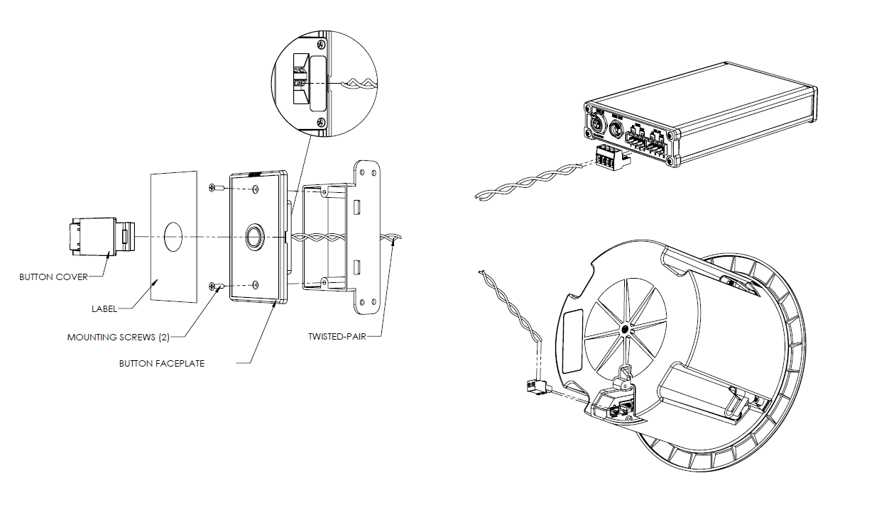
Connect the 8211/8212 to an IEEE 802.3af-compliant PoE network switch. The button illuminates steady blue until boot-up is completed (about 1 minute).
Attach the 8211/8212 to a single-gang box or low-voltage bracket using the provided flat-head screws.
Ensure the end with the Algo logo is at the top.
Note
Do not attach the faceplate label until functional testing is complete. Refer to the Getting Started section for more details.
Select the preferred faceplate label. Peel off the adhesive backing from the faceplate label and apply it to the 8211/8212 button. Ensure the label is aligned to the edge of the label indent to ensure a proper fit.
If customized product labels are required, please contact Algo Support (support@algosolutions.com).
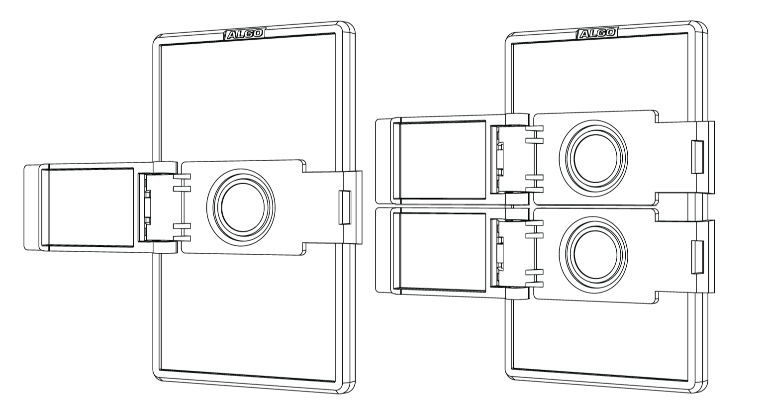
(Optional) Install the button cover by aligning it with the slots on the outside edges of the faceplate, then press down firmly along the left and right edges until the button cover snaps into place.
Note
If the button cover(s) need to be removed, insert a small screwdriver into the slot on the hinge side of the button cover to pry the cover snap away from the faceplate.
Assembling the Button Cover
The button cover consists of two pieces (Hinge Receiver and Hinge Pin) and is pre-assembled. In case you need to assemble it yourself, follow this procedure.
To assemble the button cover:
Place the Button Frame (the piece with the circular hole) with the curved ends facing upward. Position the Button Cover so the recessed side faces downward.
Insert the hinge-channel end of the Button Frame into the opening of the Button Cover, then align the axle with the two short guide channels.
Hold the two pieces at approximately 90 degrees to each other, then press both ends of the axle on the Button Cover piece until it snaps fully into the guide channels on the Button Frame.
Open and close the Button Cover to verify smooth movement and proper alignment.
Getting Started
This section walks you through the basic steps to get started with the device, including locating its IP address, accessing the web interface, securing the login password, and configuring a basic button action. Complete these steps before configuring additional device features and integrations.
Obtaining the Device IP Address
You will need the device IP address to access its web interface. You can find the device IP address using one of the following methods:
Use other network discovery methods.
Alternative Methods to Obtain Device IP
Alternatively, use one of the following methods to find devices on your local network and identify their IP and MAC addresses. All Algo devices have a MAC address starting with 00:22:ee. Use this prefix to quickly identify your Algo devices.
Log in to your router or DHCP server and check the DHCP client list.
Use a network scanning tool.
Use a network management software to view DHCP-assigned IPs.
Open a terminal or command prompt and check your ARP table:
Windows:
arp -aLinux/macOS:
arp -aorip neigh
Accessing the Web Interface
You can configure the device through its web interface. The web interface does not require an additional purchase. All settings, integrations, and file uploads can be accessed via the web interface.
To access the device web interface:
Enter the device IP address into your web browser.
Enter the login password and select Login.
The default login password is algo.
Changing the Login Password
You can change the login password. It is highly recommended to change the default password if the device is directly connected to a public network.
To change the login password:
Go to Advanced Settings → Admin → Admin Password.
Enter the Old Password.
Enter your new Password.
Repeat the new password in Confirmation.
Select Save.
The device reboots to apply the new setting.
Login Password Requirements
The login password requirements depend on the Force Strong Password setting.
Note
Before you can enable the strong password, your current login password must meet the strong password requirements listed below. If it does not, change your login password first.
Force Strong Password Enabled | Force Strong Password Disabled |
|---|---|
|
|
To enable strong password:
Go to Advanced Settings → Admin → Management.
Set Force Strong Password to Enabled.
Select Save.
Triggering Your First Button Action
This procedure demonstrates the minimum configuration required to configure a button action on the 8211.
You can use it as a reference when configuring a button action on the 8212. However, the 8212 user interface differs slightly.
To trigger your first button action:
Go to Basic Settings → Button Settings and configure the following:
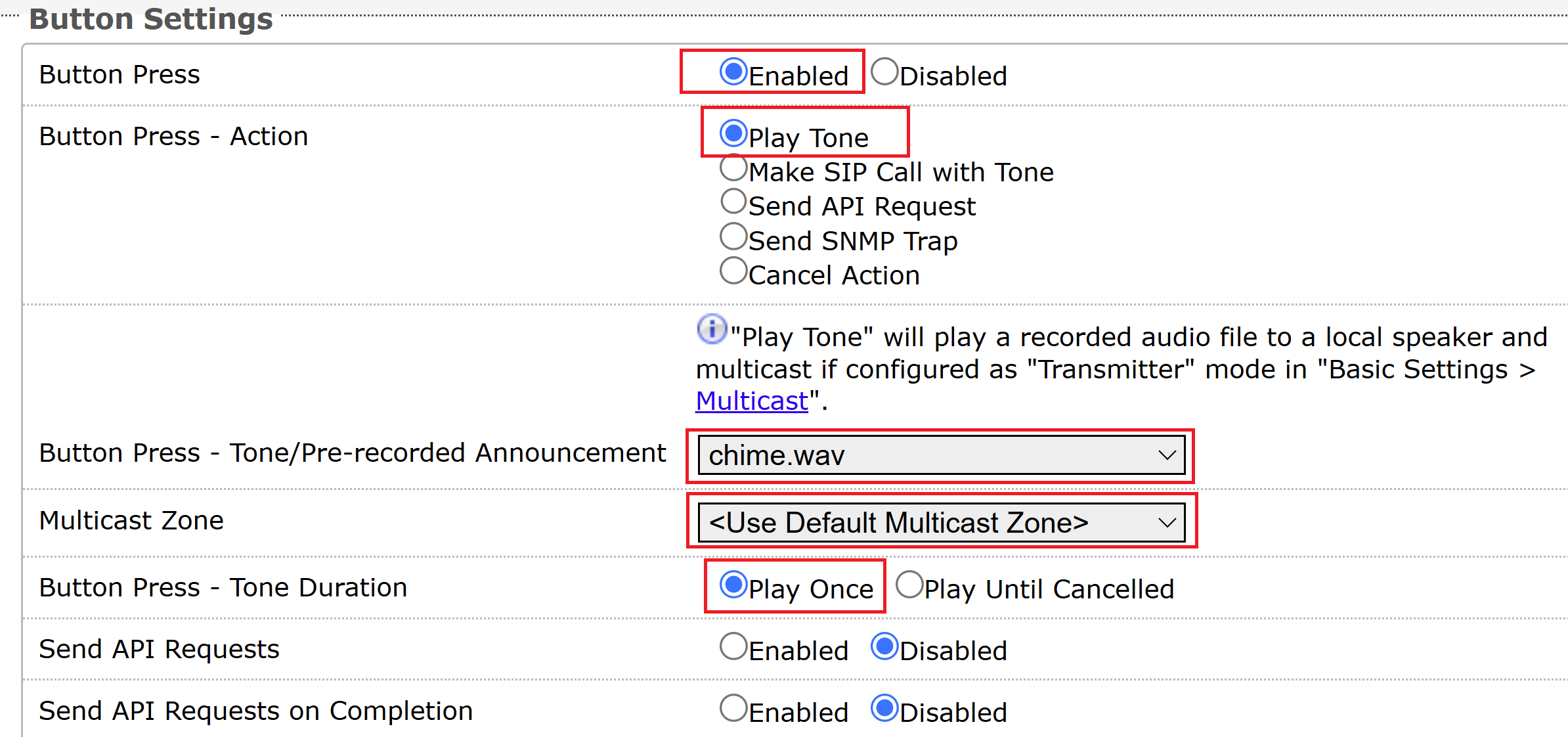
Button Press: Set to Enabled.
Button Press - Action: Set to Play Tone.
Button Press - Tone/Pre-recorded Announcement: Accept the default tone or select one.
Multicast Zone: Accept the default zone or select one.
Button Press - Tone Duration: Set to Play Once.
Select Save.
Press the button.
By default, the button ring illuminates steady red to indicate the active state.
If there are IP speakers configured as multicast receivers in your deployment, the speakers play the tone.
Device Status
The web interface has a Status page which, by default, is available both before and after login.
Depending on your device configuration and firmware version, the Status page may display the following information:
|
|
Restricting the Status Page to Logged-In Users
The Status page can be restricted to logged-in users.
To restrict the Status page to logged-in users:
Go to Advanced Settings → Admin → General.
Set Show Status Section on Status Page when Logged Out to Off.
Select Save.
Customizing Your Status Page
You can customize the content of the Status page.
To customize your status page:
Go to Advanced Settings → Admin.
Configure the General section:
Introduction Section on Status Page: Select whether to show the introduction text on the Status page.
Display Switch Port ID on Status Page: Select whether to display the switch port ID on Status page.
Select Save.
Register Your Product
Register your product to receive the latest firmware and product updates, important service notifications, and a 3-year extended warranty for IP products.
To register your product:
Do one of the following:
Scan this QR code:

Security
Algo devices use TLS for provisioning and SIP signaling to help protect against cyberattacks that attempt to intercept, replicate, or alter Algo products. Algo devices also come pre-loaded with certificates from a list of trusted certificate authorities (CA) to ensure secure communication with reputable sources. Pre-installed trusted certificates are not visible to users and are separate from those in the ‘certs’ folder under System → File Manager.
For further details, see Securing Algo Endpoints: TLS and Mutual Authentication.
Configuring SIP Extension
To place SIP calls to other devices, you need to set up a SIP extension.
To configure SIP registration:
Go to Basic Settings → SIP.
Enter the SIP server IP address or domain name in SIP Domain (Proxy Server).
Configure the following:
SIP Extension
Authentication ID
Note that some SIP servers may say Username instead of Authentication ID.
Authentication Password
Select Save.
Go to the Status page and make sure that the SIP registration is successful.
(1).png)
Now you can configure the button action as Make SIP Call with Tone to call a device or application that supports SIP calling.
Related Links:
Configuring Button Actions
You can configure the 8211/8212 button to trigger an action when the button is pressed or long-pressed. The 8212 provides two independently configurable buttons.
The available button actions allow the 8211/8212 to initiate audio multicast, outgoing SIP calls, API requests, SNMP notifications, or, cancel an active action.
Note
Button configuration procedures use the 8211 as an example. You can use them as a reference when configuring a button action on the 8212; however, the 8212 user interface differs slightly.
Understanding Button Press and Long Press Actions
Each button can respond differently depending on how you operate it:
Press: Triggers the action when the button is pressed normally.
Long Press: Triggers a separate action when the button is held for the configured Button Hold Time (seconds).
On the 8211, you can configure one Press action and one Long Press action.
On the 8212, the top and bottom buttons are configured independently. Each button can have its own Press and Long Press actions. This allows a single 8212 to provide up to four different button actions.
For example, you could configure:
Top button Press to play an alert tone.
Top button Long Press to send an API request.
Bottom button Press to make a SIP call with a tone.
Bottom button Long Press to cancel an ongoing action.
Available Button Actions
Select an action according to what should happen when the button is activated.
Action | Description |
|---|---|
Play Tone | Play a configured tone or pre-recorded announcement. The tone is multicast to a configured multicast zone. |
Make SIP Call with Tone | Play a tone or pre-recorded announcement to a configured SIP destination. The tone is multicast to a configured multicast zone. |
Start InformaCast Scenario | Trigger an InformaCast notification scenario for mass alerting and automated communications. |
Send API Request | Send one or more HTTP/HTTPS requests to another Algo device or an external system. |
Send SNMP Trap | Notify a configured network management system by sending an SNMP trap. |
Cancel Action | Cancel an ongoing action. |
Configuring an Action for a Button Press
Use this procedure when the button should immediately trigger an action when pressed.
To configure a button Press action:
Log in to the device web interface.
Go to Basic Settings → Button Settings.
Set Button Press to Enabled.
For Button Press - Action, select the action to trigger.
Configure the fields displayed for the selected action.
Refer to the following examples for common configurations:
If desired, configure additional behavior such as API requests, action cancellation, or ADMP cloud monitoring.
Select Save.
Press the button and verify that the configured action occurs.
Configuring an Action for a Button Long Press
A Long Press can provide a second function without requiring an additional physical button. The long-press action is triggered only after the button has been held for the configured amount of time.
To configure a button Long Press action:
Go to Basic Settings → Button Settings.
Set Button Long Press to Enabled.
Set Configure Button Hold Time (seconds) to the minimum amount of time the button must be held before the long-press action is triggered.
For Button Long Press - Action, select the action to trigger.
Configure the fields displayed for the selected action.
Refer to the following examples for common configurations:
To send an API request when another action starts, enable Send API Requests for that action.
To send an API request after an action finishes, enable Send API Requests on Completion.
Select Save.
Press and hold the button for at least the configured long-press time.
The configured Long Press action is triggered instead of the normal Press action.
Configuring the Button to Play a Tone
Use Play Tone when pressing the button to play a tone or pre-recorded announcement. This provides a simple way to use the button for notifications or alerts without requiring a SIP call.
This is also a useful configuration for initially testing the button.
To configure the button to play a tone:
Go to Basic Settings → Button Settings.
Enable the required Button Press or Button Long Press and configure the following.
Depending on the Multicast Type setting, the available settings may include:
Button Press - Action: Set to Play Tone.
Button Press - Tone/Pre-recorded Announcement: Select an audio file.
Multicast Zone: Select a multicast zone.
Button Press - Tone Duration: Select an option.
Interval Between Tones (seconds): Specifies the interval between tone playbacks, in seconds.
Maximum Tone Duration: Specifies the maximum playback time.
Multicast Zone: Select the target multicast zone.
Poly Group: Select the target Poly group.
Select Save.
Press or long-press the button, depending on the configured trigger.
Verify that the expected tone is played.
Note
The 8211/8212 does not play the tone directly. Instead, it multicasts the tone to devices configured as multicast receivers. If the deployment includes devices with speakers, such as Algo IP Speakers or IP Displays, those devices play the tone when they receive the multicast stream.
Configuring the Button to Make a SIP Call with a Tone
Use Make SIP Call with Tone when the button should initiate a SIP call and play a pre-recorded announcement to the destination once the call is answered.
You can place the SIP call using either of the following methods:
Through a SIP server: The 8211/8212 must be registered with the SIP server. When SIP server connectivity is available, the device places the call through the SIP server.
Using SIP Peer-to-Peer: Configure a Peer-to-Peer URI as the fallback destination. If the device cannot place the call through the SIP server, it sends the call directly to the IP address specified in the Peer-to-Peer URI. SIP server registration is not required for the peer-to-peer call. However, you must enable Peer-to-Peer.
To configure SIP registration:
Go to Basic Settings → SIP.
Configure the SIP account using the information supplied by your SIP administrator, including:
SIP Domain
SIP Extension
Authentication ID
Authentication Password
Select Save.
Go to the Status page and verify that the SIP account is successfully registered.
To enable Peer-to-Peer Calls:
Go to Basic Settings → Features → SIP Peer-To-Peer.
Set SIP Peer-To-Peer to Enabled.
Set Attempt Register to Disabled.
You must disable Attempt Register so that peer-to-peer extensions can still receive calls, but your Algo device does not attempt to register or re-register those extensions with the SIP server. Excessive SIP REGISTER attempts may result in blacklisting by the SIP server.
Select Save.
On the device’s Status page, you can see Peer-to-Peer displays as Active.
To configure the button to make a SIP call with a tone:
Go to Basic Settings → Button Settings.
Enable the required Button Press or Button Long Press and configure the following.
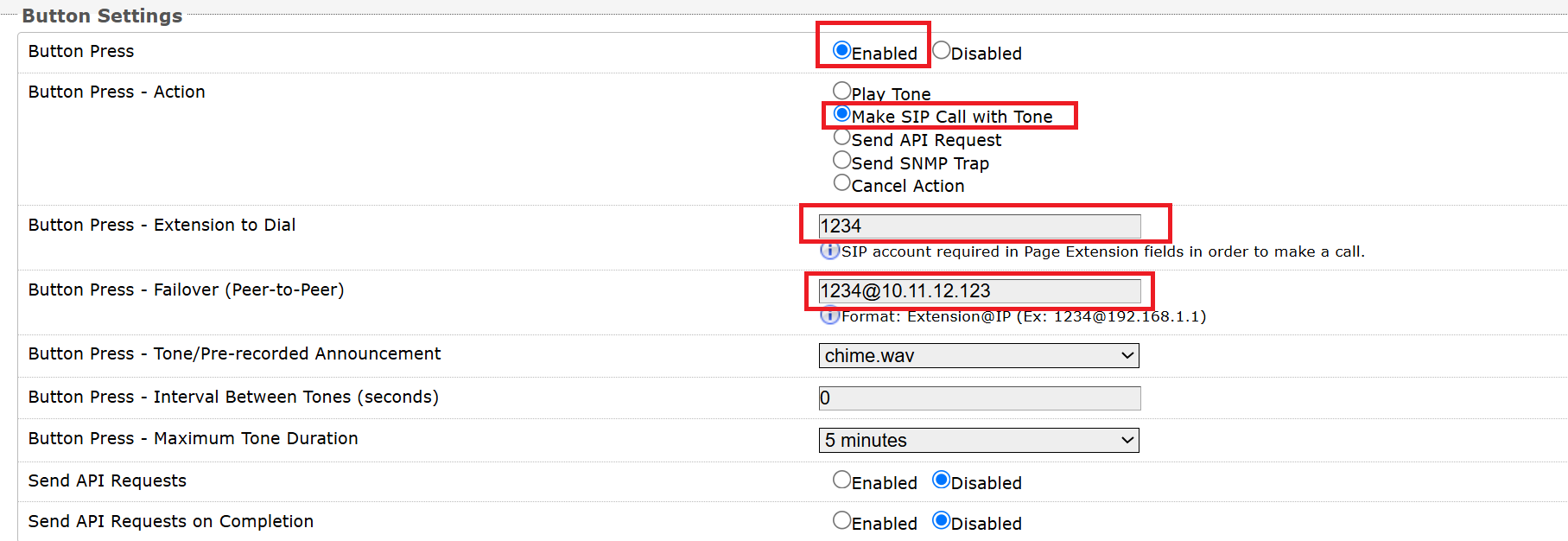
Button Press - Action: Set to Make SIP Call with Tone.
Button Press - Extension to Dial: Enter the target SIP extension.
(Optional) Button Press - Failover (Peer-to-Peer): Enter the Peer-to-Peer SIP extension in case of SIP registration failure. Enter the address in this format: <Far_End_Extension>@<Far_End_IP>.
For example, if your far-end Algo device IP is 10.11.12.123 and the SIP extension is 1234, enter 1234@10.11.12.123.
Button Press - Tone/Pre-recorded Announcement: Select an audio file.
Button Press - Interval Between Tones (seconds): Specifies the interval between tone playbacks, in seconds.
Button Press - Maximum Tone Duration: Specifies the maximum playback time.
Select Save.
Press or long-press the button.
Verify that the SIP call is established and that the expected audio is played at the destination.
Configuring the Button to Trigger an InformaCast Scenario
Use Start InformaCast Scenario when you want to trigger a predefined scenario in Singlewire InformaCast.
Before configuring the button action, enable the InformaCast Scenarios API Support and configure the credentials required to communicate with InformaCast.
To enable the InformaCast Scenarios API:
Go to Advanced Settings → Admin → InformaCast Scenarios API.
Set InformaCast Scenarios API Support to Enabled.
Enter the Security Token for the InformaCast scenario.
To include the device location when triggering the scenario, set Include Location to Enabled, then configure the applicable:
Site ID
Building ID
Floor ID
Zone ID
Select Save.
To configure the button to trigger an InformaCast scenario:
Go to Basic Settings → Button Settings.
Enable the required Button Press or Button Long Press.
Select Start InformaCast Scenario for the corresponding action.
Enter the target Scenario ID.
Select Save.
Press or long-press the button.
Verify in InformaCast that the expected scenario is triggered and that the configured notifications are delivered to the intended recipients.
Related Links:
Configuring the Button to Send an API Request
Use Send API Request to control another Algo endpoint or an external system when the button is activated.
For example, a button could send API requests to activate an alert, control another IP endpoint, or initiate an action in a third-party application.
Note
Make sure your API requests meet the following requirements:
Custom Headers: Maximum 300 characters
Headers: Maximum 1,000 characters
Data Payload: Maximum 1,500 characters
Target(s):
Maximum total target length: 500 characters
Maximum number of targets: 30
To configure the button to send an API request:
Go to Basic Settings → Button Settings.
Enable the required Button Press or Button Long Press.
Select Send API Request for the corresponding action.
Configure the required API request.
Depending on the command, the configuration can include:
Number of API Requests
Command
Data Payload
Target
Method
Custom Path
Header
Select Save.
Press or long-press the button.
Verify on the target device or application that the expected request was received and the required action occurred.
Note
When your device sends an API request to a device that requires authentication, make sure you enter the target device’s API password in Basic Settings → Features → Remote Device RESTful API Password.
The password must match the RESTful API Password configured on the target device under Advanced Settings → Admin → API Support.
Related Links:
See RESTful API Guide for a complete list of API commands, parameters, and applicable devices.
REST API Commands for a Button
Your device comes with pre-configured REST API commands to allow you to perform actions such as playing a tone, or starting a strobe light.
You can also create custom REST API commands to send API requests to any third-party devices and services that accept API requests.
API Command | Description |
|---|---|
Start Tone | Play a tone on the target device. |
Stop Tone | Stop the tone. |
Start Strobe | Turn on a strobe light. |
Stop Strobe | Turn off the strobe light. |
Start Screen | Display a screen with text, an image, or both. |
Stop Screen | Hide the screen. |
Other | Enter a custom REST API command. This allows you to send any Algo-supported REST API commands. You can also send API requests to non-Algo devices and services that accept API requests. |
Related Links:
Examples of REST API Configurations
Here are some examples of REST API configuration.
Example 1: Start a strobe light
In this configuration, when the 8211/8212 is pressed, it sends a REST API command to an Algo IP strobe (IP: 10.12.123.12) to start the strobe light, flashing in red and yellow using pattern 1 at a brightness of 100.
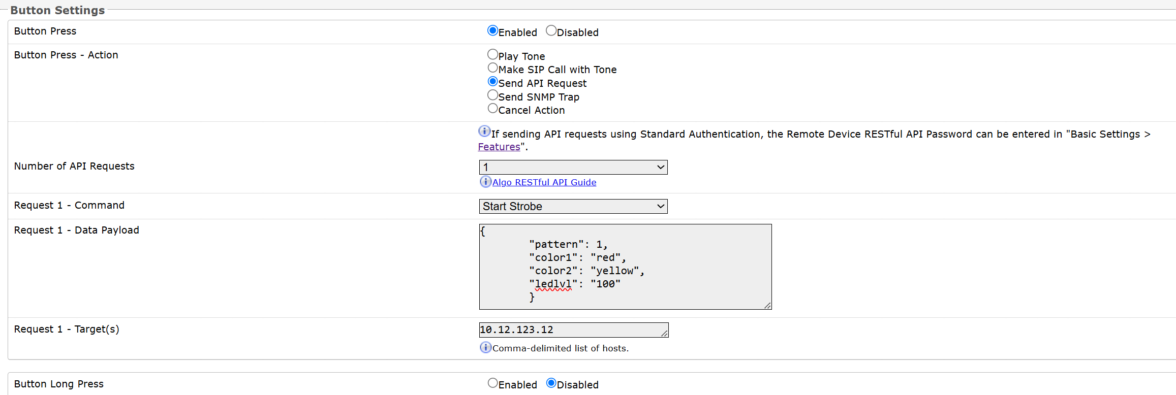
Data payload used:
{
        "pattern": 1,
        "color1": "red",
        "color2": "yellow",
        "ledlvl": "100"
        }
Example 2: Start a screen
In this configuration, when the 8211/8212 is pressed, it triggers a REST API request to Algo IP Displays (IP: 10.12.123.12 and 10.12.123.14) to display an emergency screen. The screen shows an emergency alert image with large, white scrolling text at the bottom instructing people to follow facility staff directions.
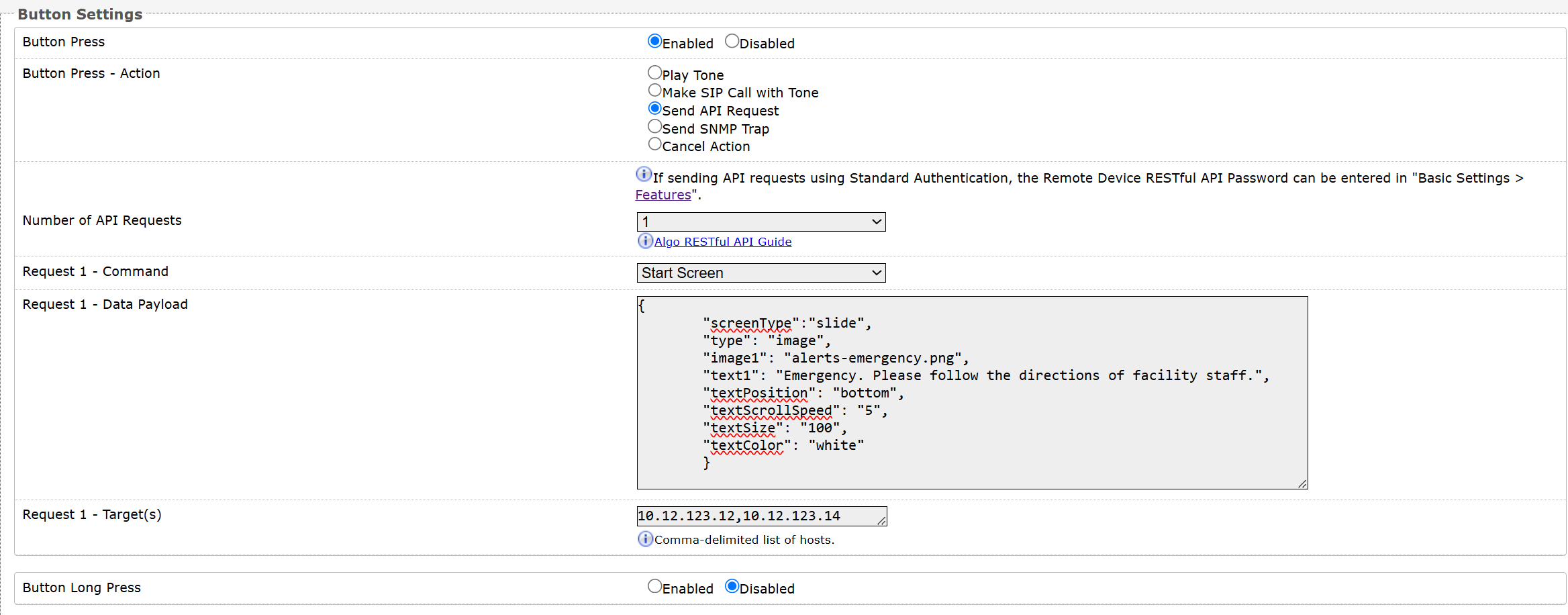
Data payload used:
{
        "screenType":"slide",
        "type": "image",
        "image1": "alerts-emergency.png",
        "text1": "Emergency. Please follow the directions of facility staff.",
        "textPosition": "bottom",
        "textScrollSpeed": "5",
        "textSize": "100",
        "textColor": "white"
        }
Example 3: Play a tone on devices
In this configuration, when the 8211/8212 is pressed, it triggers a REST API request to an Algo IP Speaker (IP: 10.12.123.12) to multicast the audio file chime.wav in a continuous loop.
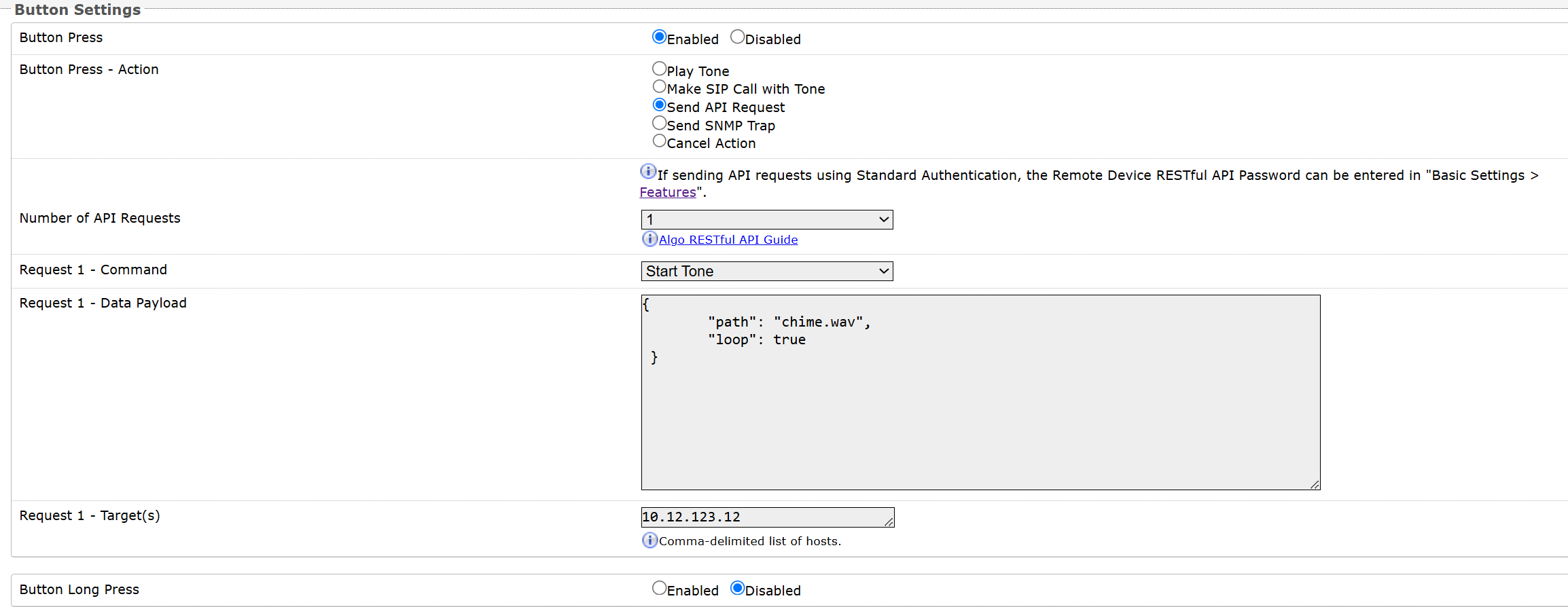
Data payload used:
{
        "path": "chime.wav",
        "loop": true
        }
Example 4: Start a multicast with a tone
In this configuration, when the 8211/8212 is pressed, it triggers a REST API request to an Algo IP Speaker (IP: 10.12.123.12) to multicast the audio file chime.wav to zone 6, in a continuous loop, without playing it locally.
The IP Speaker is configured as a multicast transmitter, with the multicast zone defined as follows: IP address 224.0.1.100 and port 50007.
Note
The multicast zone definitions (
addressandport) must match those defined in the target device’s web interface under Advanced Settings → Advanced Multicast.In this example, Zone 6 is used.
.png)
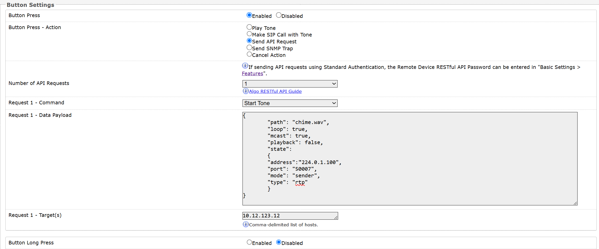
Data payload used:
{
        "path": "chime.wav",
        "loop": true,
        "mcast": true,
        "playback": false,
        "state":
        {
        "address":"224.0.1.100",
        "port": "50007",
        "mode": "sender",
        "type": "rtp"
        }
}
Example 5: Trigger a third-party application workflow
In this configuration, when the 8211/8212 is pressed, it sends a POST request with JSON data to a Microsoft Azure Logic App endpoint. This will trigger a Power Automate workflow, such as notifying a Microsoft Teams channel that an Emergency Lockdown event has been activated on the Algo 8450 in the Main Office.
Note
Replace the Custom Path with the path portion of your Power Automate workflow HTTP URL.
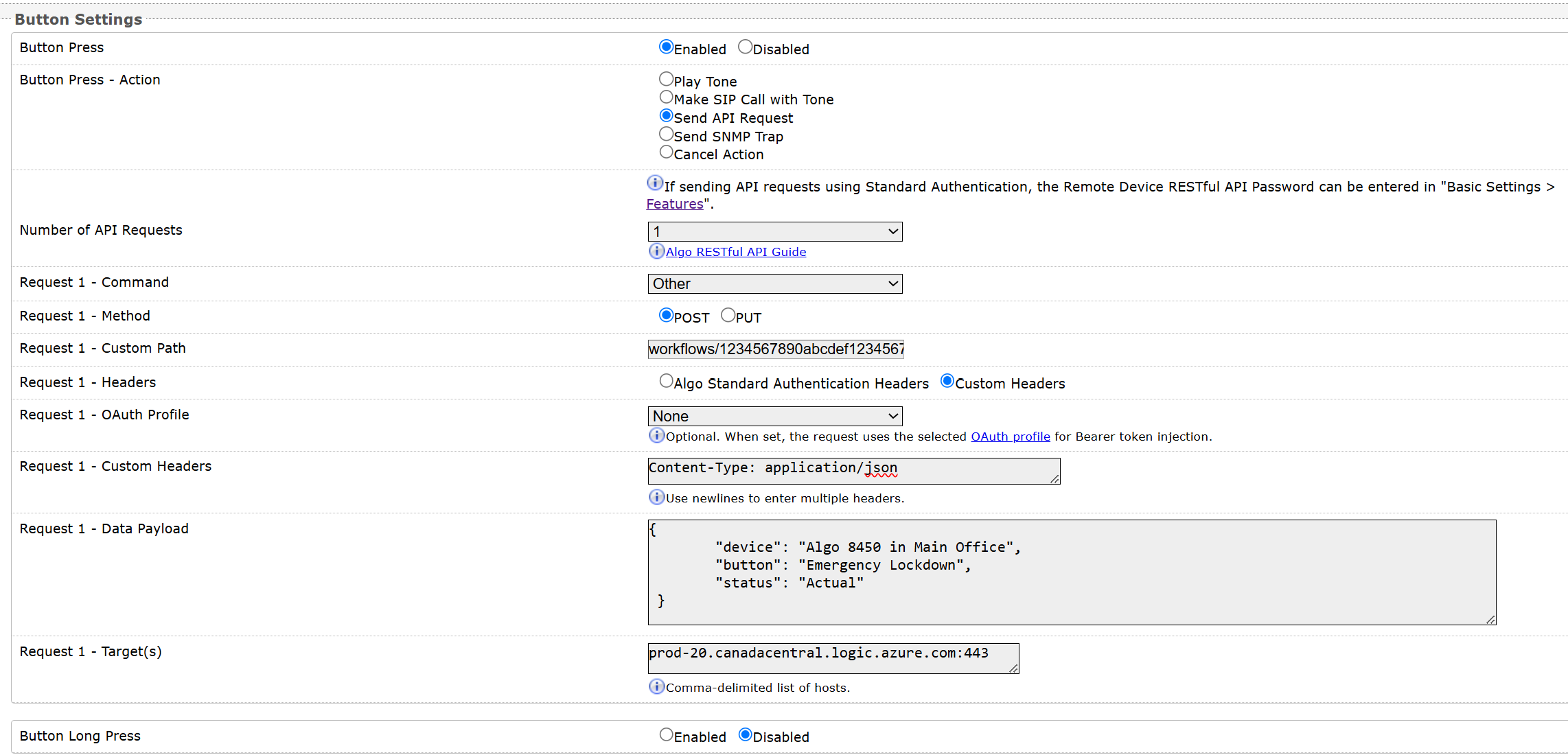
Data payload used:
Configuring the Button to Send an SNMP Trap
Use Send SNMP Trap when a network management system should be notified that the button was activated.
SNMP must be configured on the device before this action can be used.
To configure the button to send an SNMP trap:
Go to Basic Settings → Button Settings.
Enable the required Button Press or Button Long Press.
Select Send SNMP Trap for the corresponding action.
Select Save.
Go to Advanced Settings → Admin → Simple Network Management Protocol and configure SNMP settings:
SNMP Trap Remote IP: Enter the IP address of the SNMP manager or trap receiver that will receive SNMP traps.
(Optional) SNMP System Location: Enter a description of the device's location. This information helps an SNMP management system identify and monitor the device.
Select Save.
Press or long-press the button.
Verify that the configured SNMP manager receives the trap.
Cancelling, Replacing, or Overriding an Action
For actions that remain active after the initial button press, you can configure how additional button presses behave.
This is useful when you need to stop, restart, or replace an ongoing activity directly from the 8211/8212.
Note
"Send API Request" and "Send SNMP Trap" actions cannot be canceled.
Cancel Action buttons will always override other button actions.
Using the Same Button to Cancel or Restart an Action
You can cancel or restart an action by pressing the same button again.

To configure the same button to control its active action:
Go to Basic Settings → Button Settings.
Locate Allow Same Button Press to Cancel Active Action.
Select one of the following:
Disabled: Pressing the button again does not change the active action.
Cancel and Restart: Cancels the active action and immediately starts it again.
Cancel: Cancels the active action.
Select Save.
Trigger the button action and press the same button again to verify the configured behavior.
Using One 8212 Button to Override the Other Button
On the 8212, you can also define what happens when one button is pressed while an action started by the other button is active.

To configure button action override:
Go to Basic Settings → Button Settings.
Locate Allow Different Button Press to Override Active Action.
Select one of the following:
Top Button Override: Pressing the top button ends the ongoing activity triggered by the bottom button.
Bottom Button Override: Pressing the bottom button ends the ongoing activity triggered by the top button.
Both Override: Either button can end an activity triggered by the other button.
No Override: Pressing the other button does not change the ongoing activity.
Select Save.
Trigger an action from one button, and then press the other button to verify the configured override behavior.
Configuring the Button Ring Illumination Behavior
The LED-illuminated button ring provides visual feedback about the current button state.
You can configure different illumination behavior for:
Idle: No button activity is active.
Ringing SIP Call: A SIP call is being established.
Active SIP Call: A SIP call is active.
Activated: A non-SIP action is active, such as tone playback, multicasting, an API operation, or an SNMP operation.
For each state, you can independently configure the brightness, color, and illumination pattern.

To configure the button ring illumination behavior:
Go to Basic Settings → Button Settings.
Go to the Button Appearance section.
For each button state, configure:
Brightness: Off, Low, Medium, or High.
Color: Blue, Red, Green, or Amber.
Pattern:
Steady: Illumination remains on.
Slow Flash: Illumination flashes slowly.
Fast Flash: Illumination flashes rapidly.
Alarm: Illumination flashes three times per cycle.
Set Minimum Activated State Time (seconds).
This setting defines the minimum amount of time the Activated illumination remains visible for non-SIP activities. It provides visible feedback even when an action, such as an API request, completes very quickly.
Select Save.
Trigger the configured button actions and verify that the ring indicates the expected states.
Note
If a SIP call cannot be established, for example because the destination is busy, the button ring uses the alarm indication to provide visual feedback that the call attempt was unsuccessful.
Multicast
Your device can be used as a multicast transmitter and be grouped into up to 50 multicast zones. Multicast allows a single transmitting device to simultaneously send audio to multiple receiving devices over the network. Any number and combination of Algo Speakers, Paging Adapters, IP Displays, or Visual Alerters can be set as receiving devices. Receiving devices do not require a unique SIP extension and, therefore, do not need to be registered with the SIP server.
Note
The 8211/8212 is designed as a multicast transmitter, with multicast always enabled.
Key Configurations for Multicast Transmitters and Receivers
Ensure the following settings are correctly configured and consistent between the transmitter and receiver devices. These settings depend on your Multicast Mode setup:
Multicast Mode (under Basic Settings → Multicast)
Sender: Set to Transmitter
Receiver: Set to Receiver
Multicast Type (under Basic Settings → Multicast)
Both sender and receiver should be set to the same Multicast Type. Normally, it’s Regular (RTP) unless Poly devices are involved.
Zone Number (under Basic Settings → Multicast)
Confirm the Transmitter Single Zone selected on the Transmitter is also enabled under the Basic Receiver Zones on the Receiver.
Zone Definitions (under Advanced Settings → Advanced Multicast)
Verify that the IP Address and Port Number for the multicast zone match exactly on both the Transmitter and Receiver devices.
Configuring Your Device as a Multicast Transmitter
The Algo IP endpoint configured as the transmitter will multicast audio to all of the receivers simultaneously. Receiver endpoints do not require SIP extensions and do not need to register with the SIP Communication Server.
The page pre-announce tone is generated from the transmitter. The speaker volume can be increased or decreased for each multicast receiver individually.
Note
Always ensure that the multicast settings on all receiver devices match those of the transmitter.
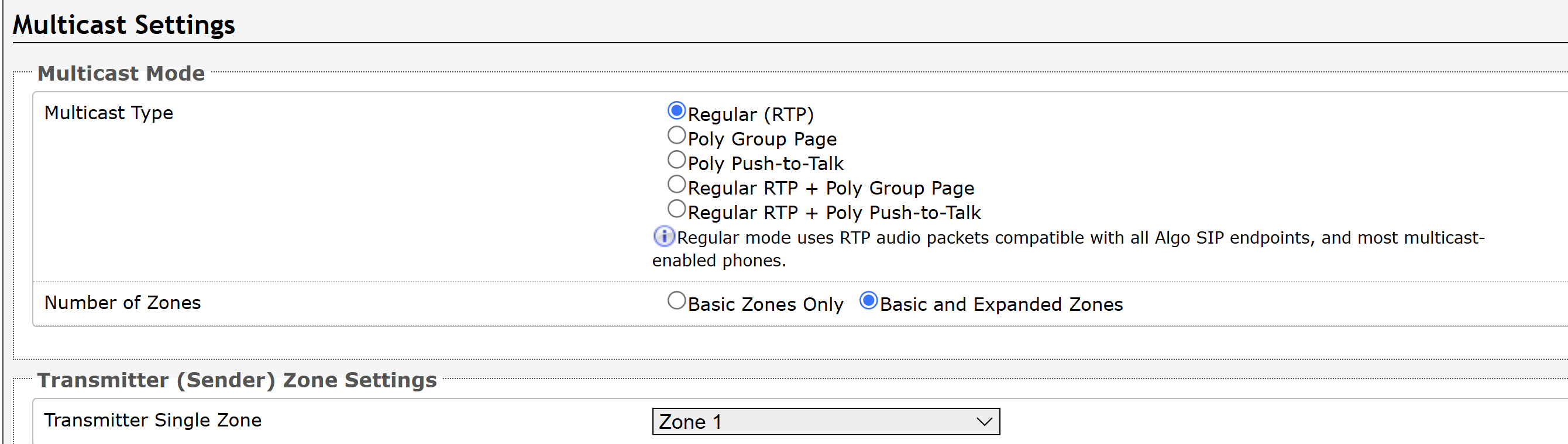
To configure your device as a Multicast Transmitter:
Go to the Basic Settings → Multicast.
Configure Multicast Mode settings:
Multicast Type: Select an option.
Regular (RTP): Multicasts only to Algo IP endpoints or multicast-enabled phones.
Poly Group Page or Poly Push-to-Talk: Multicasts to Poly phones.
Regular RTP + Poly Group Page or Regular RTP + Push-to-Talk: Multicasts to Poly phones, Algo IP endpoints, and multicast-enabled phones.
Note
Make sure your multicast receivers are set to the same Multicast Type. Normally, it’s Regular (RTP) unless Poly devices are involved.
Number of Zones:
Basic Zones Only: Uses nine or fewer multicast zones.
Basic and Expanded Zones: Uses up to 50 zones. The expanded zones have the same behavior as the basic Receiver zones but are hidden by default to simplify the interface.
For the Transmitter Single Zone option, select the default zone for the multicast audio to be sent to.
If your Multicast Mode includes Poly Group Page or Poly Push-to-Talk, configure also the following:
Poly Zone: Enter the same Multicast IP Address and Port number configured on the Poly phones.
Poly Default Channel: Selects the default group for the multicast audio to be sent to.
The Poly Default Channel is the default channel used for multicast actions unless an option is available for a custom channel with specific parameters.
Select Save.
Configuring Multicast Zones
Each device has a unique IP address and shares a common multicast IP and port number (multicast zone) for multicast packets. The transmitter units send to a configurable multicast zone, and the Receiver units listen to assigned multicast zones.
The network switches and router see the packet and deliver it to all the zone members. The multicast IP and port number must be the same on all transmitter and receiver units of the same zone. You may define multiple zones by picking different multicast IP addresses and/or port numbers.
Multicast IP addresses range: 224.0.0.0/4 (from 224.0.0.0 to 239.255.255.255).
Port numbers range: 1 to 65535.
By default, all Algo devices are set to use the multicast IP address 224.0.2.60 and the port numbers 50000-50008.
Note
Ensure the multicast IP address and port number do not conflict with other services and devices on the same network.
Make sure that the IP Address and Port Number for the multicast zone match exactly on both the Transmitter and Receiver devices.
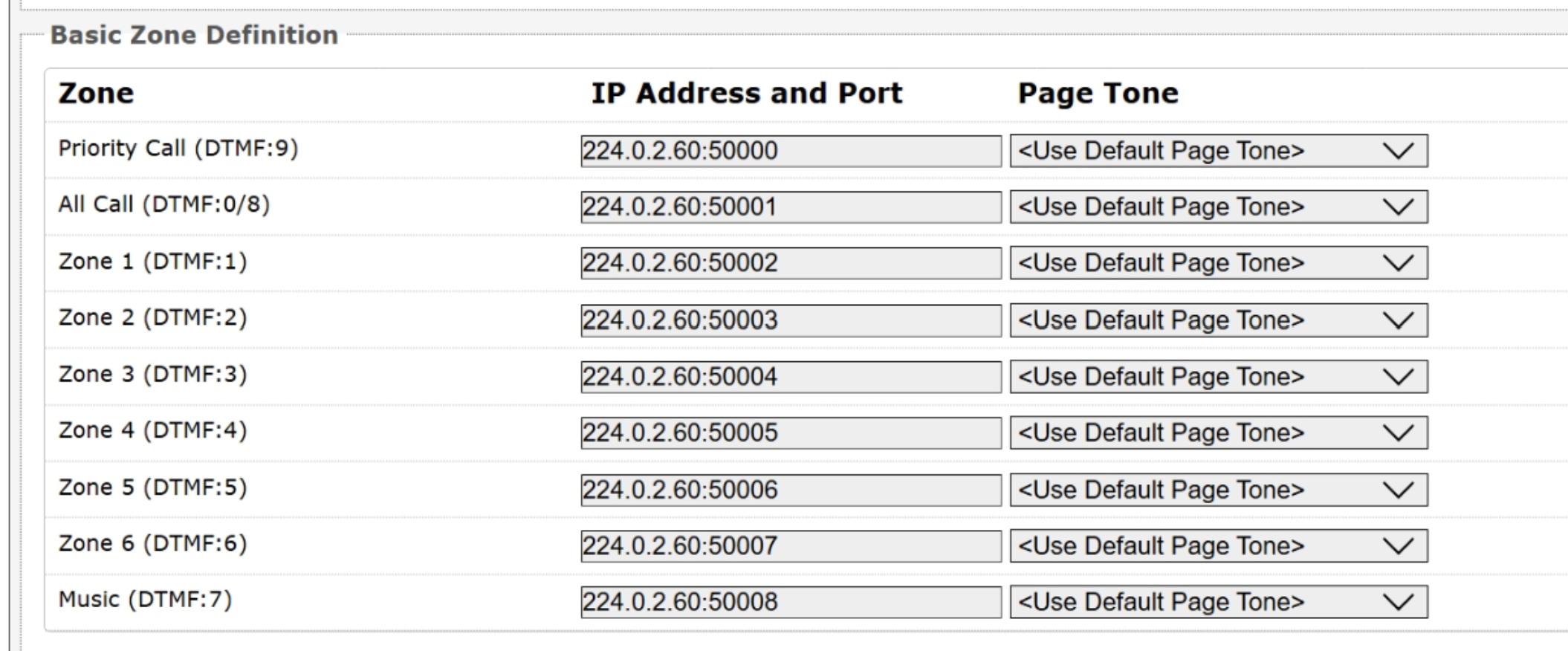
Notes
Ensure the IP Address and Port # match on both the Transmitter (Sender) and Receiver (Listener), for the zone being used.
To configure Multicast zones:
Log in to the web interface of your multicast transmitter or receiver device.
Go to Advanced Settings → Advanced Multicast.
View the default zone IP Address and Port. Edit it if necessary.
To specify a different tone to play before the multicast starts, select an audio file from the Page Tone drop-down list.
If you select <Use Default Page Tone>, the audio file specified under Basic Settings → Features → Inbound Page Settings → Page Tone plays.
Select Save.
Multicast Page Zones
By default, a multicast receiver can listen to nine basic multicast zones; however, up to 50 are available (See Additional Features → More Page Extensions for more details). The multicast IP addresses define these zones.
By default, these zones have the names below, but can be used however you prefer:
Priority
All Call
Zone 1
Zone 2
Zone 3
Zone 4
Zone 5
Zone 6
Music
Multicast Page Zone Priority
For multicast receivers, zones have a priority hierarchy where zones higher on the list will be treated with higher priority, with Music being the lowest priority. For multicast transmitters, event priority is based on the event type that initiated the multicast rather than the output multicast channel that will be active.
Multicast Triggers
As a multicast transmitter, the multicast is triggered in the following events, with the audio content broadcast to receivers in the selected multicast zone. The type of content that is broadcast depends on what triggers the multicast.
Multicast Trigger | Audio Content Included in the Multicast |
|---|---|
Button action: Play Tone | The specified tone audio. |
Button action: Make SIP Call with Tone | The tone audio. |
TLS for SIP Signaling and Provisioning
Algo devices support Transport Layer Security (TLS). This feature adds security by ensuring that Algo products can trust the hosted SIP server. This is useful for when third-party devices or attackers may try to intercept, replicate, or alter Algo products and try to connect to the server. The TLS protocol will ensure that third parties cannot read/modify any actual data. Previously, security was less of a concern because phone systems were on isolated networks, but hosted services are becoming increasingly more common. Using a hosted SIP service requires traffic to be sent over the public internet and is therefore much more susceptible to attacks. Signed certificates are important pieces in the operation of Algo devices to ensure the security, integrity, and privacy of device communication. Algo components that use TLS are Provisioning and SIP Signaling.
Algo devices come pre-loaded with certificates from a list of trusted certificate authorities (CA), which are installed in the hardware at the time of manufacture.
Note
These pre-installed trusted certificates are not visible to users and are separate from the certs folder.
The TLS handshake happens to make sure that the client and server can trust each other, and once that trust is established, the two parties can freely send encrypted data and decrypt any data that they receive. After the TLS handshake process is complete, a TLS session is established, and the server and client can then exchange messages that are symmetrically encrypted with a shared secret key.
For further details, see Algo TLS guide for SIP Signalling and HTTPS Provisioning.
Uploading Public CA Certificates
If the particular CA Certificate is not installed at factory, you can easily upload your own.
To install the public CA certificate:
Obtain a public certificate from your Certificate Authority (Base64 encoded X.509 .pem, .cer, or .crt).
In the web interface of the Algo device, navigate to the System → File Manager tab.
Upload the certificate files into the certs directory.
Click the Upload button in the top-left corner of the file manager and browse to the certificate.
Reach out to support@algosolutions.com to get the complete list of trusted certificate authorities loaded from factory.
For SIP TLS, if the Validate Server Certificate option is enabled in Advanced Settings → Advanced SIP tab, then the device will validate the SIP server against common certificate authorities.
For Provisioning, if HTTPS is selected and the Validate Server Certificate option is enabled in the Advanced Settings → Provisioning tab, then the device will validate the server against common certificate authorities.
To validate against additional certificates:
Go to System → File Manager.
Upload a Base64 encoded X.509 certificate file in .pem, .cer, or .crt format to the certs folder.
HTTPS Provisioning
Provisioning can be secured by setting the Download Method to HTTPS (under the Advanced Settings → Provisioning tab). This prevents configuration files from being read by an unwanted third-party. This resolves the potential risk of having sensitive data stolen, such as admin passwords and SIP credentials.
Note
To verify the server, enable the Validate Server Certificate option. This then checks if the certificate that is provided by the server is signed by any of the CAs included in the list of trusted CAs (used by the Debian infrastructure and Mozilla browsers). If we receive a certificate signed by any of these CAs, then that server will be trusted.
The ‘Validate Server Certificate’ parameter can also be enabled through provisioning:
Prov.download.cert = 1Using Configuration Files
When deploying your device, configuration files are used to provision the devices automatically. These configuration files define network settings, SIP credentials, and operational preferences, reducing the need for manual setup. There are two types of provisioning files available: generic and specific.
Generic configuration file: The configuration file is not tied to a specific device. It does not include the MAC address in its filename, and any Algo 8211/8212 device connected to the network can automatically download and use this file from the provisioning server. However, you must enter SIP extensions and credentials manually.
Specific configuration file: The configuration file is intended for a single device and includes the device's MAC address in the filename. Only the Algo 8211/8212 unit with the matching MAC address can download and use this file.
For more information, see Central Provisioning of Algo IP Endpoints.
MD5 Checksum
If using TFTP as a download mode, a .md5 checksum file must be uploaded to the provisioning server in addition to the .conf file. This checksum file is used to verify that the .conf file is transferred correctly without error.
To create an .md5 checksum file:
Download an MD5 tool. For example, http://www.fourmilab.ch/md5.
Extract the tool and open a command prompt in the same directory.
Run the
md5command with the target filename to generate the.md5file.To output the hash in lowercase, add the
-lparameter:Custom
md5 -l yourfilename.extThe resulting
.md5file will be saved in the same directory.
Securing SIP Signaling (and RTP Audio)
SIP signaling is secured by setting SIP Transportation to TLS (under the Advanced Settings → Advanced SIP tab). SIP transportation refers to the underlying protocol used for transmitting SIP messages between different entities in a network. Setting it to TLS ensures that the SIP traffic will be encrypted. SIP signaling is responsible for establishing the call (the control signals to start and end the call with the other party), but it does not contain the audio.
For the audio (voice) path, use the setting SDP SRTP Offer. Setting this to Optional means the SIP call’s RTP audio data will be encrypted (using SRTP) if the other party also supports audio encryption. If the other party does not support SRTP, then the call will still proceed, but with unencrypted audio. To make audio encryption mandatory for all calls, set SDP SRTP Offer to Standard. In this case, if the other party does not support audio encryption, then the call attempt will be rejected.
Integrations
The 8211/8212 supports integration with Microsoft Teams, InformaCast, and OAuth-enabled services.
These integrations allow the 8211/8212 to extend alerting and notification workflows across public address systems, SIP platforms, cloud services, and third-party notification systems.
Integration with Teams
Your device is certified for native compatibility with the Microsoft Teams SIP Gateway. Applications such as IP paging, emergency alerting, and hands-free visitor communication can be implemented using both Microsoft Teams and Algo IP endpoints.
You can configure Teams integration using one of the following ways:
Integration with InformaCast
Your device can trigger InformaCast Scenarios.
For more information, see Singlewire InformaCast Integration Guide.
Related Links:
Using OAuth for Authentication
OAuth (Open Authorization) is an industry-standard protocol that enables secure, delegated access to resources without requiring users to share credentials such as usernames and passwords.
Instead of storing static credentials on a device or application, OAuth allows a trusted third-party service (such as Google, Microsoft, or Slack) to issue time-limited access tokens. These tokens allow an Algo device to interact with the service on behalf of a user or system, without exposing sensitive login information.
For more information, see Using OAuth for Authentication.
System Maintenance
You can back up the current configuration, restore previously saved settings, reset the device to its factory defaults, and perform maintenance tasks to support troubleshooting, recovery, and device redeployment.
Monitoring your 8211/8212 Status
You can check your device status using one of the following methods:
From the Status page of the button’s web interface
This allows you to check the status of individual buttons.
From ADMP
Configure the 8211/8212 as a Panic Button so as to view its status in ADMP. ADMP allows a collective view for all panic buttons in your deployment. You can also download the event logs.
To check your button status from its web interface:
Log in to the button’s web interface.
Go to the Status page.
Configuring ADMP Cloud Monitoring for a Button
When ADMP Cloud Monitoring is enabled, the button can be identified as a panic button for cloud monitoring.
To enable ADMP Cloud Monitoring:
Go to Advanced Settings → Admin.
Go to the ADMP Cloud Monitoring section, and set Enable ADMP Cloud Monitoring to Enabled.
In Account ID, enter your ADMP account ID.
Enable Allow Configuration File Sync if you want ADMP to query and display the configuration settings stored on the device.
Set the Heartbeat Interval to specify how often ADMP checks the device status.
Set Enable Panic Button Monitoring to Enabled.
Select Save.
To configure your button as a Panic Button:
Go to Basic Settings → Button Settings.
Set Panic Button to Enabled.
Note
The Panic Button settings are available only when ADMP Cloud Monitoring is enabled.
Enter a Panic Button Location that identifies where the button is installed.
For example, Main Building.
Enter a Panic Button Description that identifies the purpose of the button.
For example, Medical Emergency.
Select Save.
To view Panic Button status in ADMP:
Log in to ADMP.
Go to Panic Button → Status Overview.
Locate your device by its IP or MAC address.
Backing Up System Configuration
Saves the device settings (configuration) and all files stored in File Manager, including certificates, licenses, and tones, to a backup ZIP file. Back up the configuration before making major changes or upgrading the firmware so it can be restored if needed.
To download the system configuration:
Go to System → Maintenance → Backup / Restore Configuration.
Select Download.
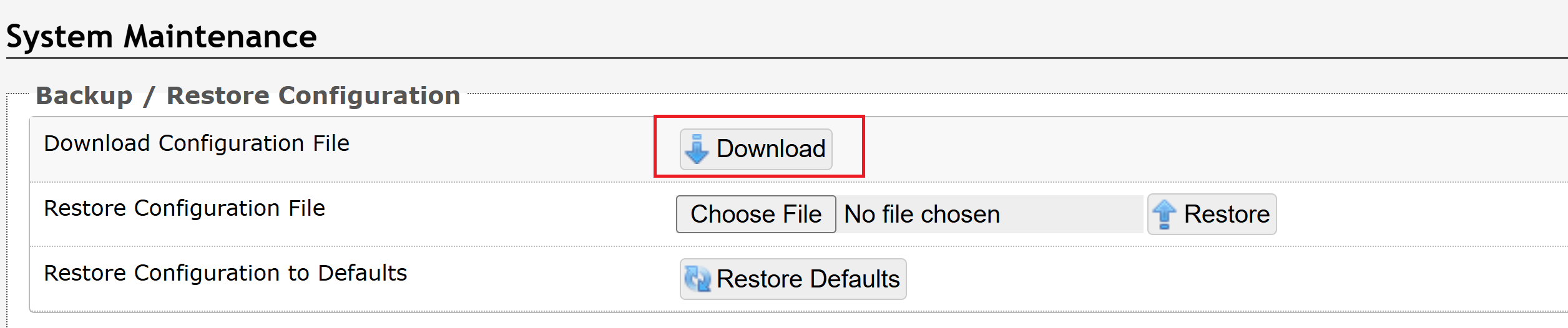
The configuration file is downloaded to your default downloads folder using the following file name format:
settings-<product_model>-<product_MAC_ADDRESS>.txt
Restoring the Device Configuration
You can restore the device configurations from a backup configuration file, or restore to its factory default settings using either the button or its web interface.
You can also choose to restore the factory default settings and delete all preloaded and uploaded files.
Restoring Settings Using a Backup Configuration File
You can restore the device settings from a backup configuration file.
To restore settings using a backup configuration file:
Go to System → Maintenance → Backup / Restore Configuration.
Select Choose File.
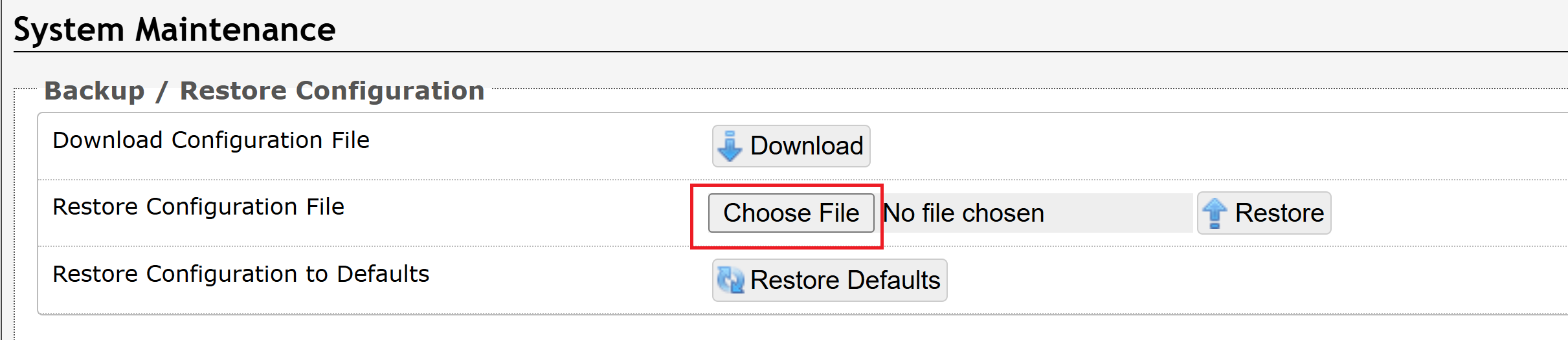
Select the configuration file, then select Restore.
The system reboots to restore the settings.
Restoring Factory Default Settings Only
Restore the factory default settings while keeping all preloaded and uploaded files. You can perform this operation using either the button or the device's web interface.
To restore the factory default settings from your web interface:
Go to System → Maintenance → Backup / Restore Configuration.
Select Restore Defaults.

When asked to confirm this action, select OK.
The system reboots to restore the default settings.
Restoring Factory Default Settings and Deleting Files
You can restore the device to its factory settings and delete all preloaded and uploaded files.
This is useful when redeploying the device or performing a complete factory reset.
To reset the factory default settings and delete files:
Go to System → Maintenance → Backup / Restore Configuration → Restore Defaults and Delete Files.

When asked to confirm this action, select OK.
The system reboots to restore the default settings. All preloaded and upload files are also deleted.
Managing Firmware
The Online Upgrade feature checks whether a newer firmware version is available from the Algo firmware server (firmware2.algosolutions.com). The device must have an active internet connection to perform this check.
Note
During the firmware update process, Algo devices communicate with two different hosts:
firmware2.algosolutions.com: Checks whether a newer firmware version is available.
algofw.sfo3.cdn.digitaloceanspaces.com: Downloads the firmware image when an update is available.
If your network uses outbound firewall rules, web filtering, or proxy allowlists, ensure that HTTPS (TCP port 443) access to both hosts is permitted. Blocking either host may prevent firmware updates from completing successfully.
To check for firmware updates:
Go to System → Firmware.
Under Online Upgrade, click Check.
Wait while the device checks for the latest firmware.
If the device is running the latest firmware, Latest Firmware displays Firmware up to date.
If a newer firmware version is available, the available firmware version is displayed.
Upgrading or Downgrading Firmware
The Custom Upgrade section allows you to manually install firmware when internet access is unavailable or when instructed by Algo Technical Support.
You can install firmware from a signed firmware file stored on your computer or from a firmware download URL.
To install firmware from a local file:
Download the signed firmware file from the Algo firmware downloads page.
Go to System → Firmware.
Under Method, select From Local Files.
Click Choose File.
Browse to and select the signed firmware file.
Select Upgrade.
After the device restarts, verify that the firmware version has been updated.
To install firmware from a URL:
Copy the firmware download URL from the Algo firmware downloads page.
Go to Firmware.
Under Method, select From URL.
Enter the firmware download URL in Upgrade URL.
Start the firmware upgrade.
After the device restarts, verify that the firmware version has been updated.
Allowing Firmware Downgrade
The Allow Downgrade option controls whether the device can install an earlier firmware version.
Note
Downgrading firmware may affect future firmware upgrades. If you need to downgrade the firmware, contact Algo Technical Support for assistance.
To allow firmware downgrades:
Enable Allow Downgrade only if instructed by Algo Technical Support.
Managing System Log
The System Log provides a record of device events and operational messages that can help monitor system activity and troubleshoot issues. You can view the log to verify device operation, identify errors or warnings, and gather diagnostic information when investigating configuration or network problems.
Configuring Log Settings
The Log Settings page allows you to configure how the device records and manages system log messages. You can adjust the logging level, enable or disable remote logging, and specify a remote syslog server to collect log information for centralized monitoring, diagnostics, and troubleshooting.
To configure the log settings:
Go to Advanced Settings → Admin → Log Settings.
Configure the following:
Log Level: Select the appropriate level for the information you want to capture.
Note
Change the Log Level only under the guidance of Algo Technical Support. Higher log levels generate additional diagnostic information, which may clutter the logs and make routine monitoring and troubleshooting more difficult.
Log Method:
Local: The log file is saved in RAM on the device.
Network: Send the log file to an external SysLog server so settings are not lost if the device is rebooted, or for ease of central access.
Both: Use both methods.
Note
The default port when using UDP/TCP is 514. The default port when using TLS is 6514. To specify a different port, enter ADDRESS:PORT. When using TLS, use the System → File Manager tab to upload the CA certificate renamed to ca.pem to the certs/syslog folder. If the server is using peer certificate authentication, also upload the certificate/key pair renamed to cert.pem and key.pem.
Log Server: Enter the Syslog server address provided by your IT Administrator.
Log Additional Events: To be used by support@algosolutions.com if necessary.
Select Additional Log Events: To be used by support@algosolutions.com if necessary.
Note
Configure additional log events only when requested by Algo Technical Support. These options are intended for advanced troubleshooting.
Select Save.
Downloading System Logs
The System Log contains diagnostic information that can help identify and troubleshoot device issues.
To retrieve system logs:
Go to System → System Log.
Do one of the following:
Download: Save the log file to your local disk.
View: View the log information on-screen.
Provide the file to Algo Technical Support if requested.
Managing Files Using File Manager
Use File Manager to manage the files stored on the device. You can upload, download, replace, and delete supported files, including audio files, certificates, and license files.
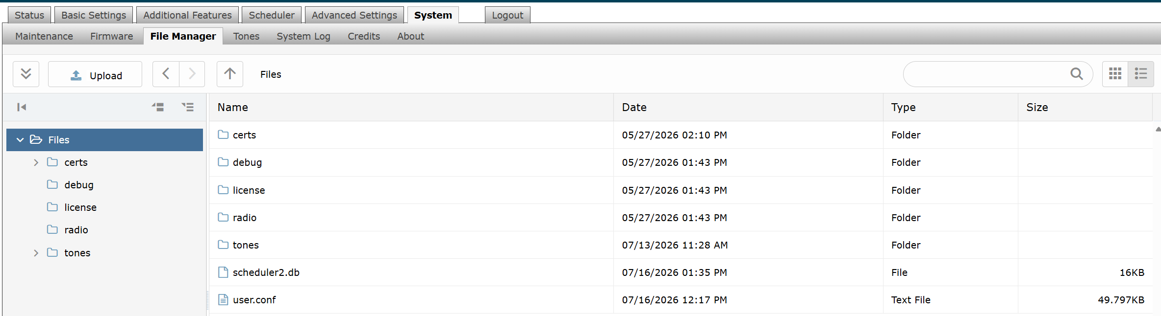
File Formats
When uploading files to the File Manager, refer to this table for supported file formats and requirements.
Folder | Supported Format | Requirements |
|---|---|---|
License | LIC | |
Tones | 8SVX, AIF, AIFC, AIFF, AIFFC, AL, AMB, AMR-NB, AMR-WB, ANB, AU, AVR, AWB, CAF, CDDA, CDR, CVS, CVSD, CVU, DAT, DVMS, F32, F4, F64, F8, FAP, FLAC, FSSD, GSM, GSRT, HCOM, HTK, IMA, IRCAM, LA, LPC, LPC10, LU, MAT, MAT4, MAT5, MAUD, MP2, MP3, NIST, OGG, PAF, PRC, PVF, RAW, S1, S16, S2, S24, S3, S32, S4, S8, SB, SD2, SDS, SF, SL, SLN, SMP, SND, SNDFILE, SNDR, SNDT, SOU, SOX, SPH, SW, TXW, U1, U16, U2, U24, U3, U32, U4, U8, UB, UL, UW, VMS, VOC, VORBIS, VOX, W64, WAV, WAVPCM, WV, WVE, XA, XI | Audio files must be in the following format:
|
Certs Folder
The certs folder stores trusted Certificate Authority (CA) certificates used when validating server certificates.
Upload additional certificates only if Validate Server Certificate is enabled under Advanced Settings → Advanced SIP.
To install a public CA certificate:
Obtain a Base64-encoded X.509 certificate (.pem, .cer, or .crt) from your Certificate Authority.
Go to System → File Manager.
Open the certs folder.
Click Upload.
Select the certificate file.
The certificate is added to the trusted certificate store.
For a list of pre-installed trusted certificates, contact support@algosolutions.com.
Debug Folder
The debug folder stores diagnostic files generated by the device.
Diagnostic files are used by Algo Technical Support to troubleshoot device issues.
To retrieve diagnostic files:
Go to System → File Manager.
Open the debug folder.
Download the requested diagnostic files.
Provide the files to Algo Technical Support.
License Folder
The license folder stores license files required to enable licensed features.
To install a license:
Obtain the license file from Algo.
Go to System → File Manager.
Open the license folder.
Click Upload.
Select the license (.lic) file.
The license is installed and becomes available after the upload completes.
Tones Folder
The tones folder stores custom audio files used for paging and notification applications.
To upload a custom audio file:
Go to System → File Manager.
Open the tones folder.
Click Upload.
Select the audio file from your computer.
Wait for the upload to complete.
The uploaded audio file is available for notification applications.
To replace an existing audio file:
Download the existing audio file.
Modify the file as required.
Save the modified file using a different file name.
Upload the new file to the tones folder.
Note
Audio files must meet the supported format and file requirements listed in File Formats.
Managing Tones
Tone files are used for ringing, alerts, and other audio notifications on the device. You can download the default Algo tone files, rebuild tone cache files if tones do not play correctly, and test tone files directly from the device interface.
Downloading Tone Files
Your device includes a set of default ring tones, stored in System → File Manager → Tones. If you delete any of these files, you can download them again to restore the original ring tones.
To download Algo default tone files:
Go to System → Tones.
Do one of the following:
To download the tone files and install them into your File Manager → Tones folder, select Download and Install.

To download them to your local disk, select the Algo website link.

Rebuilding Tone Cache Files
Rebuild Tone Cache Files recreates the cached versions of all tone files on the device. Use this option only if the tone cache is out of sync with the tone files, such as when uploaded or modified tones do not play correctly. The operation does not change or delete the original tone files and may take several minutes depending on the number and size of the files.
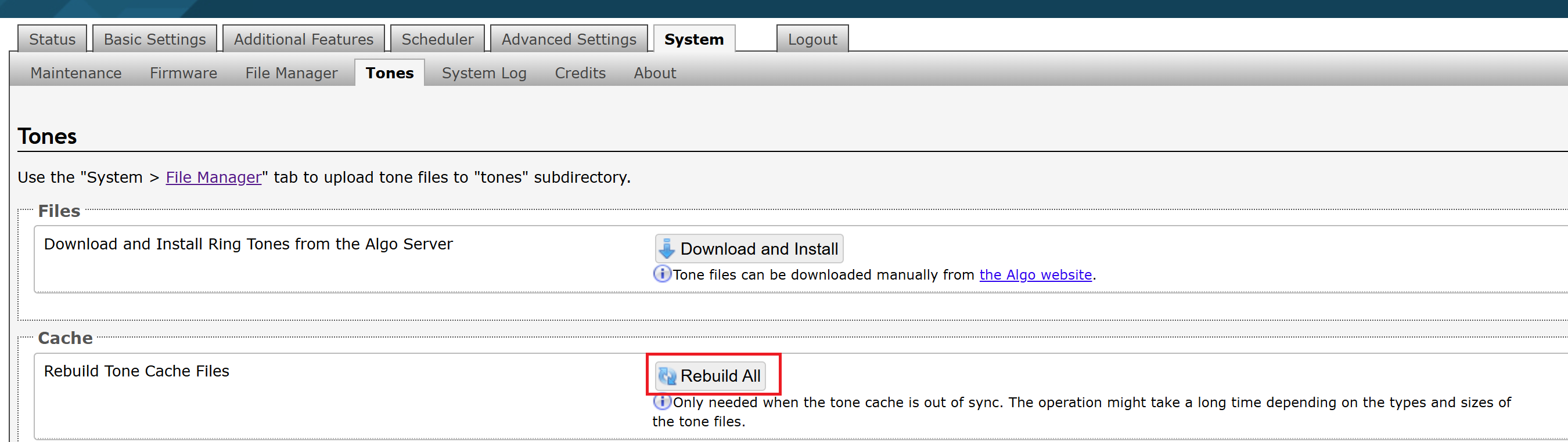
To rebuild tone cache files:
Go to System → Tones → Cache.
Select Rebuild All.
Appendix: Web Interface Reference
This section provides an overview of the pages and settings available in the 8211/8212 web interface. It describes the purpose of each configuration page to help you locate and configure the settings required for your deployment.
SIP Settings
The SIP tab under Basic Settings allows for the SIP server information and account credentials to be entered. This information can be obtained from your telephone system administrator or hosted account provider. After entering the information and saving the settings, go to the Status page to confirm the registration was successful.
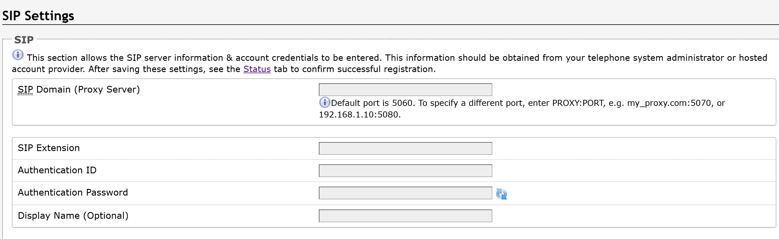
SIP | |
SIP Domain (Proxy Server) | The SIP Server's IP address (e.g., 192.168.1.111) or domain name (e.g., myserver.com). |
SIP Extension | Enter the SIP extension of the 8211/8212. |
Authentication ID | The Authentication ID is associated with the page extension. It is also referred to as ‘Username’ for some SIP servers. |
Authentication Password | This is the SIP password for the registered SIP account used to authenticate SIP users. |
Display Name (Optional) | Enter the name you want to display on the receiving device when you place a SIP call. For the display name to be shown, the PBX and phone(s) must be configured to display this message as the Caller ID. |
Features Settings
The Feature tab under Basic Settings allows you to configure the API password used to authenticate API requests to the target device, and to enable Peer-to-Peer calls.

Remote Device Settings | |
Remote Device RESTful API Password | When your device sends an API request to a device that requires authentication, enter the API password here. The password must match the RESTful API password configured on the target device. |
SIP Peer-To-Peer | |
SIP Peer-to-Peer | Enable this option to allow Peer-to-Peer SIP calls. SIP Peer-to-Peer allows your device to call other devices without SIP registration, or during a SIP server outage. |
Attempt Register | Disable Attempt Register so that peer-to-peer extensions can still receive calls, but your Algo device does not attempt to register or re-register those extensions with the SIP server. Excessive SIP REGISTER attempts may result in blacklisting by the SIP server. |
Multicast: Transmitter (Sender) Settings
The Multicast tab under Basic Settings allows you to configure your device to transmit multicast audio to compatible Algo IP endpoints, multicast-enabled IP phones, and supported Poly devices. You can configure the multicast type, zones, and Poly group paging settings.
Note
Always ensure that the multicast settings (such as zone numbers, the multicast IP address, and port definitions) on all receiver devices match those of the transmitter device.
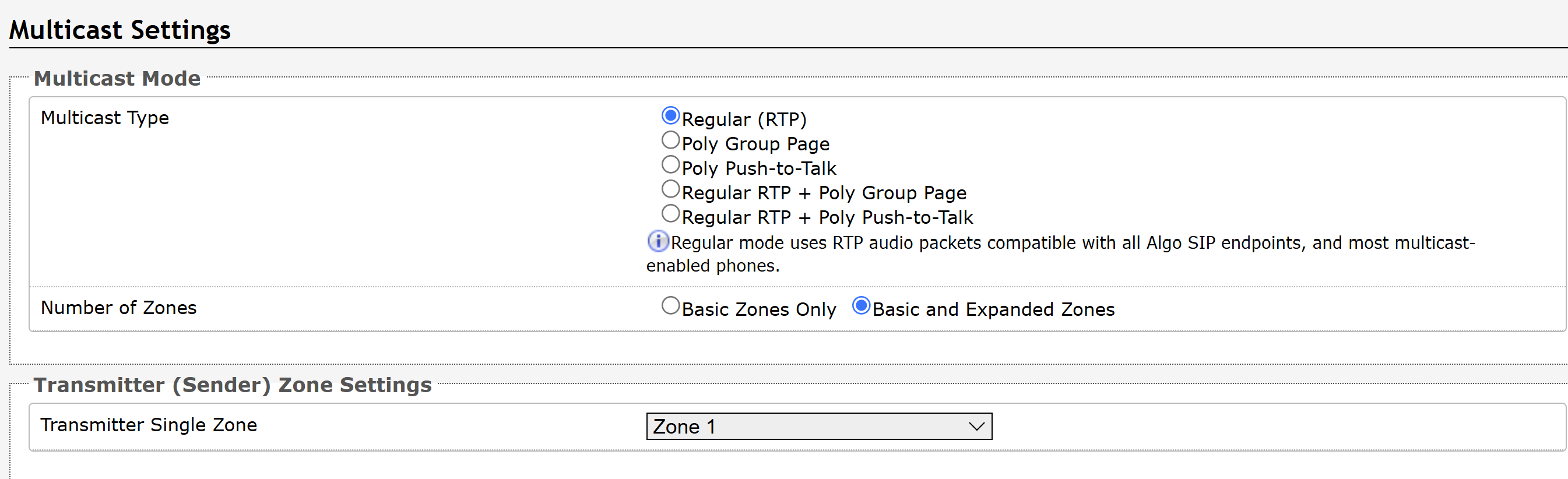
Multicast Mode | |
Multicast Type | The 8211/8212 may broadcast multicast paging compatible with Poly “on-premise group paging” protocol and most multicast-enabled phones that use RTP audio packets.
|
Number of Zones |
|
Poly Group Paging/Push-to-Talk This section is used if the Multicast Type includes Poly Group Page or Poly Push-to-Talk. | |
Poly Zone | Enter the same Multicast IP Address and Port number configured on the Poly phones. |
Poly Default Channel | Select the default group for the multicast stream to be sent to. |
Network Settings
The Network tab under Advanced Settings allows you to configure how the device connects to your IP network, including IP addressing (DHCP or static), DNS, and IPv4/IPv6 settings. These settings ensure the device can communicate with SIP servers, cloud services, and other network resources.
Note
Available settings may vary depending on your product model and firmware version.
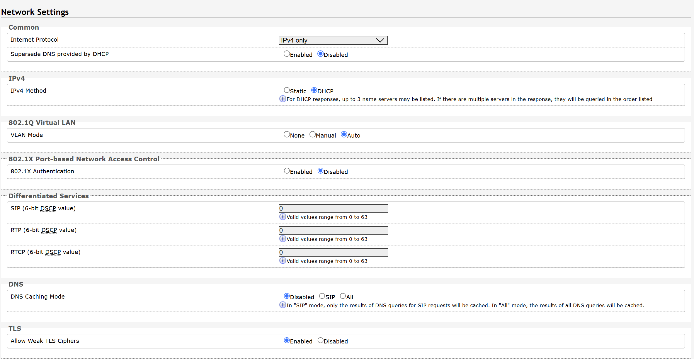
Common | |
Internet Protocol | Use the dropdown to select IPv4 Only or IPv4 and IPv6. |
Supersede DNS provided by DHCP | When enabled, this configuration allows DNS settings to be manually configured, replacing ones that may have been provided via DHCP. |
IPv4 | |
IPv4 Method |
|
IPv4 Address/Netmask | Enter the static IP address and netmask (CIDR format) for the device (e.g., 192.168.1.23/24 where “/24” is equivalent to a netmask of 255.255.255.0). |
IPv4 Gateway | Enter the gateway address. |
IPv6 | |
IPv6 Method | The device can be set to a static or DHCP IP address. |
IPv6 Address/Netmask | Enter the static IP address and netmask (CIDR format) for the device (e.g., 2001:123::abcd:1234/64). |
IPv6 Gateway | Enter the gateway address. |
ICMPv6 Options | |
Destination Unreachable Messages | Enable to restrict traffic by filtering ICMPv6 packets. |
Neighbor Discovery Redirect Messages | Enable to restrict traffic by filtering ICMPv6 packets. |
Anycast Echo Replies | Enable to restrict traffic by filtering ICMPv6 packets. |
Enable Rate Limiting Outbound Messages | Enable to limit the device to respond to other network devices at the specified rate below and prevent it from receiving multiple requests at the same time. |
Rate Limit (packets per second) | Specify the packets per second allowed for Rate Limiting Outbound Messages. |
802.1Q Virtual LAN If the device is using VLAN, you will need to be on the same VLAN to access the web interface, unless routing has been configured between VLANs. | |
VLAN Mode | None: Disable VLAN. Manual: Configure a VLAN by specifying its ID and frame priority. Auto: Detect VLAN information automatically and tag outgoing traffic accordingly. |
VLAN ID | Specify the VLAN that the Ethernet frame belongs to. The hexadecimal values 0x000 and 0xFFF are reserved. All other values may be used as VLAN identifiers, allowing up to 4094 VLANs. |
VLAN Priority | Set the frame priority level. Otherwise known as Priority Code Point (PCP), VLAN Priority is a 3-bit field that refers to the IEEE 802.1p priority or frame priority level. Values are from 0 (lowest) to 7 (highest). |
802.1X Port-based Network Access Control | |
802.1x Authentication | Enable to add credentials to access LAN or WLAN that have 802.1X network access control (NAC). You can ask your IT Administrator for this information. |
Authentication Mode | Select the desired authentication mode. |
Anonymous ID | If configured, the device will send the anonymous ID to the authenticator instead of the 802.1X client username. |
ID | The ID should contain a string identifying the IEEE 802.1X authenticator originating the request. Ask your IT Administrator for details. |
Password | Ask your IT Administrator for details. |
Validate Server Certificate | Enable to validate the authentication server against common authorities. To validate additional certificates, go to the System → File Manager to upload a Base64 encoded X.509 certificate file in .pem, .cer, or .crt format to the certs folder. |
Differentiated Services | |
SIP (6-bit DSCP value) | Enter the Differentiated Services Code Point (DSCP) value for SIP packets. |
RTP (6-bit DSCP value) | Enter the DSCP value for RTP packets. |
RTCP (6-bit DSCP value) | Enter the DSCP value for RTCP packets. |
DNS | |
DNS Caching Mode | There are three mode options:
|
TLS | |
Allow Weak TLS Ciphers | Enables compatibility with legacy systems that may not support the most current encryptions standards. |
Admin Settings
The Admin tab under Advanced Settings allows you to configure device access, security, management, monitoring, and integration features.
From this page, you can change administrator credentials, manage logging and network management settings, enable APIs and external services, and configure device maintenance options.
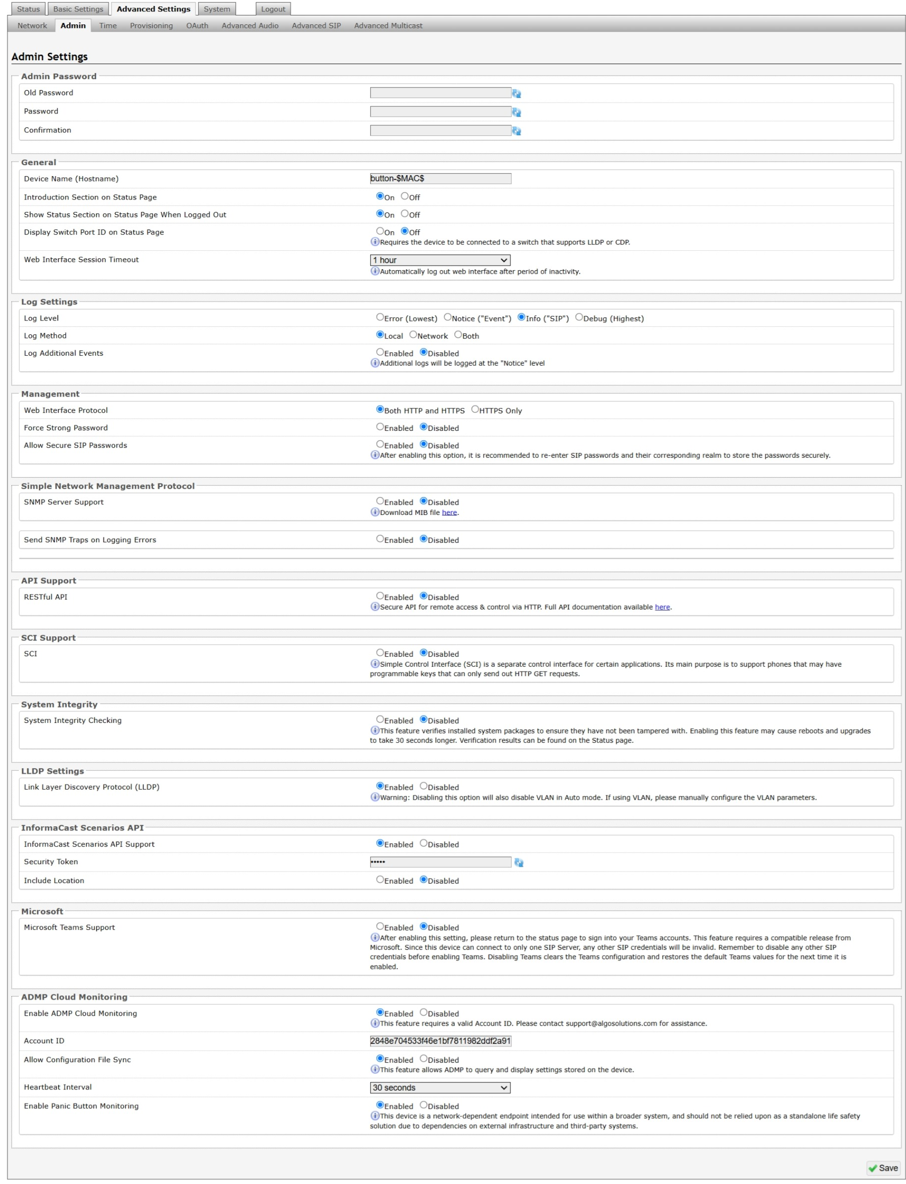
Admin Password | |
Old Password | Enter the old admin password. The default password when you first get the device is algo. |
Password | Enter a new admin password to log into the device web interface. Make sure the new password is stored safely. If the password is forgotten, you must reset the device entirely to restore the default password. All other settings will be reset to the original default settings as well. To reset the device using the button, see Restoring Factory Default Settings Only. |
Confirmation | Re-enter your new admin password. |
General | |
Device Name (Hostname) | Add a name to identify the device. |
Introduction Section on Status Page | Select On to show the introduction text on the login screen. |
Show Status Section on Status Page when Logged Out | Select On to allow others to view the status page without logging in. Select Off to hide the settings and configurations on the status page unless a user is logged in to ensure only trusted users can view device information. |
Display Switch Port ID on Status Page | Select On to display the Switch Port ID on the Status Page. This option is only possible if the device is connected to a switch that supports LLDP or CDP. |
Web Interface Session Timeout | Set the maximum duration of inactivity to log a user out of the web interface automatically. |
Log Settings | |
Log Level | Select the types of information you want to include in the system log files.
|
Log Method | Select a log method: Local: The log file is saved in RAM on the device. Network: Send the log file to an external SysLog server so settings are not lost if the device is rebooted, or for ease of central access. Both: Use both methods. |
Network Log Protocol | Select the transport protocol used to send Syslog messages to the configured log server. |
Log Server | Enter the Syslog server address provided by your IT administrator. |
Log Additional Log Events | To be used by support@algosolutions.com if necessary. |
Management | |
Web Interface Protocol | HTTPS is always enabled on the device. HTTP is enabled by default but may be disabled. To do so, select HTTPS Only mode so requests are automatically redirected to HTTPS.
|
Force Strong Password | When Enabled, you can enforce a secure password for the device web interface for additional protection. The password requirements for a strong password are:
|
Allow Secure SIP Passwords | When Enabled, SIP passwords are stored in the configuration file in an encrypted format to prevent viewing and recovery. If enabled, navigate to Basic Settings → SIP and fill out the Realm field. To obtain your SIP Realm information, contact your SIP Server administrator or check the SIP log file for a registration attempt. The Realms may be the same or different for all the extensions used. All the configured Authentication Password(s) must be re-entered here as well as any other locations where SIP extensions have been configured to save the encrypted password(s). If the Realm is changed later, all passwords must be re-entered to save the passwords with the new encryption. |
Simple Network Management Protocol | |
SNMP Support | Disabled by default. The existing setting will respond to a simple status query for automated supervision. |
Send SNMP Traps on Logging Errors | When enabled, the device sends unsolicited SNMP trap notifications when logging errors occur. |
SNMP Community String | Speak to your IT Administrator for more information. |
SNMPv3 Security | Speak to your IT Administrator for more information. |
API Support | |
RESTful API | Disabled by default. Enable a secure API for remote access and device control via HTTP. For more information, see Algo RESTful API Guide. |
Authentication Method | Select an option:
|
RESTful API Password | Authentication requires generating a valid HMAC signature using the provided RESTful API Password. The device verifies this signature before processing your API command. For more information, see the Algo RESTful API Guide or speak to your IT Administrator. |
SCI Support | |
SCI | Disabled by default. Simple Control Interface (SCI) is a separate control interface for certain applications. Its primary purpose is to support phones that may have programmable keys that can only send out HTTP GET requests and allow them to initiate events remotely on an Algo device. |
SCI Password | Enter your SCI password. |
System Integrity | |
System Integrity Checking | Enable this feature to verify that installed system packages have not been tampered with by running a check. Enabling this feature may cause reboots and upgrades to take 30 seconds longer. Verification results can be found on the Status page. |
LLDP Settings | |
Link Layer Discovery Protocol (LLDP) | Enables LLDP to exchange network configuration information with the connected network switch. |
Note
Disabling Link Layer Discovery Protocol (LLDP) prevents your device from exchanging network configuration information with the connected network switch. If you are using a VLAN, make sure Link Layer Discovery Protocol (LLDP) is enabled, or that the VLAN Mode (under Advanced Settings → Network Settings) is set to Manual so you can configuration VLAN settings manually.
InformaCast Scenarios API | |
InformaCast Scenario API Support | Enable the device to start an InformaCast Scenario via relay input. This feature can work without an InformaCast license, as only the output device requires a license. |
Security Token | Enter the Security Token used for authenticating API requests with the InformaCast system. |
Include Location | Enable this option to include the device’s location in the scenario trigger request. |
Microsoft | |
Microsoft Teams Support | Enable to allow the device to register with a Microsoft Teams account. The device reboot will take up to 5 minutes to complete, as the device will communicate several times with the Microsoft server. This feature requires a compatible release from Microsoft. After enabling this setting, please return to the Status page to sign into your Teams accounts. This feature requires a compatible release from Microsoft. For more details, please see the Microsoft Teams Configuration Guide. |
ADMP Cloud Monitoring | |
Enable ADMP Cloud Monitoring | The Algo Device Management Platform (ADMP) simplifies the process of managing, monitoring, and maintaining Algo devices from any location. This feature requires a valid Account ID. To learn more about ADMP and how to purchase a license, visit the ADMP webpage. |
Account ID | Enter the account ID listed on the Settings page of your ADMP account. |
Allow Configuration File Sync | Enable ADMP to query and display settings stored on the device. |
Heartbeat Interval | Select how often ADMP should check the status of your device. |
Enable Panic Button Monitoring | Enable to monitor Panic Button status in ADMP, including:
|
Time Settings
Time configures the device's date, time, time zone, and Network Time Protocol (NTP) settings to ensure accurate timekeeping and proper scheduling of time-based features.
Network time is used for logging events into memory for troubleshooting.
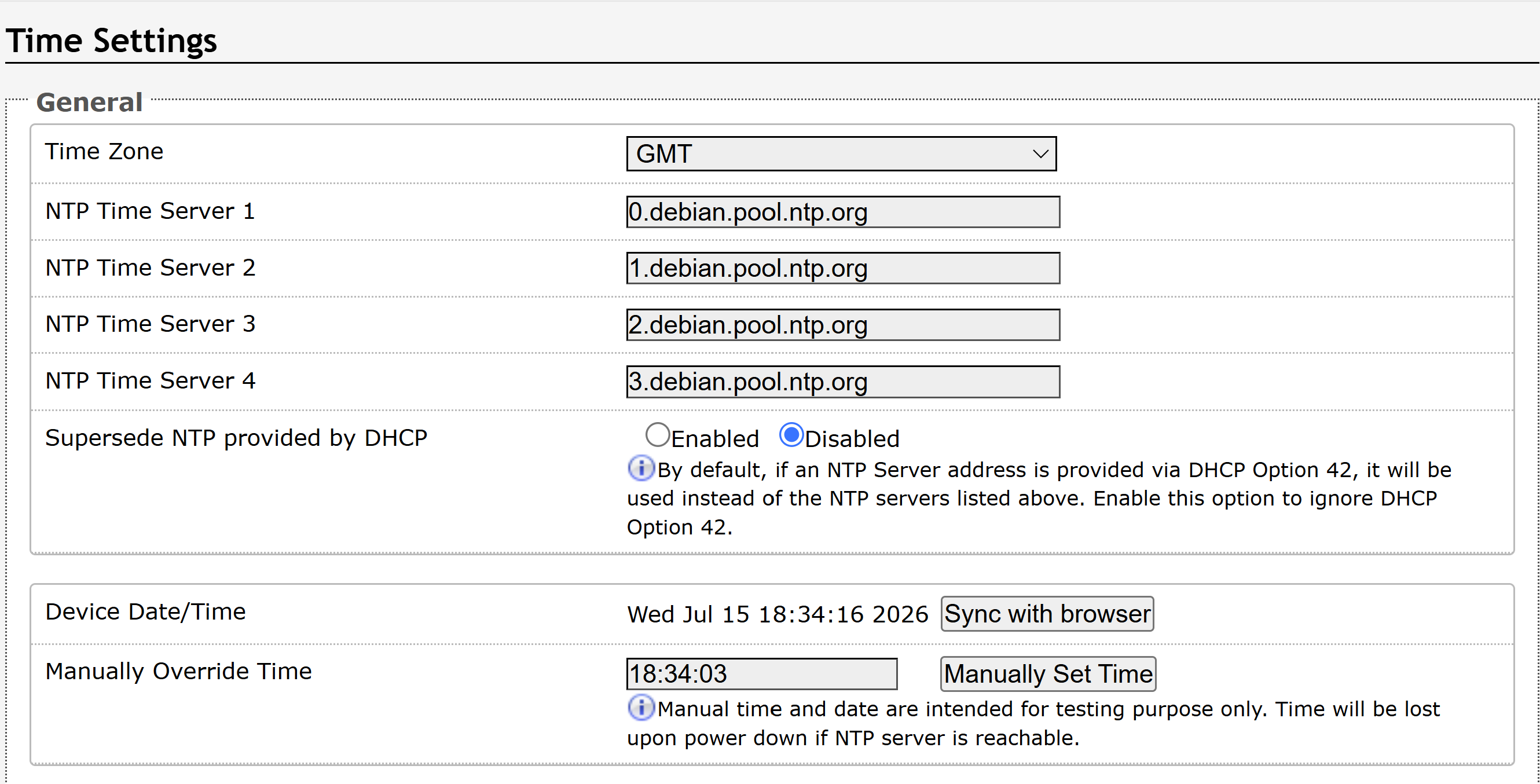
Time Settings | |
Time Zone | Use the dropdown to select the time zone required for your device. |
NTP Time Server | The interface will attempt to use Time Server 1 and work down the list if one or more of the time servers become unresponsive. These settings are pre-populated with public NTP servers hosted on the internet. To use these, the device requires an internet connection. Alternatively, this can be customized to point the device to any other NTP server hosted or premise-based. |
Supersede NTP provided by DHCP | By default, if an NTP Server address is provided via DHCP Option 42, it will be used instead of the NTP servers listed above. Enable this option to ignore DHCP Option 42. |
NTP Symmetric Key Authentication | To enable, create a new folder in the tab System → File Manager and create a folder named ntp. Upload the symmetric key file and rename the file to ntp.keys. |
Device Date/Time | This field shows the current time and date set on the device. If you are testing the device on a lab network that does not have access to an external NTP server, click Sync with browser to temporarily set the time on the device. This time value will be lost at power down or overwritten if a connection to the NTP server is available. Time and date are used for logging purposes. |
Manually Override Time | Manual time and date are intended for testing purposes only. Time will be lost upon power down if the NTP server is reachable. |
Provisioning Settings
Provisioning configures automatic device provisioning, allowing the device to retrieve configuration files and updates from a remote provisioning server.
For more information, see Central Provisioning of Algo IP Endpoints.
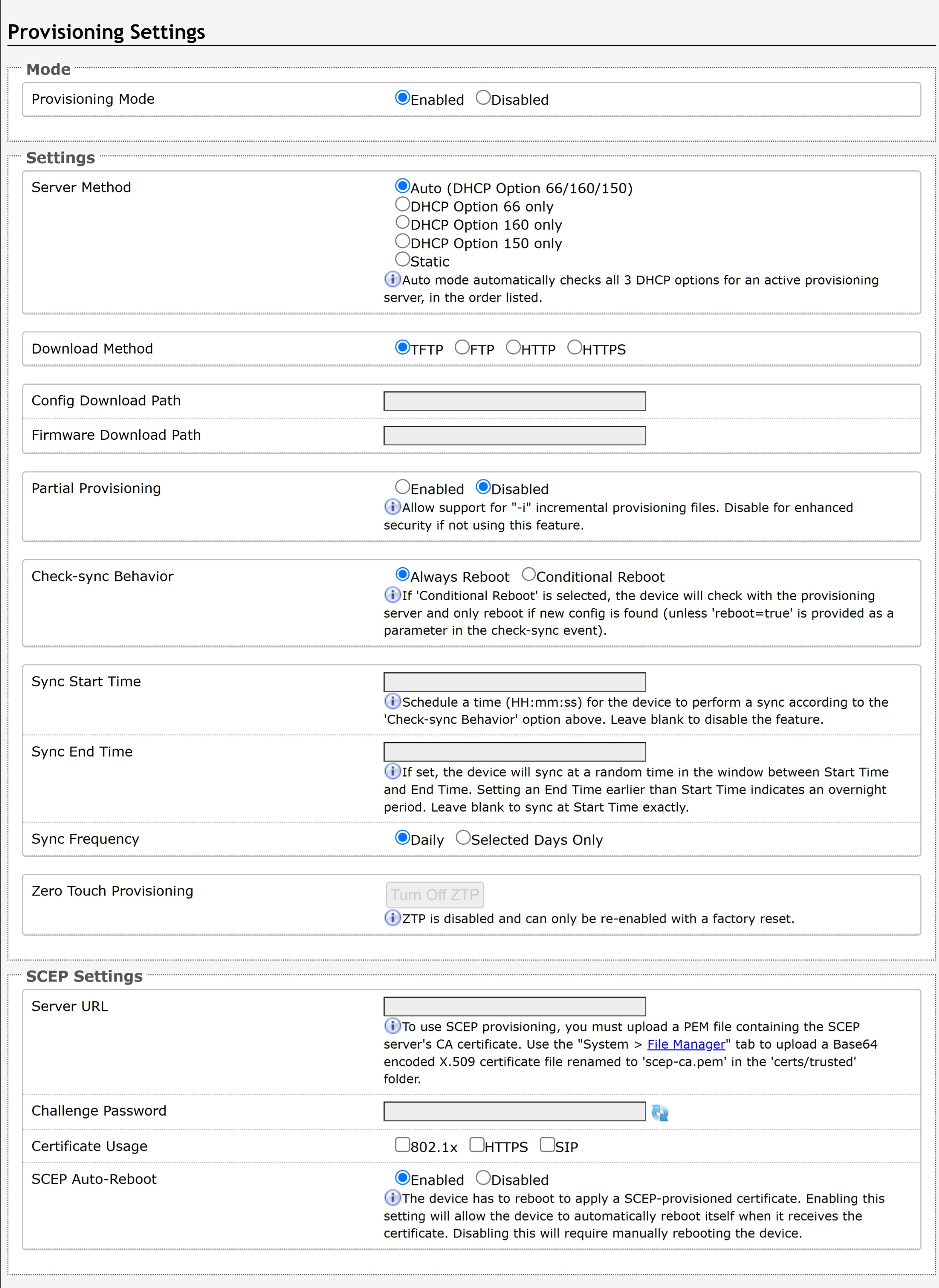
Note
It is recommended that Provisioning Mode be set to Disabled if this feature is not in use. This will prevent unauthorized re-configuration of the device if DHCP is used.
Mode | |
Provisioning Mode | Enabling provisioning allows installers to pre-configure the device on a network before installation. This is typically done for large deployments to save time and ensure consistent setups. |
Settings | |
Server Method | Set to Auto by default. Select a Server Method.
For provisioning to work with a DHCP option, DHCP must be enabled under Advanced Settings → Network → IPv4. |
Static Server | Enter the server address or domain. |
Download Method | Select your preferred method for downloading provisioning files. The options are:
The device configuration files can be automatically downloaded from a provisioning server using DHCP Option 66. This option code (when set) supplies a TFTP boot server address to the DHCP client to boot from.
Both protocol and path are supported for Option 66, allowing for http://myserver.com/config-path to be used. |
Config Download Path | Enter the path where the configuration file is located in the provisioning server. |
Firmware Download Path | Enter the path where the firmware file is located in the provisioning server. |
Partial Provisioning | Enable to allow support for “-i” incremental provisioning files. Disable for enhanced security if this is not required. |
Check-sync Behavior | Select Always Reboot to set the device to always reboot despite other settings. |
Sync Start Time | Set a time (HH:MM:SS) for the device to perform a sync according to the Check-sync Behavior setting. Leave this blank if not needed. |
Sync End Time | If set, the device will sync randomly in the window between Sync Start Time and Sync End Time. Setting an End Time earlier than the Start Time indicates an overnight period. Leave blank to sync exactly at the set start time. |
Sync Frequency | Select the sync frequency. Frequency can be set to Daily or Selected Days Only. |
Sync Days | Select the days of the week for syncs to occur. |
Zero Touch Provisioning | ZTP is enabled by default, allowing the device to automatically fetch its configuration on first boot from the provisioning server.
|
SCEP Settings | |
Server URL | Enter the URL of the Simple Certificate Enrollment Protocol (SCEP) server used to provision certificates to the device. The SCEP server's CA certificate must be uploaded to the device before using SCEP provisioning.
|
Challenge Password | Enter the challenge password used to authenticate the device's certificate enrollment request with the SCEP server. |
Certificate Usage | Select where the SCEP-provisioned certificate will be used: 802.1x, HTTPS, SIP, or a combination of these services. |
SCEP Auto-Reboot | Enable to automatically reboot the device after it receives a SCEP-provisioned certificate. A reboot is required to apply the certificate. If disabled, the device must be rebooted manually. |
Advanced Audio Settings
Advanced Audio allows your device to send audio packets at all times.

Functions | |
Always Send RTP Media | Enable to send audio packets at all times, even during one-way paging mode. This option is needed when the server expects to always see audio packets. |
Advanced SIP Settings
Advanced SIP configures advanced SIP communication settings, such as registration, session timers, transport, codecs, and other protocol options to optimize interoperability and call performance.
General | |
SIP Transportation | Select a transport layer protocol to use for SIP messages from the dropdown. These options include:
|
SIPS Scheme | Only visible when SIP Transportation is set to TLS. Enable to require the SIP connection from endpoint to endpoint to be secure. |
Validate Server Certificate | Enable validation of the SIP server against common certificate authorities. To validate additional certificates, navigate to System → File Manager to upload a Base64 encoded X.509 certificate file in .pem, .cer, or .crt format to the certs folder. |
SIP Outbound Support (RFC 5626) | Enable this option to support best networking practices according to RFC 5626. This option should be enabled if the device is registered with a hosted server or TLS is used for SIP Transportation.
|
Outbound Proxy | Enter the IP address for an outbound proxy. |
Register Period (seconds) | Enter the maximum requested period that the device will re-register with the SIP server. The default setting is 3600 seconds (1 hour).
|
Rate Limit SIP Registration | This option should be used in cases where many SIP extensions are registered (ex. one for each zone). Select a rate limit to stagger registration requests and prevent overloading the server by sending them all at the same time. |
Wait for Successful Unregister | Enable to wait for the device to successfully unregister from the server. Enabling may cause a slight delay during configuration changes and reboots. |
SRTP | |
SDP SRTP Offer | Select an option from the dropdown menu:
|
SDP SRTP Offer Crypto Suite | The encryption and authentication algorithms are used for voice data. |
NAT | |
Media NAT | None: Disable NAT. ICE: Enable advanced NAT support. STUN: Enable basic NAT support. |
TURN Server | Enter the IP address or domain of the ICE server. |
TURN User | Enter the username of the ICE server. |
TURN Password | Enter the password of the ICE server. |
STUN - Server | Enter the IP address or domain of the STUN server. |
Server Redundancy | |
Server Redundancy Feature | Enable to configure up to two secondary backup SIP servers. When enabled, the device will attempt to register with the primary server but switch to a secondary server when necessary. The configuration allows re-registration to the primary server upon availability or to stay with a server until unresponsive. |
Backup Server #1, #2 | Provided by your SIP provider or IT team. |
Polling Intervals (seconds) | Select the time interval for sending monitoring packets to each server from the dropdown menu. Inactive servers are always polled and the active server may optionally be polled. |
Poll Active Server | Enable to explicitly poll the current server to monitor availability. Other regular events may also handle this automatically and can be disabled to reduce network traffic. |
Automatic Fallback | Enable to allow the device to reconnect with a higher priority server once available, even if the backup connection is still working. |
Polling Method | Select a polling method based on what your SIP provider supports. |
Zoom Phone Local Survivability | |
|---|---|
Local Survivability | Enable re-registration with the local Zoom Phone Local Survivability (ZPLS) Node if connection to Zoom fails. This allows sites to maintain a subset of Zoom Phone features even if connectivity to the Zoom Phone cloud is lost.
|
Survivability Proxy | Enter the IP address or domain name of the local Zoom Phone Local Survivability (ZPLS) node. |
Interoperability | |
Keep-Alive Method | Select a keep-alive method:
|
Keep-Alive Interval (seconds) | Set the interval in seconds that the CRLF message should be sent. 30 seconds is recommended. |
Use Outgoing TLS port in SIP Headers | Enable to use of the ephemeral port number from an outgoing SIP TLS connection instead of the listening port number in SIP Contact and Via headers. This is useful for connecting the device to some local SIP servers, such as Asterisk or FreeSWITCH. |
Do Not Reuse Authorization Headers | Enable so all SIP authorization information from the last successful request will not be reused in the next request. |
Allow Missing Subscription-State Headers | Enable to allow SIP NOTIFY messages that do not contain a ‘Subscription-State’ header. |
Add MAC in SIP User Agent Header | Specifies whether to include the device’s MAC address in the SIP |
Advanced Multicast Settings
These settings are only visible when in Transmitter or Receiver multicast mode. This can be set in Basic Settings → Multicast. The default pre-populated multicast zone IP addresses and ports will work in most cases and should only be altered for rare cases.
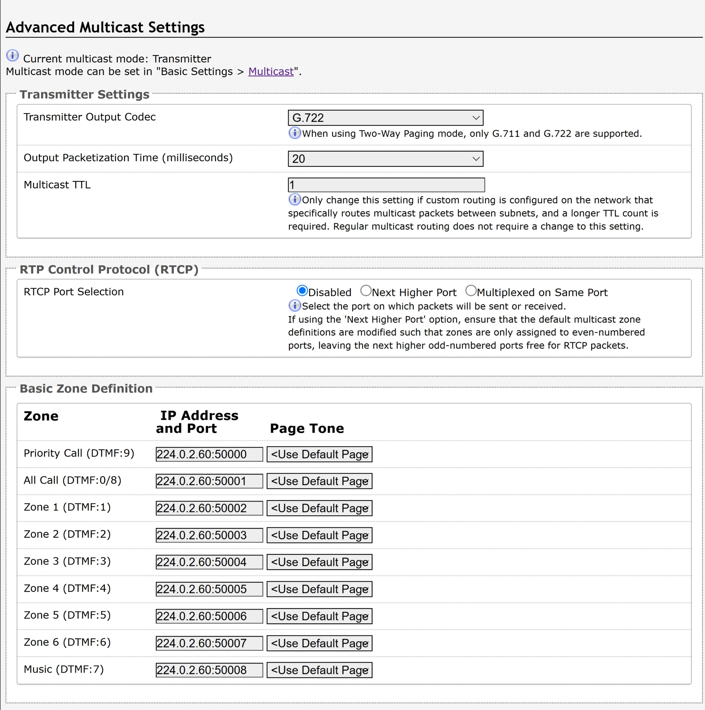
Transmitter Settings | |
Transmitter Output Codec | Select an audio encoding format for the Transmitter device to use when sending output to the Receivers. Supported formats include:
|
Output Packetization Time (milliseconds) | Select the size of the audio packets the Transmitter sends to the Receivers from the dropdown menu. The default of 20 milliseconds is recommended unless a different value is specifically required for compatibility with other devices. |
Multicast TTL | Only change the multicast time to live (TTL) setting if custom routing is configured on the network that specifically routes multicast packets between subnets and a longer TTL count is required. This ensures packets are not bounced back and forth in a network indefinitely. When the TTL is reached, the router drops the packet. |
RTP Control Protocol (RTCP) | |
RTCP Port Selection | Select how a port will be chosen to send or receive RTCP packets.
|
Appendix: Compliance and Safety
Product Warnings
Important Notice
This product is powered by a certified limited power source (LPS), Power over Ethernet (PoE); through CAT5 or CAT6 connection wiring to an IEEE 802.3at- or 802.3af-compliant network PoE switch. The product is intended for installation indoors. If the product is installed beyond the building perimeter or used in an inter-building application, the wiring connections must be protected against overvoltage/transient. Algo recommends that this product is installed by a qualified electrician.
If you are unable to understand the English language safety information then please contact Algo by email for assistance before attempting an installation support@algosolutions.com.
Emergency Communication
If used in an emergency communication application, the 8211/8212 should be routinely tested. SNMP or ADMP supervision is recommended for assurance of proper operation. Contact Algo for other methods of operational assurance including the use of the integrated microphone for automated “sound to air” acoustic testing.