Disclaimer
The information contained in this document is believed to be accurate in all respects but is not warranted by Algo. The information is subject to change without notice and should not be construed in any way as a commitment by Algo or any of its affiliates or subsidiaries. Algo and its affiliates and subsidiaries assume no responsibility for any errors or omissions in this document. Revisions of this document or new editions of it may be issued to incorporate such changes. Algo assumes no liability for damages or claims resulting from any use of this manual or such products, software, firmware, and/or hardware.
No part of this document can be reproduced or transmitted in any form or by any means – electronic or mechanical – for any purpose without written permission from Algo.
For additional information or technical assistance in North America, please contact Algo’s support team:
1-604-454-3792
About
The Algo 1211 Single Button and Algo 1212 Dual Button are smart relay accessory buttons that connect to compatible Algo IP Endpoints. The 1211 Single Button contains one button and the 1212 contains two buttons. Each button supports two separate configurable actions—press and long press—giving the 1211 a total of two configurable actions and the 1212 a total of four.
When a button is pressed, the host Algo IP Endpoint performs the configured action, such as playing a tone, making a two-way SIP call, or sending API requests.
The 1211 and 1212 buttons are designed to be customized for each deployment's specific needs, featuring configurable multi-color illuminated button(s), selectable faceplate labels for unique colors and text, and optional protective cover(s) to prevent unintentional button presses.
The 1211 and 1212 buttons connect to the Relay Input port of the host Algo IP Endpoint. While this port can detect a typical dry contact closure, the Endpoint’s electronic circuitry can also provide power, configuration, and control to the buttons. This enables smart actions, supervision, and cloud connectivity that are not normally achievable with a non-IP solution. As a result, the 1211 and 1212 buttons only function when deployed with a compatible Algo IP Endpoint.
Installation
Note
Install the 1211/1212 and test functionality before applying the faceplate label. This label covers the mounting screws and is difficult to remove once applied.
This product is designed for indoor dry environments only.
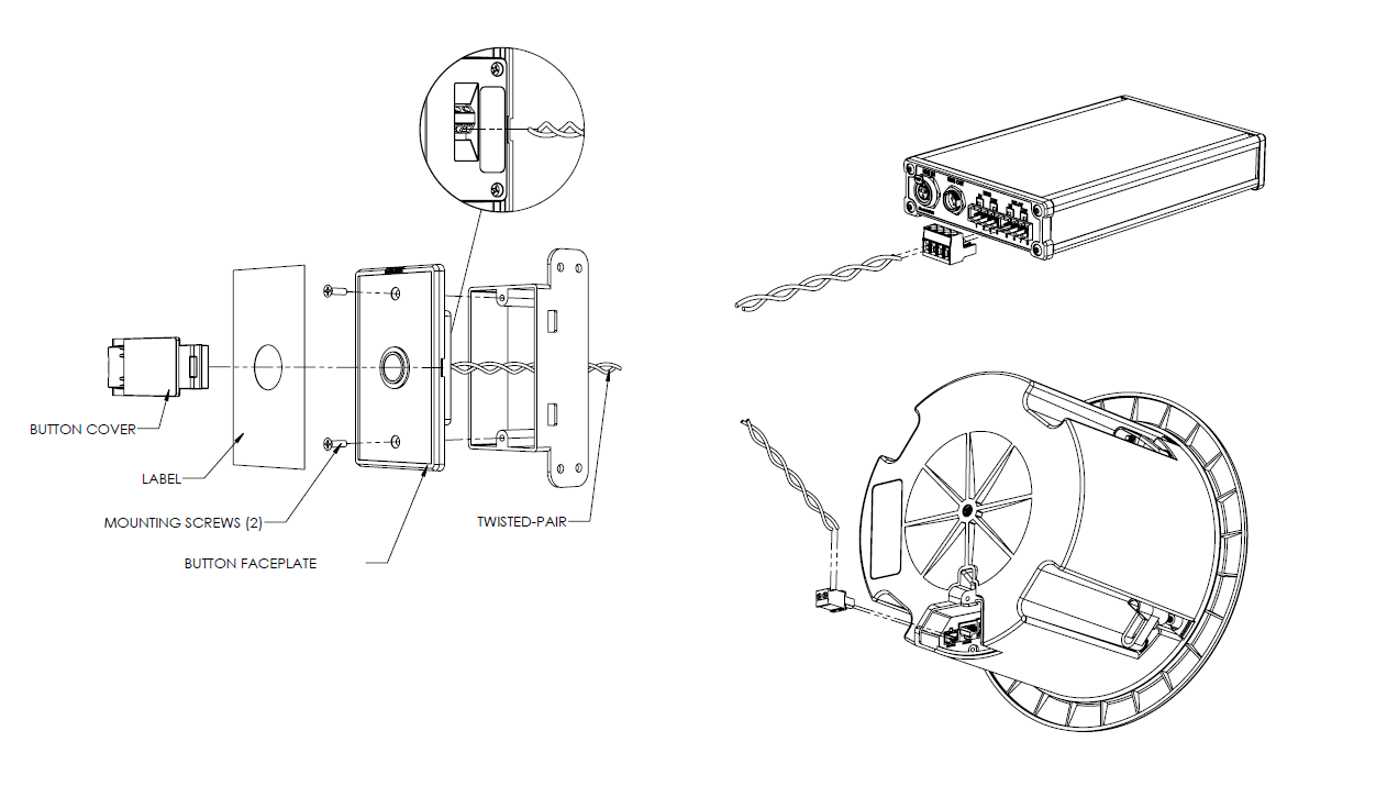
Connect a single twisted-pair cable (24 AWG) to the terminal block of the 1211/1212. The connection is polarity-independent.
Feed the single twisted-pair cable through a single-gang box or low-voltage bracket (not included) and connect it to the Relay Input of a compatible Algo IP Endpoint. The 1211/1212 can be installed with wiring up to 1000 feet (300 m) in length from the Algo IP Endpoint.
Attach the 1211/1212 to a single-gang box or low-voltage bracket using the provided flat-head screws.
Ensure the end with the Algo logo is at the top.
Verify the 1211/1212 connection:
Log in to the Algo IP Endpoint's web interface.
The Endpoint must be on firmware v5.7 or later.
Go to Additional Features → Input/Output.
Set Relay Input Mode to Algo 1211 Single Button or Algo 1212 Dual Button.
Select Save.
Once the host Endpoint is configured for the Algo 1211 Single Button/Algo 1212 Dual Button, the button(s) on the 1211/1212 will illuminate steady blue.
Note
Do not attach the faceplate label until functional testing is complete. Refer to the Getting Started section for more details.
Select the preferred faceplate label. Peel off the adhesive backing from the faceplate label and apply it to the 1211/1212 button. Ensure the label is aligned to the edge of the label indent to ensure a proper fit. After positioning the label, apply firm, even pressure across the entire surface, including the edges and corners, to ensure proper adhesion and a long-lasting bond.
If customized product labels are required, please contact Algo Support (support@algosolutions.com).
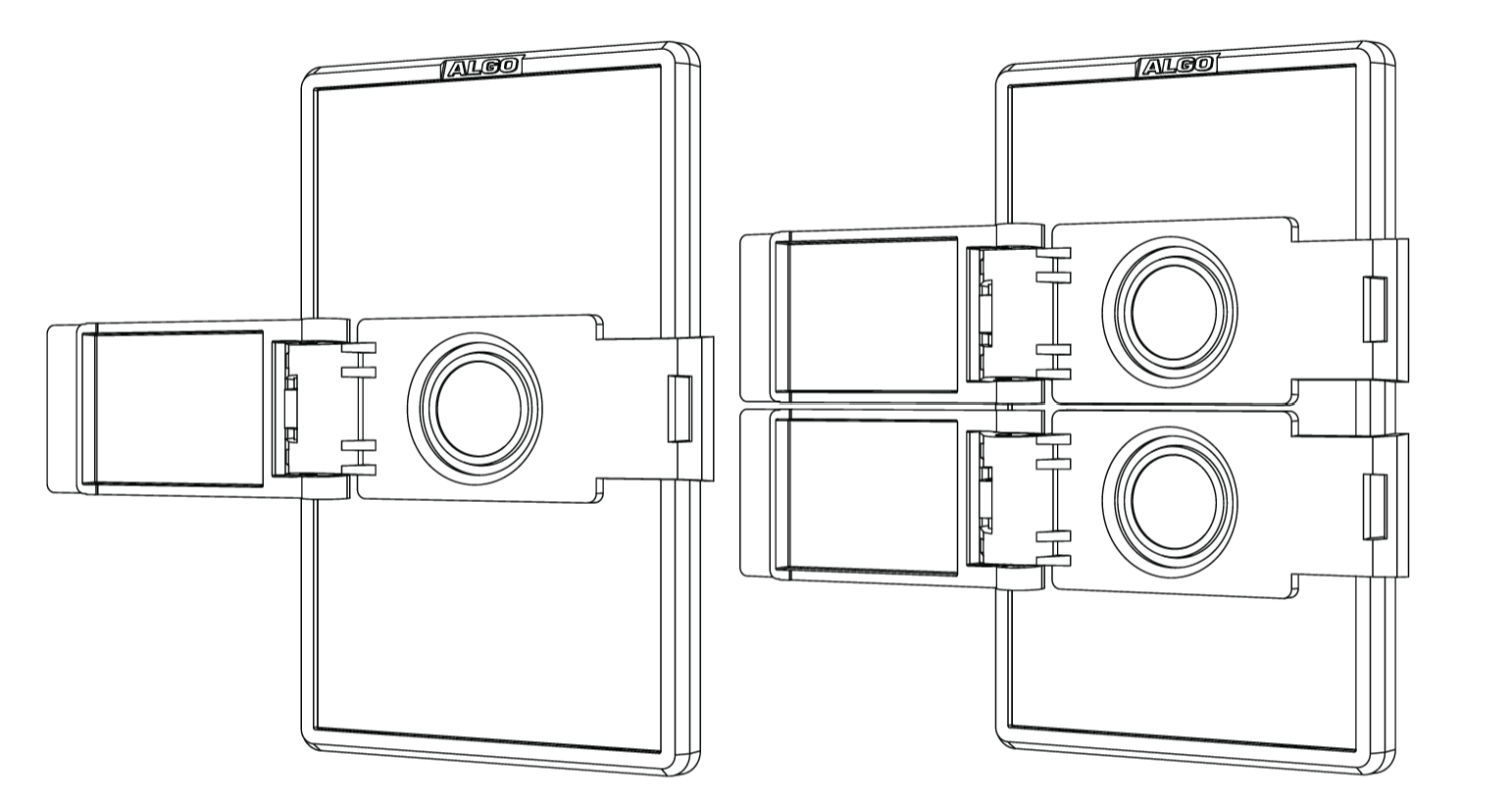
(Optional) Install the button cover by aligning it with the slots on the outside edges of the faceplate, then press down firmly along the left and right edges until the button cover snaps into place.
Note
If the button cover(s) need to be removed, insert a small screwdriver into the slot on the hinge side of the button cover to pry the cover snap away from the faceplate.
Assembling the Button Cover
The button cover consists of two pieces (Hinge Receiver and Hinge Pin) and is pre-assembled. In case you need to assemble it yourself, follow this procedure.
To assemble the button cover:
Place the Button Frame (the piece with the circular hole) with the curved ends facing upward. Position the Button Cover so the recessed side faces downward.
Insert the hinge-channel end of the Button Frame into the opening of the Button Cover, then align the axle with the two short guide channels.
Hold the two pieces at approximately 90 degrees to each other, then press both ends of the axle on the Button Cover piece until it snaps fully into the guide channels on the Button Frame.
Open and close the Button Cover to verify smooth movement and proper alignment.
Getting Started
Log in to the web interface of the host Algo IP Endpoint.
The Endpoint must be on firmware v5.7 or later.
Go to Additional Features → Input/Output.
Set Relay Input Mode to Algo 1211 Single Button or Algo 1212 Dual Button.
Configure an Action for the button Press or Long Press.
Depending on the host Endpoint model, available actions may include:
Play Tone: Plays a recorded audio file to a local speaker and multicasts it (if configured).
Make SIP Voice Call: Initiates a two-way voice call.
Make SIP Call with Tone: Makes a SIP call to a pre-configured SIP extension and plays a recorded audio file.
Send API Request: Sends up to five API requests to other devices.
Send SNMP Trap: Sends a status alert to a network monitoring system.
Stream Mic Audio:
All Endpoints except 8301: Streams microphone audio to multicast only (requires Transmitter multicast mode enabled).
8301: Plays sound on the Line Out and Aux Out ports as well as multicast (if configured). The desired audio input port may be selected.
Cancel Action: Cancels the current action.
For 1212, you can configure each button action independently.
Select Save.
Configuring the Button
After you connect the Algo 1211 Single Button or 1212 Dual Button to its host IP endpoint, you can:
Note
Your host Algo IP endpoint must be on firmware version 5.7 or later.
Configuring the Button Ring Illumination Behavior
You can customize the LED-illuminated button rings to indicate the status of the host endpoint, including:
Idle: The host device has no active activities.
Ringing SIP Call: The host device is making a SIP call.
Active SIP Call: The host device has an ongoing SIP call.
Activated: The host device is activated for a non-SIP call activity (e.g., multicasting, tone playing, sending API calls or SNMP trap messages).
 (1).png)
To configure the button ring illumination behavior:
Log in to the host Algo endpoint’s web interface.
Do one of the following:
(All other products) Go to Additional Features → Input/Output.
Set Relay Input Mode to Algo 1211 Single Button or Algo 1212 Dual Button.
(8063) Go to Basic Settings → Basic Config → Inputs.
Select the desired Input and set it to Audio Broadcast Feature or Other Features.
Set Input Type to Algo 1211 Single Button or Algo 1212 Dual Button.
Go to the Button Appearance section.
Configure the following for each status:
Brightness: Choose from Off, Low, Medium, or High.
Color: Choose from Blue, Red, Green, or Amber.
Pattern:
Steady: Illumination remains on.
Slow Flash: Illumination flashes slowly.
Fast Flash: Illumination flashes rapidly.
Alarm: Illumination flashes twice per cycle.
Set Minimum Activated State Time (seconds).
This setting defines the minimum amount of time the Activated illumination remains visible for non-SIP activities. It provides visible feedback even when an action, such as an API request, completes very quickly.
Select Save.
Trigger the configured button actions and verify that the ring indicates the expected states.
Note
If a SIP call cannot be established, for example because the destination is busy, the button ring uses the Alarm pattern to provide visual feedback that the call attempt was unsuccessful.
Configuring and Triggering Button Actions
For the 1211, you can configure one action for Press and one action for Long Press.
For the 1212, you can configure one action for Press and one action for Long Press for each button.
To configure and trigger button actions:
Connect a 1211/1212 to your host Algo device’s Relay Input terminal block.
Configure the relay input device:
Go to the host Algo device’s Additional Features → Relay Input/Output.
Set Relay Input Mode to Algo 1211 Single Button or Algo 1212 Dual Button.
To configure an action for the button Press:
Button Press: Set to Enabled.
Configure Button Long Press Time (seconds): Set the minimum number of seconds the button needs to be pressed to activate the action.
Button Press - Action: Select an action and configure the relevant settings.
(Optional) To configure an action for the button Long Press:
Button Long Press: Set to Enabled.
Configure Button Long Press Time (seconds): Set the minimum number of seconds the button needs to be pressed to activate the action.
Button Long Press - Action: Select an action and configure the relevant settings.
To send API calls when the action is triggered or completes:
Send API Requests: Set to Enabled to configure API calls when the action is triggered.
Send API Requests on Completion: Set to Enabled to configure API calls when the action completes.
(1212) Repeat steps 3 - 5 to configure the bottom button actions.
To enable ADMP cloud monitoring, set Panic Button to Enabled and configure the following:
Panic Button Location: Enter a location description. For example, “Main Building”.
Panic Button Description: Enter a description for this button. For example, “Medical Emergency”.
Press, or long-press your 1211/1212 button to trigger the configured action.
Canceling Ongoing Button Action
You can cancel an ongoing button action using one of the following options:
Pressing the same button again to cancel the action.
(1212 only) Overriding the action by pressing the other button.
Note
You can never cancel instantaneous actions such as API requests or SNMP Traps.
Cancel Action buttons will always override other button actions.
To configure action override:
Log in to the host Algo endpoint’s web interface.
Go to Additional Features → Input/Output.
Set Relay Input Mode to Algo 1211 Single Button or Algo 1212 Dual Button.
Select an option for Allow Same Button Press to Cancel Active Action:
This defines what happens when you press the same button again:
Disabled: No changes to the ongoing activity.
Cancel and Restart: Cancel the ongoing activity and restart it.
Cancel: Cancel the ongoing activity.
(1212 only)Select an option for Allow Different Button Press to Override Active Action:
This defines what happens when there is an ongoing activity triggered by a button, what happens when you press another button:
Top Button Override: Pressing the top button ends the ongoing activity triggered by the bottom button.
Bottom Button Override: Pressing the bottom button ends the ongoing activity triggered by the top button.
Both Override: Pressing the top button ends the ongoing activity triggered by the bottom button, and vice versa.
No Override: No changes to the ongoing activity.
Select Save.
Monitoring your 1211/1212 Status
You can check 1211/1212 status using one of the following methods:
From the host endpoint’s web interface
This allows you to check the status of individual buttons.
From ADMP
Configure your 1211/1212 as Panic Buttons. ADMP allows a collective view for all panic buttons in your deployment. You can also download the event logs.
Checking Relay Input Status from the Host Endpoint’s Web Interface
You can find the status of the Relay Input device on the host Algo endpoint’s status page. If the Relay Input device is configured as a Panic Button, you can also view the button location, description, and status information in the Panic Button Status section.
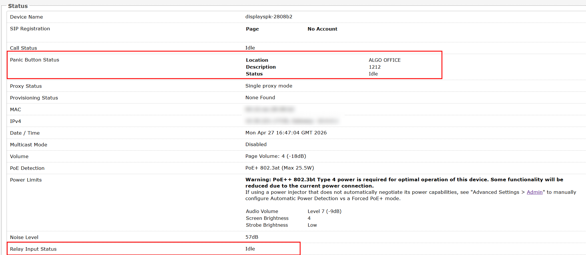
To check your Relay Input status:
Log in to the host Algo IP endpoint’s web interface.
On the Status page, check Relay Input Status or Panic Button Status (if configured).
To view Panic Button status in ADMP:
Log in to ADMP.
Go to Panic Button → Status Overview.
Locate your Panic Button by its IP or MAC address.
.png)