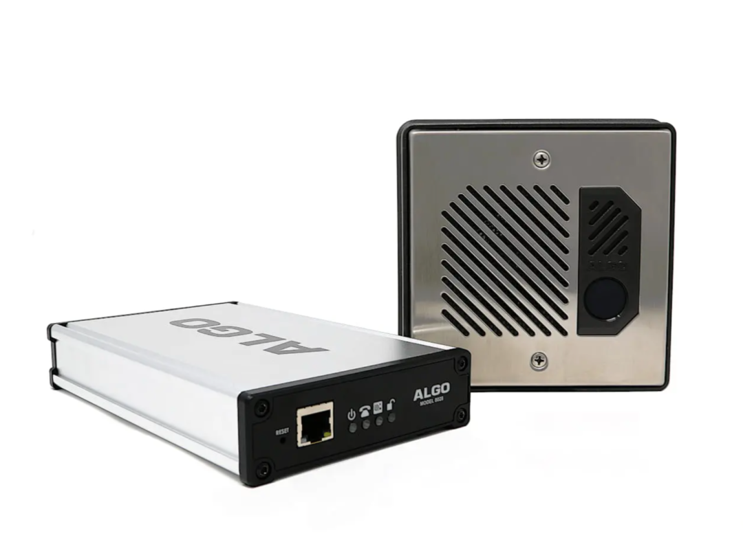
The Algo 8028 IP Doorphone (Controller + Intercom) is a two-device solution that connect to each other via single twisted pair wiring and can be placed up to 1000 ft apart. The 8028 intercom is outdoor-rated with a stainless steel faceplate and does not require an additional network cable drop. The 8028 door control device controls all IP functionality from a secure location like a server room.
The 8028 is the ideal solution for those looking to integrate IP capabilities into their communication system while maintaining the placement and wiring of existing legacy intercoms. As a PoE intercom, you can easily add IP features such as device tampering notifications, wideband audio, and multicast. A vandal-proof version is also available (Algo 8028V Vandal-Proof IP Doorphone (Controller + Intercom)).
This guide is representative of the 8028 G2. The 8028 G1 has fewer features and performs at a lower level. Please consult the 8028 G1 user guide for more details.
Warning
This guide provides important safety information that should be read thoroughly before permanently installing the speaker. It should be noted that this device:
Has a controller intended for indoor locations and a door station intended for outdoor locations
May require earth grounding
Uses a CAT5 or CAT6 connection wiring to an IEEE 802.3at PoE+ or 802.3af compliant network PoE switch that must not leave the building perimeter without adequate lightning protection.
For more details, please see Product Warning below.
Disclaimer
The information contained in this document is believed to be accurate in all respects but is not warranted by Algo. The information is subject to change without notice and should not be construed in any way as a commitment by Algo or any of its affiliates or subsidiaries. Algo and its affiliates and subsidiaries assume no responsibility for any errors or omissions in this document. Revisions of this document or new editions of it may be issued to incorporate such changes. Algo assumes no liability for damages or claims resulting from any use of this manual or such products, software, firmware, and/or hardware.
No part of this document can be reproduced or transmitted in any form or by any means – electronic or mechanical – for any purpose without written permission from Algo.
For additional information or technical assistance in North America, please contact Algo’s support team:
1-604-454-3792
support@algosolutions.com
Product Views
.png)
Front of Controller
Reset Button |
| To return all settings to a factory default, power up the unit and wait until the power light flashes, then press and hold the reset button until the LED starts to double flash. Do not press the reset button until the LED flashes. |
Ethernet Jack (RJ45 Jack) |
| Connect to LAN with access to a SIP-compliant proxy server. |
Power Light |
| Steady: Link and IP address established successfully Flashing: Ethernet link status OK, but IP address not yet obtained |
Telephone Light |
| Off: Not registered or error registering with SIP server Steady: Successfully registered with SIP Server, ready for use Flashing: off-hook or ringing state is currently active |
Door Station Light |
| Steady: the door station is connected Off: Communication errors with the door station, or not connected |
Unlock Light |
| Steady: Door relay is activated. Testing the door control feature: the “unlock” light on the 8028 will turn on (and the mechanical relay may be heard) when the open code is pressed from the telephone keypad during a call with the 8028. This light shows the state of the relay and verifies that it has activated. If the unlock light activates, but the door fails to unlock, please contact your electrician to check the connections and wiring to the door strike. If the unlock light does not turn on, verify that the phone sends a DTMF signal to the doorphone. |
.png)
.png)
.png)
.png)
.png)
.png)
Back of Controller
Power Jack |
| Optional Power Supply | This is an optional power jack if not using PoE/PoE+. Also use for earth GND. |
5 Position Removable Terminal Block |
| Relay (30V 1A) | Normally Open (NO) |
Common (C) | |||
Normally Closed (NC) | |||
24V Auxiliary Power Output (0.25A Power Supply or 0.5A PoE+ needed) | PWR - | ||
PWR + | |||
6 Position Terminal Block |
| Door Station | Connect to CTRL terminal of Door Station |
Door Sensor | Input to controller (e.g. Door Contact, Doorbell Switch); Max 1kOhm | ||
Aux Out | Output from controller; Max 50mA 30V |
.png)
.png)
.png)
Intercom
6 Position Terminal Block |
| Door Station | Connect to CTRL terminal of Door Station |
Door Sensor | Input to controller (e.g. Door Contact, Doorbell Switch); Max 1kOhm | ||
Aux Out | Output from controller; Max 50mA 30V |
.png)
Setup and Installation
What’s Included
8028 IP Doorphone Controller
8028 IP Doorphone Intercom
Outdoor-rated surface mount bezel & gasket kit for door station
Wall mount bracket for control unit
Network Cable 6ft (2m)
Earth grounding strap
2x terminal blocks (one 5-pin connector, one 6-pin connector)
Flat head screwdriver
Not Included
Optional 24V DC Power Supply (Order code 75-00004)
Physical Door Sensor
Door Strike
Door Strike Power Supply
Intercom Installation
Mount the wall bracket securely and snap the 8028 into the bracket by engaging the top and then pushing the bottom firmly into place. To remove the 8028 from the bracket, press firmly on the tab on the bottom catch, then lift the cover.
The 8028 intercom is weather-protected for outdoor installation. However, if network cabling extends beyond the perimeter of the building, adequate lightning protection is required to protect the cabling and network switch from lightning surges. Lightning protection is not required by UL or CSA if the intercom is located on the outside wall of a building and the wiring is inside the perimeter of the building.
The 8028 intercom can be surface or flush mounted.
To surface mount the 8028 intercom:
Ensure the correct orientation of the surface mount gasket.
Thread the wires through the center hole of the larger surface mount gasket, then through the surface mount bracket.
Attach the surface mount bracket to the wall on top of the gasket with drain slot oriented down.
The gasket prevents water ingress behind the bracket and the wall cavity. If the wall surface is irregular, a sealant may be required to prevent water intrusion. Do not block the water drainage slot located on the bottom edge of the bezel.Connect the wire pair to the intercom “CTRL” terminals. Wiring is polarity independent. Note that a yellow caution sticker must first be removed from the intercom terminal socket.
Fasten the intercom to the surface mount bracket and install the faceplate.
.png)
To flush mount the 8028 intercom:
Place the flush mount gasket on the rear of the intercom against the flange.
The purpose of the gasket is to prevent water ingress behind the intercom and the wall cavity. If the wall surface is irregular, a sealant may be required to prevent water intrusion. Do not block the water drainage slot located on the bottom front edge of the intercom.Connect the wire pair to the intercom “CTRL” terminals. Wiring is polarity independent. Note that a yellow caution sticker must first be removed from the intercom terminal socket.
Fasten the intercom to the electrical box and install the faceplate.
.png)
Door or Gate Control Basics
The controller door control relay can be used to unlock a door or gate. No power supply is required for most gate systems that require only a relay contact. Door strikes and magnetic locks, however, do require power to lock or unlock, depending on configuration.
For security, the door control relay is located on the controller to eliminate risk of entry by tampering. When another system is already controlling a door (handicapped access, card reader, etc.), the 8028 may be wired as an additional control system.
Door Release
Door release typically involves energizing or de-energizing a door strike which pivots to allow a locked door to open without retraction of the latch bolt. There are two different types of door strikes:
“Fail Locked” (or “Fail Secure”). These require power to release and remain locked during power failure. The door may still normally be opened from the outside with a key, or from inside without a key. The door control relay is used to apply power to release the door.
“Fail Unlocked” (or “Fail Safe”). These (as well as magnetic locks), require power to lock and become unlocked during power failure. The door control relay is used to maintain power to the door lock (NC and C contacts) which is interrupted to release the door. Magnetic locks may require override systems to allow safety exit in the event of fire.
|
|
.png)
.png)
Power Supply
The 8028 controller has an auxiliary 24 V (0.25A using power supply, 0.5A using PoE+, not available with regular PoE) power supply that is suitable for common types of door strikes. If set to follow door control, this terminal can be wired directly to the door strike (if compatible), without needing to be also wired through the relay.
If a more current or a different voltage is required, a matching power supply for the electric strike or magnetic lock must be used (not included). Maximum switching capability of the 8028 door control contacts is 1 A, 30 V.

Wiring
Earth grounding may be required
Earth grounding is required for installations with door station wiring that leaves the perimeter of a building due to the potential for over-voltage fault conditions.
Note that this requirement does not apply when a door station is installed indoors or on the outside wall of a building if the wiring runs directly into the building. Earth grounding can be achieved by connecting the 8028 (G2) control unit power jack to earth ground using either the supplied ground strap directly to a suitable ground point or by use of the optional Algo 75-00004 24Vdc Power Adapter to socket outlet with a protective earthing connection.
It is highly recommended that when an earth ground is required the control unit be located in a restricted area and that the control unit be secured in place and cable ties used to prevent accidental disconnect of the connection to earth ground. This connection should be verified by a qualified electrician and routinely check as a safety precaution. Under no circumstances can the Control Unit be disconnected from earth ground while connected to outdoor wiring.
Auxiliary Dry Contact Outputs
Both the controller and intercom have a dry contact output for connection to auxiliary devices. Maximum switching capacity is 30 V 50 mA. The intercom output contains an internal opto-coupler, not a true relay, so it will incure a voltage drop of about 2V.
Default operations are as follows:
Controller Output = In-Use (commonly used for camera control)
Intercom Output = Call Button Press (commonly used to activate a secondary doorbell)
Other options for controller output include Ring and Call Button Press.
Other options for intercom output include In-Use and Door Control.
Auxiliary Dry Contact Inputs
Both the controller and intercom can detect a dry contact closure from auxiliary devices. A non-capacitive and non-inductive low voltage and low current is used to detect contact closure.
Default operations include:
Controller input = Door Sensor Normally Closed (used to detect door open)
Intercom input = Call Button Normally Open (used to detect external doorbell switch)
Options for Doorphone Controller input include Door Sensor Normally Closed, Door Sensor Normally Open, Manual Door Release, Door Control Lockout, Call Button Normally Closed, and Call Button Normally Open.
Options for Door Station input include Door Sensor Normally Closed, Door Sensor Normally Open, Call Button Normally Closed, and Call Button Normally Open.
Accessing the Web Interface
Configuration of the 8028 can be completed via the device web interface by entering the IP address of the device in a web browser. The web interface does not require additional purchase. All settings, integrations, and file uploads can be accessed via the web interface. See the configuration chapters below for more details. To access the web interface:
If earth grounding is required, make that connection first before connecting the controller to the network or door station.
Connect the 8028 controller to a network port. If the network switch supports PoE (IEEE 802.3af 15W) or PoE+ (IEEE 802.3at 30W) then the control unit will power up as indicated by the blue power light on the front.
If the network switch does not provide PoE then a PoE injector may be used or the optional Algo 75-00004 24Vdc Power Adapter.The red LED illuminated call button on the front of the intercom will turn on. After about 30 seconds, a beep will signal the completion of the boot process.
After the boot is complete, press the call button on the intercom to hear the IP address. The IP address may also be discovered by momentarily pushing the reset button next to the RJ45 jack or by using an IP scanner tool such as Angry IP Scanner which is free and open-source.
Type the device IP address into a web browser to access the web interface and configure the device. Note that these devices may also or alternatively be configured using centralized provisioning or the Algo Device Management Platform (ADMP).
Login using the default password: algo.
Example Testing Configuration
After logging into the 8028 web interface, navigate to Basic Settings → SIP and enter the IP address or the domain name for the SIP server (provided by your IT team or hosted provider) into SIP Domain (Proxy Server).
Enter the Page and/or Ring credentials Extension, Authentication ID, and Authentication Password (provided by your IT team or hosted provider). If you are not using an extension, leave the fields blank. Note that some SIP servers may say Username instead of Authentication ID.
Verify the extension is properly registered with the SIP server in the Status tab. Ensure the SIP registration says “Successful”.
Test the speaker by dialing the registered SIP extension from an IP phone connected to your network.
Press the call button on the intercom, then answer the phone to communicate over the intercom. Press the digit 6 (default value) on the phone keypad to activate the door control relay for three seconds (if applicable).
Reset
To return all settings to a factory default, reboot or power cycle the 8028. Wait until the power light flashes then press and hold the reset button until the light starts to double flash.
Do not press the reset button until the light begins flashing.
A reset will set all configuration options to factory default including the login password.
Once booting has completed, pressing the intercom call button will trigger the device to play its IP address over the speaker.The 8028 can be used in various ways to enhance paging and alerting systems. The most common use cases and configurations are listed below, with further details about specific configuration settings in later chapters.
Check Device Status
The web interface has a Status page which, by default, is available with and without a login. The Status page can be made exclusive to logged-in users via Advanced Settings → Admin → General → Show Status Section on Status Page when Logged Out.
The Status page contains information such as:
|
|
Register Your Product
You may register your product at https://www.algosolutions.com/product-registration/ to ensure access to the latest upgrades for your device and to receive important service notices.
Security
Algo devices use TLS for provisioning and SIP signaling to mitigate cyberattacks by those trying to intercept, replicate, or alter Algo products. Algo devices also come pre-loaded with certificates from a list of trusted certificate authorities (CA) to ensure secure communication with reputable sources. Pre-installed trusted certificates are not visible to users and are separate from those in the ‘certs’ folder.
For further details, see Securing Algo Endpoints: TLS and Mutual Authentication.
Common Configurations
The 8028 can be used in various ways to enhance paging and alerting systems. The most common use cases and configurations are listed below, with further details about specific configuration settings in later chapters.
Hands-Free Visitor Communication
When a visitor presses the call button on the 8028 intercom, a call will be made to a configured extension, such as a security desk or hunt group. Answering the intercom call enables two-way communication between the answering party and the visitor. During the intercom call, the telephone keypad can be used to enter a door open code (e.g. digit 6, or up to four digits).
Once activated, the 8028 access control relay will permit a momentary unlock of the entrance for the visitor to gain access through the door or gate securely.
Cancel Ring When Door Opened
In a residential or warehouse installation, it is common for the door to be answered in person before the phone is answered. Either intercom or controller inputs can be configured to cancel the ring if the door is opened before a call is answered. This requires a normally closed or normally open contact to detect door open (not included).
Trigger Doorbell from Intercom
When the intercom call button is pressed, either (or both) the intercom or controller dry contact output can be configured to activate a doorbell or auxiliary alerting system in addition to the phone ring.
Trigger Intercom from External Button
Either the controller or intercom can accept a dry contact closure to activate the 8028 as if the call button had been pressed. This could be an external doorbell button, PIR detector, or some other system.
Cancel Door Open Relay Once Door Opened
The door opening control can be set for activation (using the Open Code) up to 30 seconds (set by Duration) to allow sufficient time for entry. For security, the 8028 can be configured to cancel door opening once the door is opened to prevent “tailgating” by unauthorized personnel.
Unlock Door Indefinitely Until Cancelled
The door opening control can be set to unlock indefinitely (using Latch Open Code) until cancelled (using Latch Close Code) to lock the door again. This allows an entrance to be used repeatedly for a period of time without requiring multiple activations of the door control relay.
Anti-Door Tamper
If a door remains open due to being blocked, tampered with, or another issue, the 8028 can be configured to trigger an alert to the connected telephones. This requires a physical door sensor (not included).
In-Use and Ring
Either the controller or intercom can be configured to provide a dry contact output during ring or in-use for channel selection (typically) of third-party video monitoring systems.
Poly Group Paging
The 8028 can be added to a Poly Group Page so that voice paging is heard over Poly telephone speakers and overhead paging simultaneously.
VoIP, UC, or Mass Notification Platform Integration
Algo devices, including the 8028, can integrate with a variety of VoIP platforms including unified communication and mass notification platforms. This can be done via native configurations, SIP registration, or RESTful API.
As a Singlewire Solutions Partner, Algo products have been certified for compatibility and interoperability. To set up your device with Informacast, a license is required. An "-IC" version of the 8028 can be purchased with a license, or the license can be purchased separately. Once the license is acquired, use the web interface and navigate to Advanced Settings → Admin → InformaCast.
Algo devices are certified by and compatible with Microsoft Teams. When registered in the Microsoft Teams SIP Gateway, the 8028 can be configured to deliver Teams-based communication throughout facilities. To set up your device with Microsoft Teams, use the web interface and navigate to Advanced Settings → Admin → Microsoft.
For other UC platforms such as Zoom, RingCentral, and GoTo, or mass notification platforms such as Genetec, and Raptor Technologies, the 8028 can integrate via SIP. To do this, use the web interface and navigate to Basic Settings → SIP to enter your SIP credentials.
See more compatible platforms.
Custom Integrations
The Algo RESTful API enables custom integrations that do not rely on native compatibility or SIP registration.
When the Algo RESTful API is enabled, it can be used to access, manipulate, and trigger the 8028 on your network through HTTP/HTTPS requests. Requesting systems can interact with the 8028 predefined operations.
To configure API settings, use the web interface and navigate to Advanced Settings → Admin → API Support.
See the Algo RESTful API Guide for more details.
Device Management
Algo IP devices can be managed and monitored both on-premise and remotely. The options of device management below help make device maintenance efforts more efficient by reducing the need to manually check devices individually to configure or troubleshoot.
ADMP
The Algo Device Management Platform (ADMP) is a cloud-based device management solution to manage, monitor, and configure Algo IP endpoints from any location. Devices can be easily grouped via a tagging functionality, allowing devices to be coded by district, department, or function to easily oversee many devices. Devices can be supervised for connectivity and email-based notifications can be sent should devices go offline, allowing for a real-time overview of device status.
To connect your device to your ADMP account, use the web interface and navigate to Advanced Settings → Admin → ADMP Cloud Monitoring.
Note that if you choose to use ADMP to manage your devices, the Algo 8300 IP Controller cannot be used at the same time.
Algo 8300 IP Controller
The Algo 8300 IP Controller is designed for centralized on-premise Algo endpoint monitoring and supervision. Any Algo SIP endpoint device can be monitored on the network via the 8300 dashboard.
Note that if you choose to use the Algo 8300 IP Controller to manage your devices, ADMP cannot be used at the same time.
Learn more about the Algo 8300 IP Controller.
SNMP
Simple Network Management Protocol (SNMP) can be used to monitor and manage your device from third-party tools that communicate via SNMP.
To configure your SNMP settings, use the web interface and navigate to Advanced Settings → Admin → Simple Network Management Protocol.
RTCP
Real-Time Transport Control Protocol (RTCP) can be used to monitor data delivery.
To configure your RTCP settings, use the web interface and navigate to Advanced Settings → Advanced Multicast → RTP Control Protocol (RTCP).
SIP Configuration
SIP (Session Initiation Protocol) is a common protocol use by most VoIP, UC, and other IP devices including Algo endpoints. Due to its reliability, SIP makes it easy to scale communication systems and integrate Algo IP devices with other technology.
For the 8028 to use SIP, a SIP license, account, and credentials are required. One license will be required per extension registered. If one device has multiple extensions registered, each registered extension will require a license. On a hosted or cloud platform, the required endpoint extension or seat may be treated the same as any other extension on the system and incur a monthly cost or similar fee.
Basic Settings
Use these SIP settings to enter SIP server information and account credentials. For more details, ask your telephone system administrator or hosted account provider. After entering the information and saving the settings, check the Status tab to confirm the successful registration.
.png)
SIP | |
SIP Domain (Proxy Server) | The SIP Server's IP address (e.g., 192.168.1.111) or domain name (e.g., myserver.com). |
SIP Extension | Enter the SIP extension for the ring parameter of the 8028. This will register the 8028 with the SIP Server. |
Authentication ID | The Authentication ID is associated with the SIP extension. It is also referred to as ‘Username’ for some SIP servers. This may be the same as the Ring or Page extension in some cases. |
Authentication Password | This is the SIP password for the registered SIP account used to authenticate SIP users. |
Display Name (Optional) | Enter the name you want displayed when an SIP call is made. For the display name to be shown, the PBX and phone(s) must be configured to display this message as the Caller ID. |
Extension to Dial | Phone number to be dialed when the call button is pressed. |
Advanced SIP
This section contains additional SIP configurations for more advanced features. These features may not be compatible with all SIP servers. Please consult your SIP Provider or IT team before making changes to these parameters
.png)
General | |
SIP Transportation | Select a transport layer protocol to use for SIP messages from the dropdown. These options include:
|
SIPS Scheme | Only visible when SIP Transportation is set to TLS. Enable to require the SIP connection from endpoint to endpoint to be secure. |
Validate Server Certificate | Enable to validate the SIP server against common certificate authorities. To validate additional certificates, navigate to System → File Manager to upload a Base64 encoded X.509 certificate file in .pem, .cer, or .crt format to the certs folder. |
SIP Outbound Support (RFC 5626) | Enable this option to support best networking practices according to RFC 5626. This option should be enabled if the device is registered with a hosted server or TLS is used for SIP Transportation. |
Outbound Proxy | Enter the IP address for an outbound proxy. |
Register Period (seconds) | Enter the maximum requested period where the device will re-register with the SIP server. The default setting is 3600 seconds (1 hour). Note that if the SIP response 200 (OK) provides an Expires header, this time will take precedence over the Register Period defined time here. Only change if instructed to do so. |
Rate Limit SIP Registration | This option should be used in cases where many SIP extensions are registered (ex. one for each zone). Select a rate limit to stagger registration requests and prevent overloading the server by sending them all at the same time. |
Wait for Successful Unregister | Enable to wait for the device to successfully unregister from the server. Enabling may cause a slight delay during configuration changes and reboots |
SRTP | |
SDP SRTP Offer | Select an option from the dropdown menu:
|
SDP SRTP Offer Crypto Suite | The encryption and authentication algorithms used for voice data. |
NAT | |
Media NAT | IP address for STUN server if present or IP address/credentials for a TURN server. |
ICE – TURN Server | Enter the IP address or domain of the ICE server. |
ICE – TURN User | Enter the username. |
ICE – TURN Password | Enter the password. |
STUN - Server | Enter the IP address or domain of the STUN server. |
Server Redundancy | |
Server Redundancy Feature | Enable to configure up to two secondary backup servers. When enabled, the device will attempt to register with the primary server but switch to a secondary server when necessary. The configuration allows re-registration to the primary server upon availability or to stay with a server until unresponsive. |
Backup Server #1, #2 | Provided by your SIP provider or IT team. |
Polling Intervals (seconds) | Select the time interval for sending monitoring packets to each server from the dropdown menu. Inactive servers are always polled and the active server may optionally be polled. |
Poll Active Server | Enable to explicitly poll the current server to monitor availability. Other regular events may also handle this automatically and can be disabled to reduce network traffic. |
Automatic Fallback | Enable to allow the device to reconnect with a higher priority server once available, even if the backup connection is still working. |
Polling Method | Select a polling method based on what your SIP provider supports. |
Zoom Phone Local Survivability | |
Local Survivability | Enable to re-register with local ZPLS Node if connection to Zoom fails. This allows sites to maintain a subset of Zoom Phone features even if connectivity to the Zoom Phone cloud is lost. |
Survivability Proxy | The IP address or domain name of the local ZPLS node. |
Interoperability | |
Keep-Alive Method | Select a keep-alive method:
|
Keep-Alive Interval (seconds) | Set the interval in seconds that the CRLF message should be sent. 30 seconds is recommended. |
Use Outgoing TLS port in SIP Headers | Enable to use the ephemeral port number from an outgoing SIP TLS connection instead of the listening port number in SIP Contact and Via headers. This is useful for connecting the device to some local SIP servers, like Asterisk or FreeSWITCH. |
Do Not Reuse Authorization Headers | Enable so all SIP authorization information from the last successful request will not be reused in the next request. |
Allow Missing Subscription-State Headers | Enable to allow SIP NOTIFY messages that do not contain a ‘Subscription-State’ header. |
Multicast Configuration
The 8028 can be programmed as a multicast receiver and can be grouped into up to 50 multicast zones. Multicast is a method of transferring data from one transmitter device to multiple receiving devices simultaneously.
Any number and combination of Algo speakers, paging adapters, or visual alerters can be set as receiving devices. Receiving devices do not require a unique SIP extension and therefore do not need to be registered with the SIP server.
In large environments, it is recommended that the device configured as the multicast sender be stored securely to mitigate risk of interference or damage. The 8301 IP Paging Adapter and Scheduler is most often used in these scenarios.
When multiple zones are used, they can be called via DTMF (single extension) or multiple SIP extensions. DTMF codes can be set for a single SIP extension on the transmitter device and dialed to reach the desired DTMF page zone. When multiple SIP extensions are used, each extension is mapped to a unique zone, allowing zones to be called directly.
Multicast IP Addresses
Each 8028 has a unique IP address and shares a common multicast IP and port number (multicast zone) for multicast packets. The transmitter units send to a configurable multicast zone, and the Receiver units listen to assigned multicast zones.
The network switches and router see the packet and deliver it to all the zone members. The multicast IP and port number must be the same on all transmitter and receiver units of the same zone. The user may define multiple zones by picking different multicast IP addresses and/or port numbers.
Multicast IP addresses range: 224.0.0.0/4 (from 224.0.0.0 to 239.255.255.255)
Port numbers range: from 1 to 65535
By default, the 8028 is set to use the multicast IP address 224.0.2.60 and the port numbers 50000-50008
Ensure the multicast IP address and port number do not conflict with other services and devices on the same network.
Using Multicast Page Zones
By default, the 8028 can listen to nine basic multicast zones, however, up to 50 are available. The multicast IP addresses define these zones.
By default these zones have the names below but can be used however you prefer:
Priority
All Call
Zone 1
Zone 2
Zone 3
Zone 4
Zone 5
Zone 6
Music
When set as a multicast receiver, zones have a priority hierarchy where zones higher on the list will be treated with higher priority, with Music being the lowest priority. When set as a multicast transmitter, event priority is based on the event type that initiated the multicast rather than the output multicast channel that will be active.
There are two options for paging to multiple zones:
DTMF Selectable Mode: Has a dynamic page zone selection and requires only the transmitting device to have a registered SIP extension. To page, dial the SIP extension of the transmitter and dial the desired DTMF page zone (e.g., 1, 2, etc.) on the keypad. DTMF digits and their corresponding zone numbers can be found in the Advanced Settings → Advanced Multicast tab of the 8028 web interface.
Multiple page extensions: Multiple SIP extensions can be registered on the transmitter. Each extension is mapped to a unique zone, allowing zones to be called directly.
Multicast: Receiver (Listener)
.png)
Multicast Mode Always ensure that the multicast settings on all Receiver devices match those of the Transmitter. | |
Multicast Mode | If Receiver (Listener) mode is selected, the 8028 will activate when receiving a multicast audio stream. It will mimic the audio stream of the transmitter but use local volume settings. This can be set via Basic Settings → Features → Page Speaker Volume. |
Multicast Type | Select Regular if receiving multicast from other Algo IP endpoint(s) and/or multicast-enabled phone(s) that use RTP audio packets. Select Poly Group Page or Poly Push-to-Talk if receiving multicast paging compatible with Poly “on-premise group paging” protocol. |
Number of Zones | Select Basic Zones Only if configuring nine or fewer multicast zones. Select Basic and Expanded Zones to configure up to 50 zones. The expanded zones have the same behavior as the basic Receiver zones but are hidden by default to simplify the interface. |
Receiver (Listener) Zone Settings | |
Basic Receiver Zones | Select one or more multicast zones for the 8028 to listen to. Multicast zone priority will be based on the zone definition list order defined in Advanced Settings → Advanced Multicast. |
Expanded Receiver Zones | Select additional zones (up to 50) for the device to listen to. This is only possible when Basic and Expanded Zones is selected. |
Poly Group Paging/Push-to-Talk
| |
Poly Zone | Enter the Poly Zone (IP Address and Port) that matches the configuration of the Poly phones and Channels. |
Poly Receiver Channels | If using a Poly telephone as a Multicast Transmitter, a tone may be set for any of the 25 Poly Groups configured on the 8028. Poly Group Tones can be set in Advanced Settings → Advanced Multicast. The Poly telephone used as a page audio source for the 8028 must be configured to use either the G.711 or G.722 audio codec. Note that Poly phone(s) must be configured with the “Compatibility” setting (“ptt.compatibilityMode”) disabled for this codec setting to be applied. |
.png)
Advanced Multicast
These settings are only visible when in Receiver multicast mode. This can be set in Basic Settings → Multicast. The default pre-populated multicast zone IP addresses and ports will work in most cases and should only be altered for rare cases.
.png)
Receiver Settings | |
Audio Sync | Available if the Multicast Mode is set to Receiver (Listener) in Basic Settings → Multicast. When using multicast with other third-party devices that have a delay in their audio path, the audio on the 8028 may be heard slightly earlier than on these other devices. Use this feature to add a small delay on the 8028 to synchronize with these other devices. |
RTP Control Protocol (RTCP) | |
RTCP Port Selection | Select how a port will be chosen to send or receive RTCP packets. Note: If Next Higher Port is selected, ensure that the default multicast zone definitions are modified so that zones are only assigned to even-numbered ports, leaving the next higher odd-numbered ports free for RTCP packets. |
Poly Receiver Tones | |
Poly Receiver Tones | Available if under Basic Settings → Multicast the Multicast Mode is set to Receiver (Listener) and Multicast Type is set to Poly Group Page or Poly Push-to-Talk. A tone may be set for any of the 25 Poly Groups. If using an Algo device as a Multicast Transmitter, it is recommended to set the Receiver tones to None to avoid conflicts, as the Algo devices already multicast a tone by default. |
Door Control Configuration
This section allows security codes to be configured for unlocking the door. This can be done from inside the building using the DTMF keypad on the inside telephone that answers the call.
An electronic door strike is required for unlocking the door (not included). These door strikes typically require their own power system and a contact closure for activation.
Door Controls | |
Test Door Control Relay | Use the Lock and Unlock buttons to test the door control. |
Test 24V Output | Use the Enable and Disable buttons to test the 24V output. |
Door Unlock via Telephone DTMF | |
Momentary Open Code | Enter a 1-4 digit DTMF code that can be used to unlock the door for a brief period of time. Leave this field blank to disable this feature. The default code is “6”. |
Duration | The amount of time to unlock the door for when the Momentary Open Code is entered. From 0.25 to 30 seconds. |
Cancel unlock if Door Opened | Enable the door to re-lock after opening. This option is available only when a physical sensor is installed (not included) on the door and either "Controller Input" or "Door Station Input" is set to "Door Sensor" under Basic Settings → Input/Output tab |
Latch Open Code | Enter a 1-4 digit DTMF code that can be used to unlock the door indefinitely. Leave this field blank to disable this feature. |
Latch Closed Code | Enter a 1-4 digit DTMF code that will lock the door again when it is latched open. Leave this field blank to disable this feature. |
DTMF Detection Type | Different DTMF detection options are given. Use the default of ‘Auto’ unless advised by Algo technical support. |
End Call on DTMF | Enable to terminate the call 2 seconds after the door control DTMF has been received. This feature only applies to the momentary open code. |
Door Unlock on Schedule | |
Unlock via Schedule | If enabled, select a time window for the door to remain unlocked unless locked via another door control feature. |
Tone | |
Use Door Unlock Tone | Allow a tone to be played when the door is unlocked. |
Audio Configuration
Audio configurations for the 8028 include ring settings, page settings, audio processing, emergency alerts, tones, and much more. Use the sections below to understand how each configuration works for audio output and control best suited for the device's environment.
Basic Settings & Features
.png)
Audio | |
Speaker Volume | Select speaker audio level of the 8028 from 1 (lowest) to 10 (highest). Starting from 10 (0 dB), each step reduces the volume by 3 dB, down to -5 (-45 dB). |
Automatic Gain Control (AGC) | Enable or disable AGC to normalize the audio level. Enabling ensures the speaker is always played at a consistent volume. |
Inbound Call | |
Answer Inbound Call | Allow the 8028 to auto-answer an inbound call. By default, this functionality is activated. |
Answer Tone | Select a tone to be played over the speaker when the intercom answers an inbound call. Use only “<Default>” or custom uploaded file. The other pre-installed tone files all contain silence at the end to generate ring "cadence" of 6 seconds. This silence will block the voice path for several seconds at the start of a call. |
Outbound Call | |
Outbound Ring Limit | This feature can be used to set a limit on how long the intercom will ring before timing out. If the call is not answered within this time period, the 8028 will go back to an idle state. |
Ringback Tone | Select an audible ringback tone to be played on the 8028 speaker until the call is answered. |
Play tone to Far End Upon Answer | This feature can be used to play a custom announcement to the answering phone at the start of the call to identify which intercom the call originated from. |
Allow Call Button to End Active Call | If enabled, allows the visitor to end an active call by pressing the call button. |
Cancel Ring if Door Opened | If enabled, cancels an outbound call only if it is still ringing. |
General | |
G.722 Support | Enable or disable the G.722 codec. G.722 enables wideband audio for optimum speech intelligibility. |
Maximum Call Duration | Select the maximum call length. The call will be terminated once the maximum time is reached. If a call inadvertently reaches voicemail or gets accidentally left on hold, this setting ensures that the 8028 returns on-hook. |
Tones
The 8028 includes several pre-loaded audio files that can be selected to play for various events. The web interface allows you to select a file and play it immediately over the speaker for testing, available in Basic Settings → Features. Files may also be added, deleted, or renamed. For more information see File Manager.
.png)
Cache | |
Rebuild Tone Cache Files | Only needed when the tone cache is out of sync. The operation might take a long time depending on the types and sizes of the tone files. |
Test Tones | Listen to uploaded audio files via the device. |
Advanced Audio
.png)
Functions | |
Dynamic Range Compression (DRC) | Enable to compress the dynamic range of page audio to increase loudness. |
Dynamic Range Compression Gain | Select the amount of compression gain from the dropdown menu. More gain increases distortion. |
Jitter Buffer Range | Enter a value between 10-500 to add more buffering if necessary to correct for inconsistent delays on the network. It is recommended to use the lowest value. |
Audio Filters | |
Speaker Filter | Select a frequency from the dropdown to apply a high-pass filter to the speaker output. This setting reduces audio artifacts like humming or buzzing by filtering out unwanted frequencies. |
Speaker Noise Filter | Enable to filter below 145 Hz to reduce mains-induced noise like fans. |
Microphone Filter | Select a frequency from the dropdown to apply a high-pass filter to the microphone input. This setting reduces audio artifacts like humming or buzzing by filtering out unwanted frequencies. |
Microphone Noise Filter | Enable to filter below 145 Hz to reduce mains-induced noise like fans. |
Microphone | |
Microphone Volume | Select a volume for the microphone. |
Silent Microphone Monitoring | |
Outbound Call One-Way Audio (Microphone Only) | When enabled, the relay will prompt only the audio from the 8028 microphone to be heard at the pre-configured extension, while the speaker remains silent. This setting is ideal in settings where silent emergency calls to a pre-configured extension may be needed with a single press of a button. |
Input/Output Configuration
The 8028 has dry contact input and output terminals to connect external accessories, including Algo and third-party accessories.
.png)
Input | |
Controller Input | Select the input connected to the controller unit:
|
Controller Input Mode | Select Normally Open or Normally Closed for the controller input. |
Door Station Input | Select the input connected to the intercom unit:
|
Door Station Input Mode | Select Normally Open or Normally Closed for the intercom input. |
Output | |
Call Button Backlight | Enable or disable the intercom call buttons red backlight. |
Controller Output | Set the controller output event:
|
Door Station Output | Set the intercom output event:
|
Auxiliary 24V Output | |
24V Output | Set Auxiliary 24V output to Disabled, Always On, or Follow Door Control. If set to Follow Door Control, this terminal can be wired directly to the door strike (if compatible) without needing to be also wired through the relay. |
Display Auxiliary Power State on Status Page | If enabled, status of Auxiliary Power State will be shown on the status page. |
Current Limit | Set current limit to low or high. |
Door Sensor | |
Action When Door Opened | Select an action to occur when the door is opened:
|
Max Door Open | Set the amount of time the door can remain open before an alarm will be triggered. |
Call Button | |
Action When Call Button Pressed | Select an action to occur when the intercom call button is pressed:
|
Tone/Pre-recorded Announcement | If Play Tone via Multicast is set, select a tone to be played. |
Cancel Call on Door Unlock | |
Cancel Call if Door Unlocked | If the controller input is set to Manual Door Release, enable or disable a call to be canceled if the door becomes unlocked. |
Door Station Disconnect Alarm | |
Alarm Tone/Pre-recorded Announcement | Select a tone to be played if the intercom is disconnected. |
System Configuration
Network Settings
.png)
Common | |
Internet Protocol | Use the dropdown to select IPv4 Only or IPv4 and IPv6. |
Supersede DNS provided by DHCP | This setting will not appear if the selected Internet Protocol is set to Static. When enabled, this configuration allows DNS settings to be manually configured, replacing ones that may have been provided via DHCP. |
IPv4 | |
IPv4 Method | The device can be set to a static or DHCP IP address. |
IPv4 Address/Netmask | Enter the static IP address and netmask (CIDR format) for the device (e.g., 192.168.1.23/24 where “/24” is equivalent to a netmask of 255.255.255.0). |
IPv4 Gateway | Enter the gateway address. |
IPv6 | |
IPv6 Method | The device can be set to a static or DHCP IP address. |
IPv6 Address/Netmask | Enter the static IP address and netmask (CIDR format) for the device (e.g., 2001:123::abcd:1234/64). |
IPv6 Gateway | Enter the gateway address. |
ICMPv6 Options | |
Destination Unreachable Messages | Enable to restrict traffic by filtering ICMPv6 packets. |
Neighbor Discovery Redirect Messages | Enable to restrict traffic by filtering ICMPv6 packets. |
Anycast Echo Replies | Enable to restrict traffic by filtering ICMPv6 packets. |
Enable Rate Limiting Outbound Messages | Enable to limit the device to respond to other network devices at the specified rate below and prevent it from receiving multiple requests at the same time. |
Rate Limit (packets per second) | Specify the packets per second allowed for Rate Limiting Outbound Messages. |
802.1Q Virtual LAN If the device is using VLAN, you will need to be on the same VLAN to access the web interface, unless routing has been configured between VLANs. | |
VLAN Mode | VLAN tagging is the networking standard that supports Virtual LANs (VLANs) on an Ethernet network. The standard defines a system of VLAN tagging for Ethernet frames and the accompanying procedures to be used by bridges and switches in handling such frames. The standard also provides provisions for a quality-of-service prioritization scheme known as IEEE 802.1p and defines the Generic Attribute Registration Protocol. |
VLAN ID | Specify the VLAN that the Ethernet frame belongs to. The hexadecimal values 0x000 and 0xFFF are reserved. All other values may be used as VLAN identifiers, allowing up to 4094 VLANs. |
VLAN Priority | Set the frame priority level. Otherwise known as Priority Code Point (PCP), VLAN Priority is a 3-bit field that refers to the IEEE 802.1p priority or frame priority level. Values are from 0 (lowest) to 7 (highest). |
802.1X Port-based Network Access Control | |
802.1x Authentication | Enable to add credentials to access LAN or WLAN that have 802.1X network access control (NAC). You can ask your IT Administrator for this information |
Authentication Mode | Select the desired authentication mode. |
Anonymous ID | If configured, the device will send the anonymous ID to the authenticator instead of the 802.1X client username. |
ID | The ID should contain a string identifying the IEEE 802.1X authenticator originating the request. Ask your IT administrator for details. |
Password | Ask your IT administrator for details. |
Validate Server Certificate | Enable to validate the authentication server against common authorities. To validate additional certificates, go to the System → File Manager to upload a Base64 encoded X.509 certificate file in .pem, .cer, or .crt format to the certs folder. |
Differentiated Services | |
SIP (6-bit DSCP value) | Enter the DSCP value for SIP packets. |
RTP (6-bit DSCP value) | Enter the DSCP value for RTP packets. |
RTCP (6-bit DSCP value) | Enter the DSCP value for RTCP packets. |
DNS | |
DNS Caching Mode | There are three mode options: 1. Disabled: No DNS queries will be cached. 2. SIP: Only the results of DNS queries for SIP requests will be cached. 3. All: The results of all DNS queries will be cached |
TLS | |
Allow Weak TLS Ciphers | Enables compatibility with legacy systems that may not support the most current encryptions standards |
Admin
.png)
Admin Password | |
Old Password | Enter the old admin password. The default password when you first get the device is algo. |
Password | Enter a new admin password to log into the device web interface. Make sure the new password is stored safely. If the password is forgotten, you must reset the device entirely with the Reset Button to restore the default password. All other settings will be reset to the original default settings as well. |
Confirmation | Re-enter your new admin password. |
General | |
Device Name (Hostname) | Add a name to identify the device in the Algo Network Device Locator Tool. |
Introduction Section on Status Page | Turn On to show the introduction text on the login screen. |
Show Status Section on Status Page when Logged Out | Turn On to allow others to view the status page without logging in. If turned Off, the settings and configurations on the status page will be hidden entirely unless a user is logged in to ensure only trusted users can view device information. |
Display Switch Port ID on Status Page | Turn On to display the Switch Port ID on the Status Page. This option is only possible if the device is connected to a switch that supports LLDP or CDP. |
Web Interface Session Timeout | Set the maximum duration of inactivity to log a user out of the web interface automatically. |
Play Tone at Startup | The device can play a beep tone at startup. |
Log Settings | |
Log Level | This setting should only be used after consulting with the Algo support team. |
Log Method | Select a Log Method: Local: The log file is saved in RAM on the device. Network: Send the log file to an external SysLog server so settings are not lost if the device is rebooted, or for ease of central access. Both: Use both methods. |
Log Server | Enter the Syslog server address provided by your IT administrator. |
Select Additional Log Events | To be used by support@algosolutions.com if necessary. |
Management | |
Web Interface Protocol | HTTPS is always enabled on the device. HTTP is enabled by default but may be disabled. To do so, select HTTPS Only mode so requests are automatically redirected to HTTPS. |
Force Strong Password | When Enabled, you can enforce a secure password for the device web interface for additional protection. The password requirements for a strong password are:
|
Allow Secure SIP Passwords | When Enabled, SIP passwords are stored in the configuration file in an encrypted format to prevent viewing and recovery. If enabled, navigate to Basic Settings → SIP and fill out the Realm field. To obtain your SIP Realm information, contact your SIP Server administrator or check the SIP log file for a registration attempt. The Realms may be the same or different for all the extensions used. All the configured Authentication Password(s) must be re-entered here as well as any other locations where SIP extensions have been configured to save the encrypted password(s). If the Realm is changed later, all passwords must be re-entered to save the passwords with the new encryption. |
Simple Network Management Protocol | |
SNMP Support | Disabled by default. The existing setting will respond to a simple status query for automated supervision. |
SNMP Community String | Speak to your IT Administrator for more information. |
SNMPv3 Security | Speak to your IT Administrator for more information. |
API Support | |
RESTful API | Disabled by default. Enable a secure API for remote access and device control via HTTP. For more information, see the Algo RESTful API Guide. |
Authentication Method | Speak to your IT Administrator for more information. |
RESTful API Password | Speak to your IT Administrator for more information. |
SCI Support | |
SCI | Disabled by default. Simple Control Interface (SCI) is a separate control interface for certain applications. Its primary purpose is to support phones that may have programmable keys that can only send out HTTP GET requests and allow them to initiate events remotely on an Algo device. |
SCI Password | Enter your SCI password. |
System Integrity | |
System Integrity Checking | Enable this feature to verify that installed system packages have not been tampered with by running a check. Enabling this feature may cause reboots and upgrades to take 30 seconds longer. Verification results can be found on the Status tab. |
Power over Ethernet | |
PoE Power Detection | Use Force PoE+ only when connected to a PoE+ power injector capable of providing 600mA that does not automatically negotiate its power capabilities. Incorrect use of this setting may cause the device to reboot if the power source is not capable of delivering the selected power. |
InformaCast Scenarios API | |
InformaCast Scenario API Support | Enable the device to start an InformaCast Scenario via relay input. This feature can work without an InformaCast license, as only the output device requires a license. |
Microsoft | |
Microsoft Teams Support | Enable to allow the device to register with a Microsoft Teams account. The device reboot will take up to 5 minutes to complete, as the device will communicate several times with the Microsoft server. This feature requires a compatible release from Microsoft. After enabling this setting, please return to the status page to sign into your Teams accounts. This feature requires a compatible release from Microsoft. For more details, please see the Microsoft Teams Configuration Guide. |
ADMP Cloud Monitoring | |
Enable ADMP Cloud Monitoring | The Algo Device Management Platform (ADMP) simplifies the process of managing, monitoring, and maintaining Algo devices from any location. This feature requires a valid Account ID. To learn more about ADMP and how to purchase a license, visit the ADMP webpage. |
Account ID | Enter the account ID listed on the Settings page of your ADMP account. |
Allow Configuration File Sync | Enable ADMP to query and display settings stored on the device. |
Heartbeat Interval | Select how often ADMP should check the status of your device. |
Time
.png)
Time Settings | |
Time Zone | Use the dropdown to select the time zone required for your device. |
NTP Time Server | The interface will attempt to use Timer Server 1 and work down the list if one or more of the time servers become unresponsive. These settings are pre-populated with public NTP servers hosted on the internet. To use these, the device requires internet connection. Alternatively, this can be customized to point the device to any other NTP server hosted or premise-based. |
Supersede NTP provided by DHCP | By default, if an NTP Server address is provided via DHCP Option 42, it will be used instead of the NTP servers listed above. Enable this option to ignore DHCP Option 42. |
NTP Symmetric Key Authentication | To enable, create a new folder in the tab System → File Manager and create a folder named ntp. Upload the symmetric key file and rename the file to ntp.keys. |
Device Date/Time | This field shows the current time and date set on the device. If you are testing the device on a lab network that does not have access to an external NTP server, click Sync with browser to temporarily set the time on the device. This time value will be lost at power down or overwritten if connection to the NTP server is available. Time and date are used for logging purposes. |
Manually Override Time | Manual time and date are intended for testing purposes only. Time will be lost upon power down if the NTP server is reachable. |
Provisioning
Algo devices can be provisioned through a provisioning server or zero-touch provisioning (ZTP).
System administrators can provision multiple Algo devices together, eliminating the need to log into each endpoint web interface. After configuration or firmware files are placed on a provisioning server, Algo devices can be instructed to fetch these files and apply the settings.
Algo also offers a ZTP service that is meant to be used as a redirection service to your provisioning server or to configure your device with an Algo Device Management Platform (ADMP) account. ZTP is enabled by default and occurs before any other provisioning step. It will be disabled automatically after any other provisioning settings are changed on the device for the first time.
Visit the Algo Provisioning Guide for more information.
.png)
Mode | |
Provisioning Mode | Enabling provisioning allows installers to pre-configure the device on a network before installation. This is typically done for large deployments to save time and ensure consistent setups. |
Settings | |
Server Method | Set to Auto by default. Select a Server Method.
For provisioning to work with a DHCP option, DHCP must be enabled under Advanced Settings → Network → IPv4. |
Static Server | Enter the server address or domain. |
Download Method | Select your preferred method for downloading provisioning files. The options are:
The device configuration files can be automatically downloaded from a provisioning server using DHCP Option 66. This option code (when set) supplies a TFTP boot server address to the DHCP client to boot from.
Both protocol and path are supported for Option 66, allowing for http://myserver.com/config-path to be used. |
Config Download Path | Enter the path where the configuration file is located in the provisioning server (e.g., algo/config/8028). |
Firmware Download Path | Enter the path where the configuration file is located in the provisioning server (e.g., algo/config/8028). |
Partial Provisioning | Enable to allow support for “-i” incremental provisioning files. Disable for enhanced security if this is not required. |
Check-sync Behavior | Select Always Reboot to set the device to always reboot despite other settings. |
Sync Start Time | Set a time (HH:MM:SS) for the device to perform a sync according to the Check-sync Behavior setting. Leave this blank if not needed. |
Sync End Time | If set, the device will sync randomly in the window between Sync Start Time and Sync End Time. Setting an End Time earlier than the Start Time indicates an overnight period. Leave blank to sync exactly at the set start time. |
Sync Frequency | Select the sync frequency. Frequency can be set to Daily or Selected Days Only. |
Sync Days | Select the days of the week for syncs to occur. |
Zero Touch Provisioning | ZTP is enabled by default but is disabled when any changes are made to the device configuration. This button can also be used to disable ZTP if no changes have yet been made to the device configuration. |
MD5 Checksum
If using TFTP as a download mode, a .md5 checksum file must be uploaded to the provisioning server In addition to the .conf file. This checksum file is used to verify that the .conf file is transferred correctly without error.
To generate a .md5 file, you can use tools such as http://www.fourmilab.ch/md5. To use this tool, simply download and unzip the .md5 program in a command prompt. The correct .md5 file will be generated in the same directory. To generate lowercase letters, use the “-l” parameter.
Generating a generic configuration file
This configuration file is device-generic in terms of MAC address and will be used by all connected 8028 devices.
If using a generic configuration file, extensions and credentials must be entered manually once the 8028 has automatically downloaded the configuration file.
To see Algo’s SIP endpoint provisioning guide, visit www.algosolutions.com/provision
Generating a specific configuration file
The specific configuration file will only be downloaded by the 8028 with the MAC address specified in the configuration file name.
Since all necessary settings can be included in this file, the 8028 will be ready to work immediately after downloading the configuration file. The MAC address of each 8028 can be found on the back label of the unit.
To see Algo’s SIP endpoint provisioning guide, visit www.algosolutions.com/provision
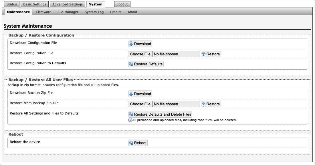
System Maintenance
Backup/Restore Configuration | |
Download Configuration File | Save configuration settings to a text file for backup or to set up a provisioning configuration file. |
Restore Configuration File | Restore settings by uploading a backup file. |
Restore Configuration to Defaults | Reset all device settings to factory default values. |
Backup/Restore All User Files | |
Download Backup Zip File | Download the device configuration settings and the files in File Manager (ex., certificates, licenses, and tones) to a backup ZIP file. |
Restore from Backup Zip File | Restore the device configuration settings and files in File Manager (ex., certificates, licenses, and tones) by uploading a backup zip file. |
Restore All Settings and Files to Defaults | Reset the device configuration settings. All preloaded and uploaded files, including tone files, will be deleted. |
Reboot | |
Reboot the Device | Reboots the device. |
Firmware
.png)
Installed Firmware | |
Product Firmware | Displays the current firmware on the device. |
Online Upgrade | |
Check for Firmware Updates | Click Check to check for the latest firmware. If the firmware is up to date, Latest Firmware will state Firmware up to date. If your firmware is outdated, the new firmware availability will be listed. Internet connection is required. |
Custom Upgrade | |
Method | Select a method for firmware upgrades to occur. This can be done From Local Files or From URL. |
Signed Firmware File | Use to upgrade firmware from a local file. To do this, download the firmware file from https://www.algosolutions.com/firmware-downloads/ then upload the file by clicking on Choose File and selecting the firmware file. |
Upgrade URL | Instead of downloading the firmware file https://www.algosolutions.com/firmware-downloads/, you may add the download link here instead. |
Allow Downgrade | Enable to allow product to be downgraded to an older version. Enabling this option could cause future upgrade issues. |
File Manager
The 8028 has 1 GB of storage space for additional files.
.png)
certs Folder
If you have enabled Validate Server Certificate under Advanced Settings →Advanced SIP or Advanced Settings → Provisioning and want to validate against additional certificates, you can upload them here.
To install a public CA certificate on the Algo device, follow the steps below:
Obtain a public certificate from your Certificate Authority (Base64 encoded X.509 .pem, .cer, or .crt).
Open the certs folder in the web interface by going to System → File Manager.
Upload the certificate files into the certs folder by clicking Upload in the top left corner of the file manager and select the certificate.
Reach out to support@algosolutions.com to get the complete list of pre-loaded trusted certificates.
debug Folder
If you have any challenges with the device and work with the Algo support team to overcome or fix them, the debug folder will be used. The device will generate files containing information about the device and put them in the debug folder. You do not need to use this folder unless directed to by the Algo support team.
license Folder
If you would like to use Informacast on a device that hasn't been bundled with an Informacast license, you will need to purchase a license and put it into the license folder in the file manager.
tones Folder
Custom audio files may be uploaded to play notifications. Audio files should be stored in the tones directory.
Existing files may be modified by downloading the original file, making the desired changes, then uploading the updated file with a different name. To download, right-click the tone and click Download.
Audio files must be in the following format:
• WAV or MP3 format
• Smaller than 200 MB
File names must be limited to 32 characters, with no spaces.
For further instructions, reference the Custom Tone Conversion and Upload Guide.
System Log
System log files are automatically created and can assist with troubleshooting if the device does not behave as expected..png)
Log Out
Log out of the web interface.
Specifications
View 8028 device technical specifications.
FCC Compliance Statement
This equipment has been tested and found to comply with the limits for a Class A digital device, pursuant to Part 15 of the FCC Rules. These limits are designed to provide reasonable protection against harmful interference when the equipment is operated in a commercial environment. This equipment generates, uses, and can radiate radio frequency energy, and if it is not installed and used in accordance with the instruction manual, it may cause harmful interference to radio communications. Operations of this equipment in a residential area is likely to cause harmful interference, in which case the user will be required to correct the interference at their own expense.
Product Warnings
Important Notice
This product is powered by a certified limited power source (LPS), Power over Ethernet (PoE); through CAT5 or CAT6 connection wiring to an IEEE 802.3at PoE+ or 802.3af compliant network PoE switch. The product is intended for installation indoors. All wiring connections to the product must be in the same building. If the product is installed beyond the building perimeter or used in an inter-building application, the wiring connections must be protected against over voltage/transient. Algo recommends that this product be installed by a qualified electrician.
If you are unable to understand the English language safety information then please contact Algo by email for assistance before attempting an installation support@algosolutions.com.
Emergency Communication
If used in an emergency communication application, the 8028 IP Doorphone (Controller + Intercom) should be routinely tested. SNMP or ADMP supervision is recommended for assurance of proper operation. Contact Algo for other methods of operational assurance.
Earth Grounding May Be Required
Earth grounding is required for installations with door station wiring that leaves the perimeter of a building due to the potential for over-voltage fault conditions.
Note that this requirement does not apply when a door station is installed indoors or on the outside wall of a building if the wiring runs directly into the building. Earth grounding can be achieved by connecting the 8028 control unit power jack to earth ground using either the supplied ground strap directly to a suitable ground point or by use of the optional Algo 75-00004 24Vdc Power Adapter to socket outlet with a protective earthing connection.
It is highly recommended that when an earth ground is required the control unit be located in a restricted area and that the control unit be secured in place and cable ties used to prevent accidental disconnect of the connection to earth ground. This connection should be verified by a qualified electrician and routinely check as a safety precaution. Under no circumstances can the controller be disconnected from earth ground while connected to outdoor wiring.
Wet or Outdoor Environments
The 8028 IP Doorphone (Intercom & Controller) controller is intended for indoor locations and the intercom is intended for outdoor locations and may be subjected to spray or weather, provided the rear wiring cavity is properly sealed to prevent water ingress.
Gaskets included with the intercom may be effective against water ingress on some, but not all surfaces in which case additional protective measures must be taken such as a perimeter sealant.
CAT5 or CAT6 connection wiring to an IEEE 802.3af or IEEE 802.3at compliant network PoE/PoE+ switch must not leave the building perimeter without adequate lightning protection.
When the intercom is connected to wiring that exits the building, there is potential risk of lightning induced electrical surges or high voltages from fault conditions. To reduce risk, outdoor wiring should be protected by Earth grounded conduit whenever possible. Relay input and output connections must not leave the building perimeter without adequate lightning protection.