Disclaimer
The information contained in this document is believed to be accurate in all respects but is not warranted by Algo. The information is subject to change without notice and should not be construed in any way as a commitment by Algo or any of its affiliates or subsidiaries. Algo and its affiliates and subsidiaries assume no responsibility for any errors or omissions in this document. Revisions of this document or new editions of it may be issued to incorporate such changes. Algo assumes no liability for damages or claims resulting from any use of this manual or such products, software, firmware, and/or hardware.
No part of this document can be reproduced or transmitted in any form or by any means – electronic or mechanical – for any purpose without written permission from Algo.
For additional information or technical assistance in North America, please contact Algo’s support team:
1-604-454-3792
support@algosolutions.com
Important Warning and Safety Information
.png) Important Notice
Important Notice
This product is powered by a certified limited power source (LPS), Power over Ethernet (PoE); through CAT5 or CAT6 connection wiring to an IEEE 802.3af compliant network PoE switch. The product is intended for installation indoors. All wiring connections to the product must be in the same building. If the product is installed beyond the building perimeter or used in an inter-building application, the wiring connections must be protected against overvoltage/transient. Algo recommends that this product is installed by a qualified electrician.
If you are unable to understand the English language safety information, then please contact Algo by email for assistance before attempting an installation support@algosolutions.com.
Consignes de Sécurité Importantes
Ce produit est alimenté par une source d’alimentation limitée certifiée (alimentation par Ethernet); des câbles de catégorie 5 et 6 joignent un commutateur réseau à alimentation par Ethernet homologué IEEE 802.3at / 802.3bt Le produit est conçu pour être installé à l’intérieur. Tout le câblage rattaché au produit doit se trouver dans le même édifice. Si le produit est installé au-delà du périmètre de l’édifice ou utilisé pour plusieurs édifices, le câblage doit être protégé des surtensions transitoires. Algo recommande qu’un électricien qualifié se charge de l’installation de ce produit.
Si vous ne pouvez comprendre les consignes de sécurité en anglais, veuillez communiquer avec Algo par courriel avant d’entreprendre l’installation au support@algosolutions.com.
Información de Seguridad Importante
Este producto funciona con una fuente de alimentación limitada (Limited Power Source, LPS) certificada, Alimentación a través de Ethernet (Power over Ethernet, PoE); mediante un cable de conexión CAT5 o CAT6 a un conmutador de red con PoE en cumplimiento con IEEE 802.3af. El producto se debe instalar en lugares cerrados. Todas las conexiones cableadas al producto deben estar en el mismo edificio. Si el producto se instala fuera del perímetro del edificio o se utiliza en una aplicación en varios edificios, las conexiones cableadas se deben proteger contra sobretensión o corriente transitoria. Algo recomienda que la instalación de este producto la realice un electricista calificado.
Si usted no puede comprender la información de seguridad en inglés, comuníquese con Algo por correo electrónico para obtener asistencia antes de intentar instalarlo: support@algosolutions.com.
Wichtige Sicherheitsinformationen
Dieses Produkt wird durch eine zertifizierte Stromquelle mit begrenzter Leistung (LPS – Limited Power Source) betrieben. Die Stromversorgung erfolgt über Ethernet (PoE – Power over Ethernet). Dies geschieht durch eine Cat-5-Verbindung oder eine Cat-6- Verbindung zu einer IEEE 802.3af-konformen Ethernet-Netzwerkweiche. Das Produkt wurde konzipiert für die Installation innerhalb eines Gebäudes. Alle Kabelverbindungen zum Produkt müssen im selben Gebäude bestehen. Wenn das Produkt jenseits des Gebäudes oder für mehrere Gebäude genutzt wird, müssen die Kabelverbindungen vor Überspannung und Spannungssprüngen geschützt werden. Algo empfiehlt das Produkt von einem qualifizierten Elektriker installieren zu lassenv.
Sollten Sie die englischen Sicherheitsinformationen nicht verstehen, kontaktieren Sie bitte Algo per Email bevor Sie mit der Installation beginnen, um Unterstützung zu erhalten. Algo kann unter der folgenden E-Mail-Adresse erreicht werden: support@algosolutions.com.
安全须知
本产品由认证的受限电源(LPS),以太网供电(PoE),通过CAT5或CAT6 线路联接至 IEEE 802.3af 兼容的 PoE 网络交换机供电。本产品适用于室内或建筑物周边安装。所有联 接本产品的线路必须源自同一建筑物。本产品如需用于超出建筑物周边范围或跨建筑物的安 装,线路联接部分必须有过压和瞬态保护。Algo 建议本产品由专业电工安装。
如果您对理解英文版安全须知有问题,安装前请通过电子邮件和 Algo联系support@algosolutions.com.
EMERGENCY COMMUNICATION
If used in an emergency communication application, the 8305 IP Paging Adapter & Scheduler should be routinely tested. SNMP supervision is recommended for assurance of proper operation. Contact Algo for other methods of operational assurance.
DRY INDOOR LOCATION ONLY
The 8305 IP Paging Adapter & Scheduler is intended for dry indoor locations only. For outdoor locations, Algo offers weatherproof speakers and strobe lights.
CAT5 or CAT6 connection wiring to an IEEE 802.3af (PoE) compliant network PoE switch must not leave the building perimeter without adequate lightning protection.
No wiring connected to the 8305 IP Paging Adapter & Scheduler may leave the building perimeter without adequate lightning protection.
Product Overview
Introduction
Algo’s 8305 Multi-Interface IP Paging Adapter is a SIP-compliant, PoE device that enables you to integrate legacy communication systems and IP devices. Designed specifically to emulate an analog phone, the 8305 enables you to create a hybrid VoIP environment by continuing to use existing analog hardware connected to a telephone port, 8 Ω output, or line output.
The 8305 can act as a transmitter or receiver, giving you full control of your multicasting needs. Using wideband audio (G.722 voice codec), the 8305 allows you to deliver clear, crisp audio and high speech intelligibility for voice pages, tones, and alerts. The device also has calendaring functionality to set bell, announcement, or other notification schedules using audio files stored on the 8305. These can be single events or recurring events that play daily, weekly, monthly, or annually.
Compared to the Algo 8301 IP Paging Adapter & Scheduler which has the most versatility of Algo paging adapters and the Algo 8373 IP Zone Paging Adapter which was designed to eliminate the need for a legacy zone controller, the 8305 Multi-Interface IP Paging Adapter is best suited for those wanting to scale their use of a legacy communication system for paging.
Product Views

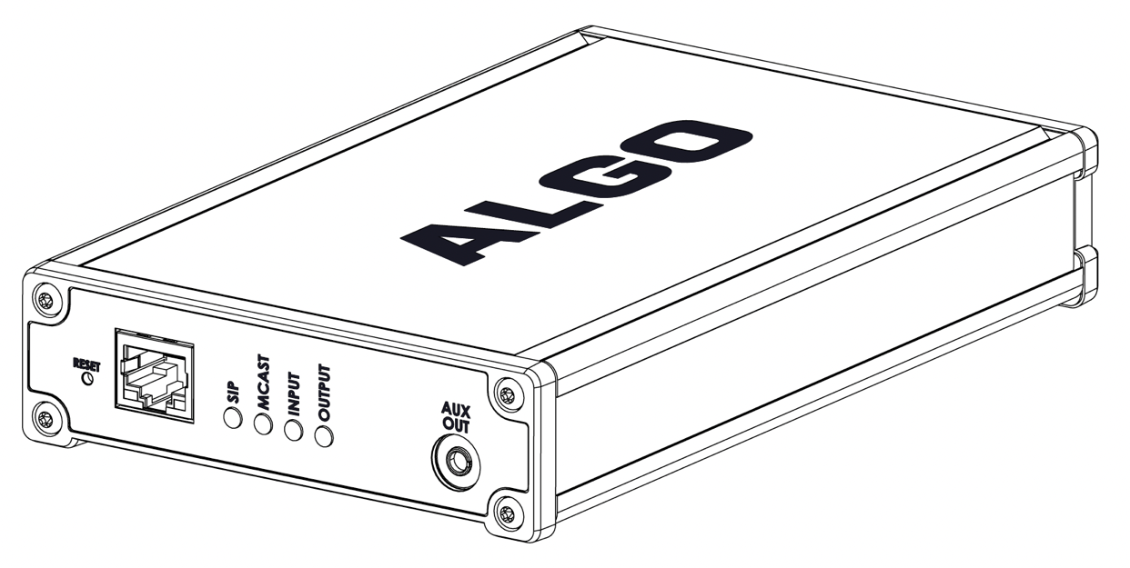
Figure 1: 8305 Multi-Interface IP Paging Adapter front faceplate.
8305 - Right Side | |
RESET Button | A recessed reset button. This button is used to reset the device or play the device’s IP address during setup. |
RJ45 Ethernet Jack | For network connection. A cable run from the switch can be terminated to a modular jack with a connection by patch cord or terminated with an RJ45 plug. PoE (Power over Ethernet) must be 48 V 350 mA IEEE 802.3af compliant, whether provided by the network switch or injector. |
RJ45 Ethernet Jack Light | There are two lights on the Ethernet jack:
|
SIP Light (Blue) | A steady light will appear when a SIP extension is registered. The light will blink when the device is engaged in a SIP call. |
MCAST Light (Blue) | A steady light will appear when the 8305 receives multicast audio as a Receiver. The light will blink when the 8305 sends multicast audio as a Transmitter. |
INPUT Light (Blue) | Not currently used on this device. |
OUTPUT Indicator (Blue) | Turns on when the analog output is enabled. |
AUX OUT 3.5 mm Jack | Analog line level output for compatible PC speakers or headset. Non-isolated. |
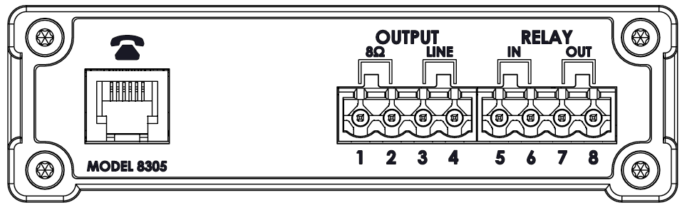
Figure 2: 8305 Multi-Interface IP Paging Adapter back faceplate.
8305 - Left Side | |
Telephone Port | Emulates an analog telephone that can go on and off hook. Has built in ring detection with auto-answer. The telephone port is intended only for the connection to the FXS port on a legacy communication system and must not be connected to the PSTN. |
Terminal Block 8 W Output (1/2) | Balanced and isolated wire pair output to connect one or many external self-amplified speakers connected in parallel with a total minimum resistance of 8 W. Intended use is for up to 100 nominal 2 kW or 1 kW self-amplified speakers. 8 W maximum output: +3dBm @ 8 W 2 kW maximum output: +1.5dB higher |
Terminal Block Line Output (3/4) | Balanced and isolated wire pair. Output level defined using web interface. |
Terminal Block Relay In (5/6) | Used to connect an external button or to detect a contact closure. Connection options include a normally closed switch, normally open switch, 1202 Call Button, 1203 Call Switch, 1204 Volume Control Switch, 1205 Audio Interface, or EOL resistor termination. |
Terminal Block Relay Out (7/8) | By default, these terminals provide a contact closure when the 8305 IP Paging Adapter is active. Note this is a normally open relay only. |
Setup and Installation
Note
Read thoroughly to understand essential safety information before installing the product permanently.
What is Included
The following items are included with this device:
8305 Multi-Interface IP Paging Adapter
Wall mount bracket and screws
Network cable
Two (2) pluggable terminal blocks
Flat head screwdriver
Quick Start Guide
Hardware Setup & Installation
Mounting Instructions
Use the supplied bracket to mount the 8305 horizontally. The following instructions can be used to install the 8305 on a 1/2” drywall:
|
Figure 3: 8305 wall mount. |

Wiring Connections
Connect the 8305 Multi-Interface IP Paging Adapter to an IEEE 802.3af compliant PoE network switch or PoE injector. Blue lights on the front will turn on.
Wait for the blue lights to turn off (about one minute). Boot-up is complete when they turn off.
Press the recessed reset switch (RST) to play the IP address over the analog outputs. A headset can be connected to the green AUX output port. You can also find the IP address by downloading the Algo Network Device Locator or a third-party network scanner to find Algo devices on your network. Algo device MAC addresses start with 00:22:ee. You will need this IP address to configure the 8305 using the web interface.
Connect your desired devices to the telephone port, line output, or 8 W output.
Telephone Port – Connect to the telephone port on a legacy communication system. This port on the 8305 emulates an analog phone. The telephone port on the legacy device may be labeled as an FXS port.
Line Output – Connect directly to the telephone input on the legacy communication system with an input impedance between 600 Ohm and 10 kOhm. The output level can be adjusted to match the device’s input volume and other audio specifications in the web interface under Basic Settings → Features. If required, the optional dry contact closure can be used to activate the legacy communication system.
8 W Output – Connect one or many self-amplified speakers. If many speakers are connected in parallel, the resulting effective impedance must not be less than 8 W. Intended use is for nominal 2 kW or 1 kW self-amplified speakers.
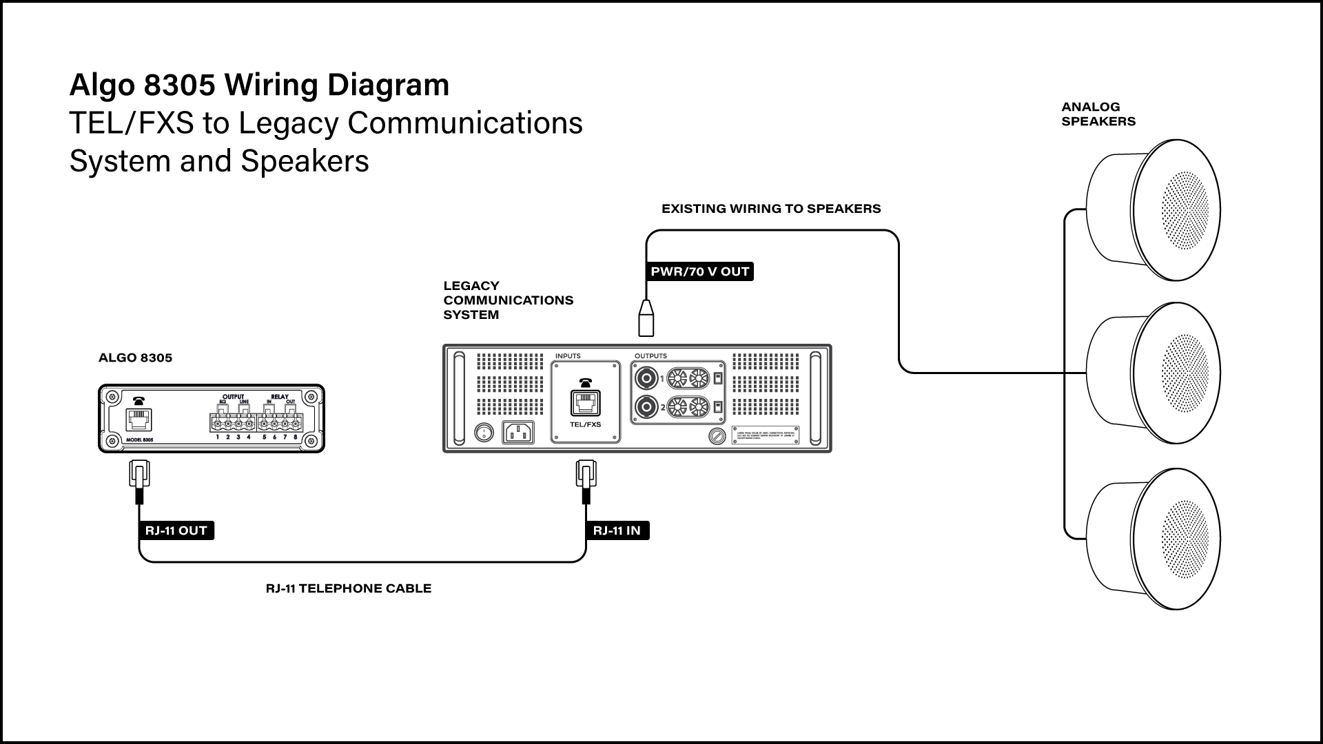
Figure 4: Wiring diagram example for the 8305.
Accessing the Web Interface
After you enter the IP address for your device into your browser, the web interface will appear.
You must log in to view device settings. The default password is algo. This password can be changed under Advanced Settings → Admin after logging in. Changing the default password is highly recommended if the device is directly connected to a public network.
Note
The Save button must be clicked to apply any changes made in the web interface.
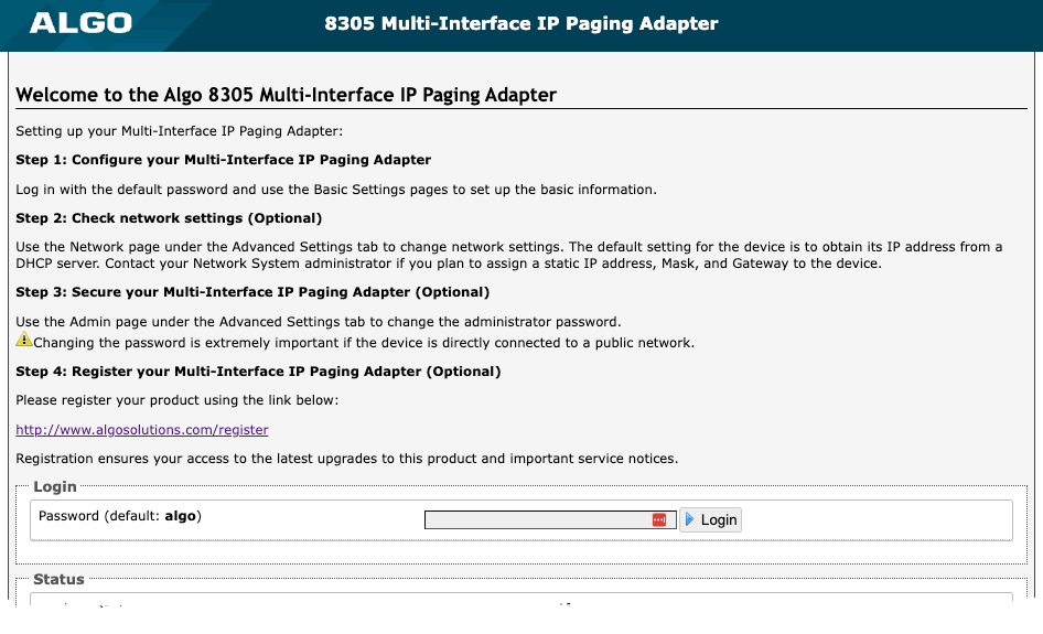
Figure 5: Welcome page for the 8305 web interface.
Web Interface Setup
Enter the IP address into a web browser to access the 8305 Multi-Interface IP Paging Adapter web interface.
Log in using the default password: algo.
Navigate to Basic Settings → SIP and enter the IP address or the domain name for the SIP server (provided by your IT team or hosted provider) into SIP Domain (Proxy Server).
Enter the Page and/or Ring credentials Extension, Authentication ID, and Authentication Password (provided by your IT team or hosted provider). If you are not using an extension, leave the fields blank.
Note
Some SIP servers may say Username instead of Authentication ID.
Verify the extension is properly registered with the SIP server in the Status tab. Ensure the SIP registration says “Successful”.
Test the adapter by dialing the registered SIP extension from an IP phone connected to your network.
Check Device Status
By default, the Status page is available with and without a login. You may make the Status page only available to logged-in users via Advanced Settings → Admin → General → Show Status Section on Status Page when Logged Out.
The Status page contains information such as:
|
|
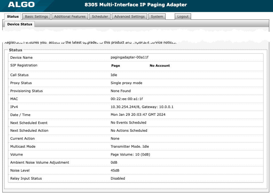
Figure 6: Device status tab.
Register Your Product
You may register your product at https://www.algosolutions.com/product-registration/ to ensure access to the latest upgrades for the 8305 and receive important service notices.
Reset
The recessed reset button (RST) next to the Ethernet Jack can only reset the 8305 Multi-Interface IP Paging Adapter during power-up. A reset will set all configuration options to factory default, including the login password.
To return all the settings in the 8305 to the factory default:
Reboot or power cycle the 8305.
When the SIP LED flashes, press and hold the reset button until the SIP LED begins a double flash pattern.
Release the reset button and allow the unit to complete its boot process.
Once booting is complete, press the reset button to play the IP address via the analog output ports.
Security
Algo devices use TLS for provisioning and SIP signaling to mitigate cyberattacks by those trying to intercept, replicate, or alter Algo products. Algo devices also come pre-loaded with certificates from a list of trusted certificate authorities (CA) to ensure secure communication with reputable sources. Pre-installed trusted certificates are not visible to users and are separate from those in the ‘certs’ folder.
For further details, see Securing Algo Endpoints: TLS and Manual Authentication.
SIP Configuration
SIP signaling is the underlying protocol for transmitting SIP messages between different entities in a network. SIP signaling establishes the call but does not contain the audio.
The 8305 can function as an IP telephone in a system with a simple configuration when a connected SIP extension is called. Also called a page extension, this enables the 8305 Multi-Interface IP Paging Adapter to recognize the configured extension and auto-answer when called.
A SIP endpoint license associated with a UC platform may be required to register the 8305. One license will be required per extension registered. If one device has multiple extensions registered, each registered extension will require a license. On a hosted or cloud platform, the required endpoint extension or seat may be treated the same as any other extension on the system and incur a monthly cost or similar fee.
Basic Settings
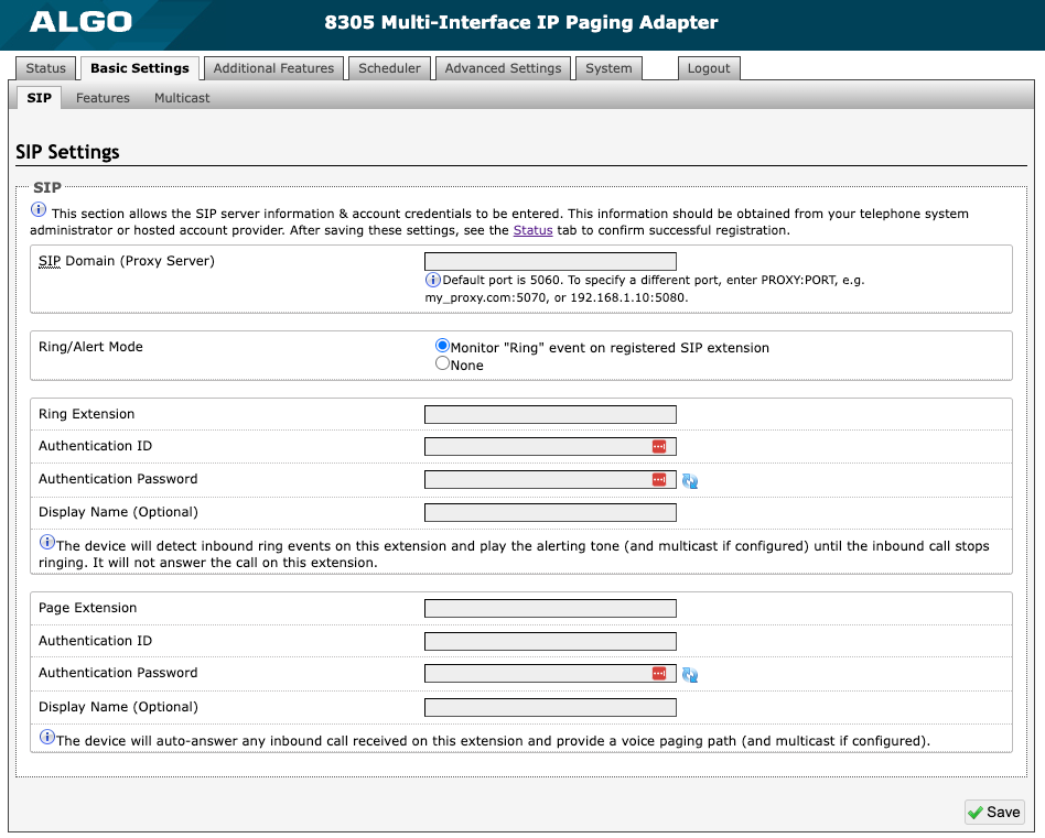
Figure 7: Configure basic SIP settings.
Use these SIP settings to enter SIP server information and account credentials. You can ask your telephone system administrator or hosted account provider for more details. After entering the information and saving the settings, check the Status tab to confirm the successful registration.
SIP | |
SIP Domain (Proxy Server) | The SIP Server's IP address (e.g., 192.168.1.111) or domain name (e.g., myserver.com). |
Ring/Alert Mode | Ring extensions do not answer incoming calls but play a customizable, pre-recorded announcement, such as a loud ringer (night bell). Announcements are customizable and can be pre-recorded. Use this setting to add a second SIP extension for a Ring event. If Monitor "Ring" event on registered SIP extension is selected, you will see additional settings for Ring extension parameters. None is set by default. If set, the device will detect inbound ring events on this extension and play the alerting tone (and multicast if configured) until the inbound call stops ringing. The 8305 will not answer the call on this extension. Often, the 8305 will be a member of a hunt group or ring group to ring in conjunction with a telephone. You may change the alert tone via Basic Settings → Features. |
Ring Extension | Enter the SIP extension for the ring parameter of the 8305. |
Page Extension | Page extensions auto-answer and open a voice path, enabling live announcements. Enter the SIP page extension for the 8305 so the device will auto-answer any inbound call received on this extension and provide a voice paging path (and multicast if configured). |
Authentication ID | The Authentication ID is a name that represents the page extension. It is also referred to as ‘Username’ for some SIP servers. This may be the same as the Ring or Page extension in some cases. |
Authentication Password | This is the SIP password for the registered SIP account. Up to eight (8) characters can be used. The password can be used to authenticate SIP users. |
Display Name (Optional) | Enter the name you want displayed when an SIP call is made. For the display name to be shown, the PBX and phone(s) must be configured to display this message as the Caller ID. |
More Page Extensions
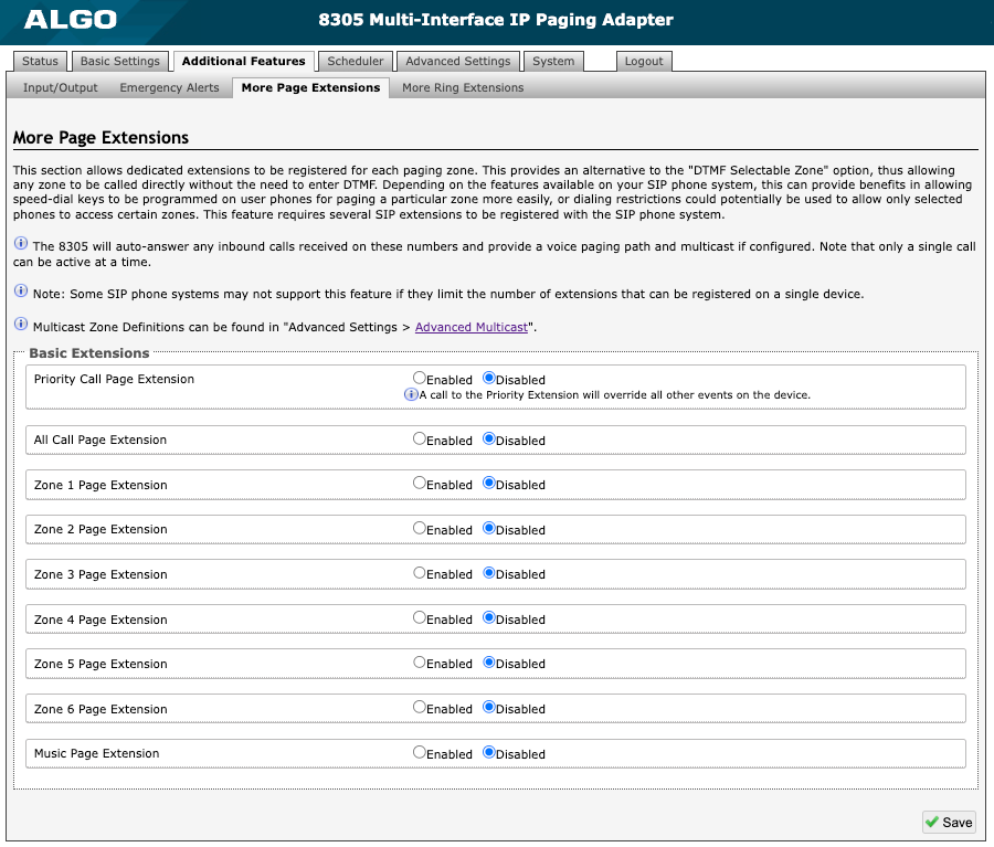
Figure 11: More page extensions.
Additional SIP paging extensions can be registered for each multicast zone. This enables you to dial a zone directly without entering DTMF Codes; however, this may require additional SIP licenses depending on the SIP provider. Some SIP telephone systems may not support this capability altogether if there is a limit on the number of extensions registered on a single device.
To configure additional page extensions (up to 50):
Select ‘Enable’ beside the extension of interest.
Enter the Extension, Authentication ID, and Authentication Password. You may enter a Display Name if you’d like.
The 8305 will auto-answer any inbound calls received on these numbers and provide a voice paging path and multicast if configured. Only a single call can be active at a time.
More Ring Extensions
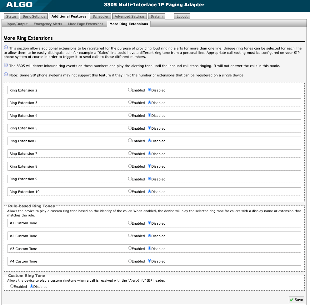
Figure 17: More ring extensions.
Up to 10 SIP Ring extensions can be registered. To configure additional ring extensions, select Enabled beside an extension and enter the Extension, Authentication ID, and Authentication Password. If desired, a unique ringtone and multicast zone can be assigned to each extension.
Set a rule-based ringtone so the device plays a custom ringtone based on the caller's identity. When enabled, the device will play the selected ringtone for callers with a display name or extension that matches the rule.
Enable a custom ring to allow the device to play a custom ringtone when receiving a call with the "Alert-Info" SIP header.
Emergency Alerts
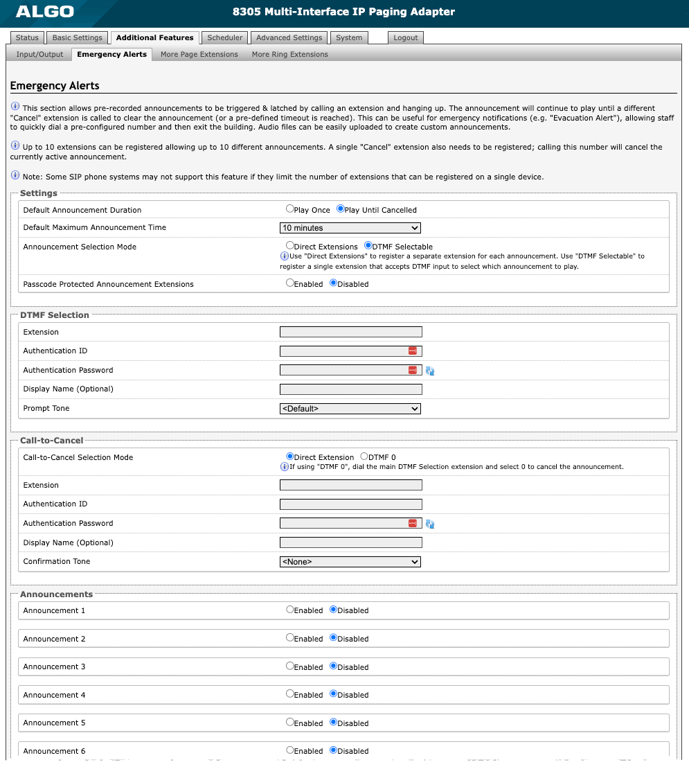
Figure 15: Emergency Alerts.
The 8305 is often used for emergency (e.g., lockdown, evacuation, reverse evacuation), safety (e.g., medical, workplace accident), and security events (e.g., OSHA or similar workplace regulations) alerting.
Emergency alerts notify others of an emergency quickly and efficiently. Users can trigger and latch an emergency alert or announcement by dialing a pre-configured extension (of which you may have many) or dial a single SIP extension and use DTMF to select an announcement. The announcement will continue to play on a loop until a different “Call-to-Cancel” extension is called to clear the announcement or a pre-defined timeout is reached.
Up to 10 extensions can be registered, allowing up to 10 different announcements. A single “Call-to-Cancel” extension also needs to be registered. Calling this number will cancel an active announcement.
Note
Some SIP telephone systems may not support this feature if they limit the number of extensions that can be registered on a single device.
Settings
| |
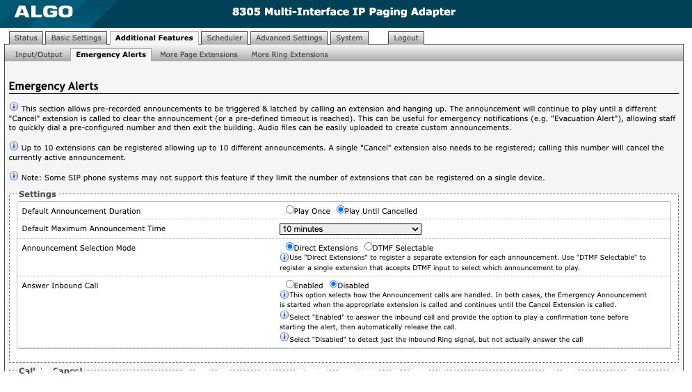
Default Announcement Duration | An announcement can be played once or continuously until canceled. Select Play Once to play a single cycle of the chosen tone file. If Play Until Cancelled is selected, the announcement will continue to play until the "Call-to-Cancel" extension is called to clear the announcement or a defined timeout is reached. |
Default Maximum Announcement Time | Select the maximum time an announcement can be played. |
Announcement Selection Mode | Select Direct Extensions to register a separate extension for each announcement. Select DTMF Selectable to register a single extension that accepts DTMF input to select which announcement to play. |
Answer Inbound Call | This setting indicates how Announcement calls are handled. In both cases, the Emergency Announcement is started when the appropriate extension is called and continues until the “Call-to-Cancel” extension is called. Select Enabled to answer the inbound call and provide the option to play a Confirmation Tone before starting the alert, then automatically release the call or request a passcode before playing the announcement. Select Disabled to detect the inbound Ring signal but not answer the call. Select Disabled to only detect the inbound Ring signal, but not answer the call. In both instances, the announcement will play until the time limit is reached or the “Call-to-Cancel” extension is called. Enabling Answer Inbound Call can be useful when the caller cannot hear the announcement from their location. However, if the call might go to a group or multiple extension(s) (including this device), the auto-answer may intercept that call and prevent it from ringing on other devices. |
Passcode Protected Announcement Extensions | Select Enabled to require the caller to enter a passcode after dialing an announcement or “Call-to-Cancel” extension. Setting a passcode helps prevent unintentional announcements. |
Announcement Passcode | Enter a passcode that a caller must enter to play or cancel an announcement. When prompted, the caller must enter the passcode followed by the # sign before the announcement will be played or canceled. The passcode prompt will be played before any other action. If the passcode is not correctly entered within 15 seconds, the call will end. |
Passcode Prompt Tone | Select a tone to play when the passcode is ready to be entered. |
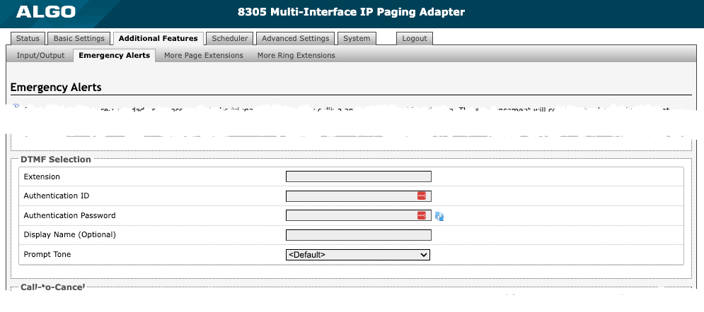
DTMF Selection
| |
Extension | Enter the SIP extension for the DTMF Selection parameter of the 8305. |
Authentication ID | Enter the Authentication ID. It may also be called Username for some SIP servers or may be the same as the extension. |
Authentication Password | Enter the SIP password provided by the system administrator for the SIP account. |
Display Name (Optional) | Enter a ‘Display Name’ that will be sent when the SIP call is made. The PBX and phone(s) must be configured to display this message as the Caller ID. |
Prompt Tone | Select a tone to play when the passcode is ready to be entered. |
Call-to-Cancel
| |
Call-to-Cancel Selection Mode | If using “DTMF 0”, the user should dial the main DTMF Selection extension and select ‘0’ to cancel the announcement. |
Extension | Enter the SIP extension for the Call-to-Cancel Selection parameter of the 8305. |
Authentication ID | Enter the Authentication ID provided by the System Administrator. It may also be called Username for some SIP servers or may be the same as the extension. |
Display Name (Optional) | Enter a ‘Display Name’ that will be sent when the SIP call is made. The PBX and phone(s) must be configured to display this message as the Caller ID. |
Prompt Tone | Select a tone to play when the passcode is ready to be entered. |

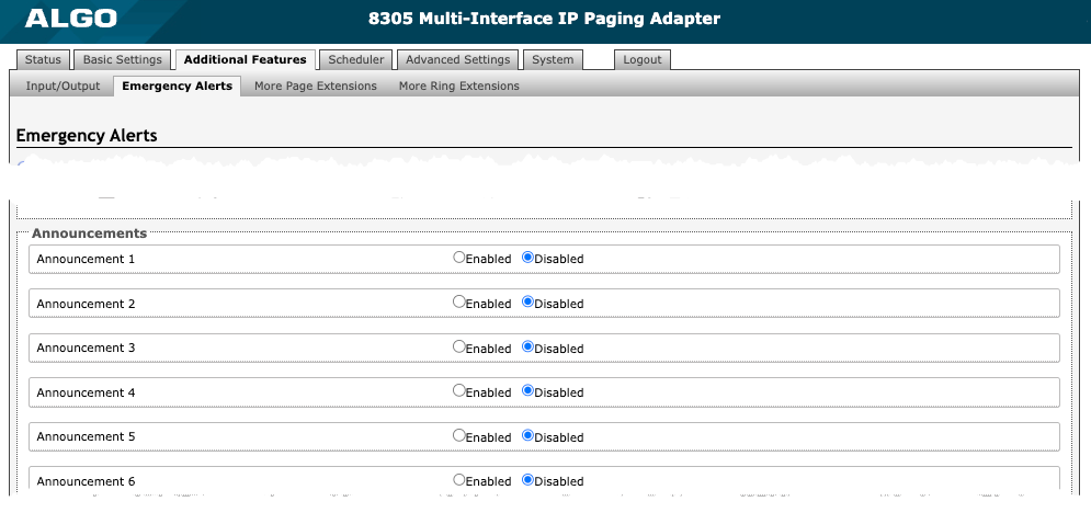
Announcements
| |
Announcement # | To configure an Emergency Alert extension, select Enabled for an announcement number. Up to 10 extensions can be registered allowing up to 10 different announcements. Audio files can be easily uploaded to create custom announcements. Only one ‘Call-to-Cancel’ extension is needed. Some SIP telephone systems may not support multiple announcements if they limit the number of extensions that can be registered on a single device. |
Announcement Duration | Choose the duration of an announcement. The Default option follows the behavior configured in Default Announcement Duration. |
Maximum Announcement Time | Select the maximum announcement time. |
Tone/Pre-recorded Announcement | Select a file to use as a ringtone or announcement. |
Confirmation Tone | Select a file to use as a confirmation tone. |
Advanced SIP
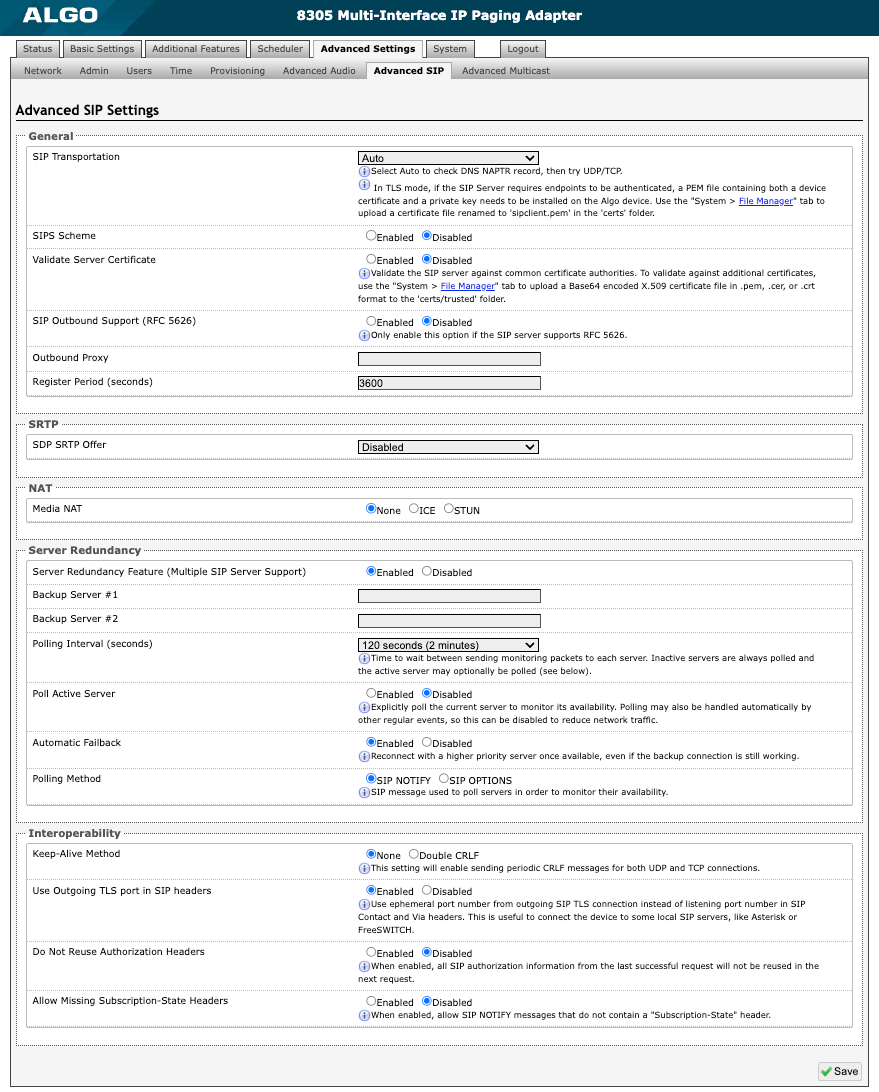
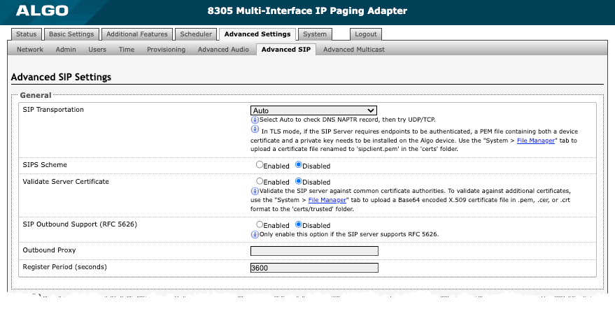
Figure 8: Configure Advanced SIP settings.
General
| |
SIP Transportation | Select a transport layer protocol to use for SIP messages from the dropdown. These options include:
|
SIPS Scheme | Only visible when SIP Transportation is set to TLS. Enable to require the SIP connection from endpoint to endpoint to be secure. |
Validate Server Certificate | Enable to validate the SIP server against common certificate authorities. To validate additional certificates, navigate to System → File Manager to upload a Base64 encoded X.509 certificate file in .pem, .cer, or .crt format to the certs folder. |
SIP Outbound Support (RFC 5626) | Enable this option to support best networking practices according to RFC 5626. This option should be enabled if the 8305 is registered with a hosted server or TLS is used for SIP Transportation. |
Outbound Proxy | Enter the IP address for an outbound proxy. |
Register Period (seconds) | Enter the maximum requested period where the 8305 will re-register with the SIP server. The default setting is 3600 seconds (1 hour). Note that if an Expires header is provided by the SIP response 200 (OK), this time will take precedence over the Register Period defined time here. Only change if instructed to do so. |
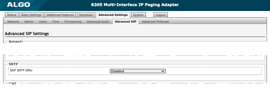
SRTP
| |
SDP SRTP Offer | Select an option from the dropdown menu:
|
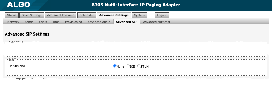
NAT
| |
Media NAT | IP address for STUN server if present or IP address/credentials for a TURN server. |
ICE – TURN Server | Enter the IP address or domain of the ICE server. |
ICE – TURN User | Enter the username. |
ICE – TURN Password | Enter the password. |
STUN - Server | Enter the IP address or domain of the STUN server. |
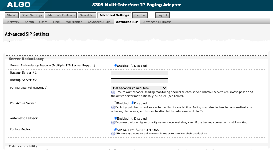
Server Redundancy
| |
Server Redundancy Feature | Enable to configure up to two secondary backup servers. When enabled, the 8305 will attempt to register with the primary server but switch to a secondary server when necessary. The configuration allows re-registration to the primary server upon availability or to stay with a server until unresponsive. |
Backup Server #1, #2 | Provided by your SIP provider or IT team. |
Polling Intervals (seconds) | Select the time interval for sending monitoring packets to each server from the dropdown menu. Inactive servers are always polled and the active server may optionally be polled. |
Poll Active Server | Enable to explicitly poll the current server to monitor availability. Other regular events may also handle this automatically and can be disabled to reduce network traffic. |
Automatic Fallback | Enable to allow the 8305 to reconnect with a higher priority server once available, even if the backup connection is still working. |
Polling Method | Select a polling method based on what your SIP provider supports. |
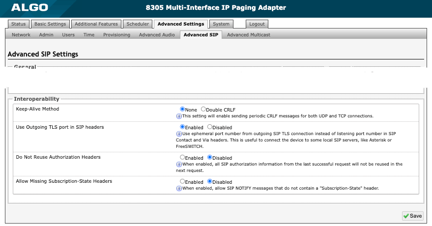
Interoperability
| |
Keep-Alive Method | Select a keep-alive method:
|
Keep-Alive Interval | Set the interval in seconds that the CRLF message should be sent. 30 seconds is recommended. |
Use Outgoing TLS port in SIP Headers | Enable to use the ephemeral port number from an outgoing SIP TLS connection instead of the listening port number in SIP Contact and Via headers. This is useful for connecting the device to some local SIP servers, like Asterisk or FreeSWITCH. |
Do Not Reuse Authorization Headers | Enable so all SIP authorization information from the last successful request will not be reused in the next request. |
Allow Missing Subscription-State Headers | Enable to allow SIP NOTIFY messages that do not contain a ‘Subscription-State’ header. |
Multicast Configuration
The 8305 Multi-Interface IP Paging Adapter can be programmed as a multicast transmitter or receiver. As a paging adapter designed to emulate an analog telephone connection, the ability to multicast allows you to scale communications you are already making in a simple and effective way. IP endpoints connected to the 8305 can be grouped into up to 50 multicast zones and paged via DTMF Selectable Mode or multiple SIP extensions.
Dual-tone multi-frequency (DTMF) refers to the sounds or tones a telephone generates when the numbers are pressed. To page with DTMF Selectable Mode, a user can dial the SIP extension of the transmitter device and dial the desired DTMF page zone (e.g., 1, 2, etc.) on the keypad.
Another way to page multiple zones with the 8305 is through multiple registered SIP extensions on the transmitter device. Each extension is mapped to a unique zone, allowing zones to be called directly.
Multicast IP Addresses
Each 8305 has a unique IP address and shares a common multicast IP and port number (multicast zone) for multicast packets. The Transmitter units send to a configurable multicast zone, and the Receiver units listen to assigned multicast zones.
The network switches and router see the packet and deliver it to all the group members. The multicast IP and port number must be the same on all one group's Transmitter and Receiver units. The user may define multiple zones by picking different multicast IP addresses and/or port numbers.
Multicast IP addresses range: 224.0.0.0/4 (from 224.0.0.0 to 239.255.255.255)
Port numbers range: from 1 to 65535
By default, the 8305 is set to use the multicast IP address 224.0.2.60 and the port numbers 50000-50008
Ensure the multicast IP address and port number do not conflict with other services and devices on the same network.
Enable Multicast Streaming
The 8305 Multi-Interface IP Paging Adapter multicast features only require the first endpoint be registered as a SIP extension. If only one audio stream is active at any given time, additional Algo IP Endpoints, including any combination of paging adapters, speakers, and visual alerters, may be added as multicast receivers. If multiple unique audio streams are needed simultaneously, more than one transmitter will be required.
The Algo IP endpoint configured as the transmitter will stream audio to the receivers simultaneously. Receiver endpoints do not require SIP extensions and do not need to register with the SIP Communication Server.
To enable multicast streaming from the transmitter adapter, open the web interface and go to the Basic Settings → Multicast tab. For Multicast Mode, select Transmitter (Sender). For Transmitter Single Zone, select All Call.
To enable multicast monitoring of the receiver endpoints, go to the web interface for each endpoint and navigate to the Basic Settings → Multicast tab. For Multicast Mode, select Receiver (Listener). There is no need to select a Transmitter Single Zone. The endpoint will monitor the All Call zone IP address by default.
The page pre-announce tone is generated from the transmitter. The speaker volume can be increased or decreased for each multicast receiver individually.
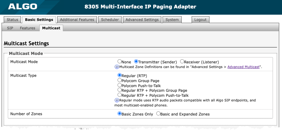
Multicast: Transmitter (Sender)
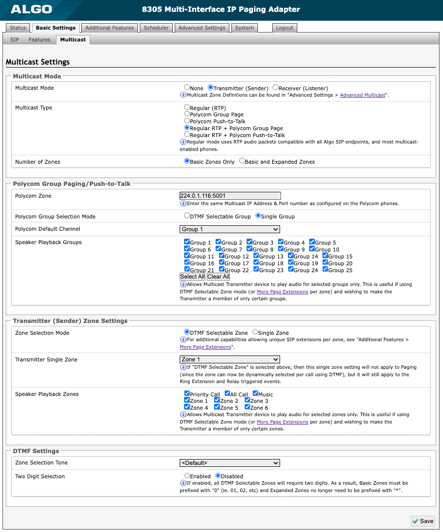
Figure 9: Multicast transmitter mode settings.
Multicast Mode Always ensure that the multicast settings on all Receiver devices match those of the Transmitter.
| |
Multicast Mode | If Transmitter (Sender) is selected, the 8305 will broadcast an IP stream when activated in addition to playing audio through the audio output. The 8305 cannot be both a multicast Transmitter and Receiver simultaneously. |
Multicast Type | The 8305 may broadcast multicast paging compatible with Poly “on-premise group paging” protocol and most multicast-enabled phones that use RTP audio packets. Select Regular (RTP) if you are only multicasting to Algo IP endpoints or multicast-enabled phones. To multicast page announcements to Poly phones, select Poly Group Page or Poly Push-to-Talk. Select Regular RTP + Poly Group Page or Regular RTP + Push-to-Talk to multicast page audio to Poly phones, Algo IP endpoints, and multicast-enabled phones. |
Number of Zones | Select Basic Zones Only if configuring nine or fewer multicast zones. Select Basic and Expanded Zones to configure up to 50 zones. The expanded zones have the same behavior as the basic Receiver zones but are hidden by default to simplify the interface. |
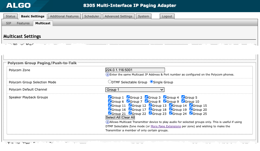
Poly Group Paging/Push-to-Talk This section is used if the Multicast Type includes Poly Group Page or Poly Push-to-Talk.
| |
Poly Zone | Enter the same Multicast IP Address and Port number configured on the Poly phones. |
Poly Group Selection Mode | Select Single Group to broadcast on one pre-configured group. Multiple SIP extensions can be registered on the Transmitter device. Each extension is mapped to a unique group, allowing groups to be called directly (e.g., from speed-dial keys). See Additional Features → More Page Extensions for additional configuration settings. If DTMF Selectable Group is selected, the group is determined by the DTMF selection between 0 – 25. To page using DTMF Selectable Zone:
DTMF group definitions include:
…
All DTMF codes and respective zones are available in Advanced Settings → Advanced Multicast. |
Poly Default Channel | Select the default group for the multicast stream to be sent to. If DTMF Selectable Group is chosen, this single group setting will not apply to paging since the group will be dynamically selected per call using DTMF. The Single Group setting will still apply to the ring extension and relay triggered events. The Poly Default Channel is the default channel used for multicast actions unless an option is available for a custom channel with specific parameters. |
Speaker Playback Groups | Select Speaker Playback Groups to control which specific groups can play audio from the device. This is useful if using the DTMF Selectable Group mode or additional page extensions (Additional Features → More Page Extensions) per group to make 8305 a member of only certain zones. In this case, the Transmitter does not participate in the Zone but transmits certain traffic. |
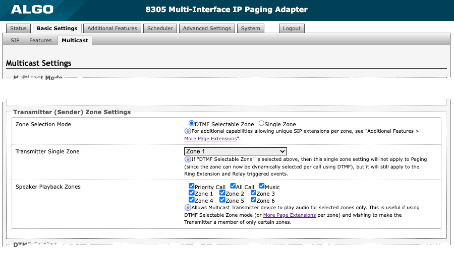
Transmitter (Sender) Zone Settings This section is used if the Multicast Type includes Regular (RTP).
| |
Zone Selection Mode | Select Single Zone to broadcast on one pre-configured zone. Multiple SIP extensions can be registered on the Transmitter device. Each extension is mapped to a unique zone, allowing zones to be called directly (e.g., from speed-dial keys). See Additional Features → More Page Extensions for additional configuration settings. If DTMF Selectable Zone is selected, the zone is determined by the DTMF selection between 0 – 50. Once multicast Transmitter mode is enabled, navigate to Advanced Settings → Advanced Multicast to find the DTMF codes corresponding to each zone. To page using DTMF Selectable Zone:
DTMF zone definitions include:
All DTMF codes and respective zones are available in Advanced Settings → Advanced Multicast. |
Transmitter Single Zone | Select the default zone for the multicast stream to be sent to. If DTMF Selectable Zone is chosen, this single zone setting will not apply to Paging since the zone will be dynamically selected per call using DTMF. However, this single zone setting will still apply to the ring extension and relay triggered events. The Transmitter Single Zone is the default zone used for multicast actions unless an option is available for a custom zone with specific parameters. |
Speaker Playback Zones | Select Speaker Playback Zones to control which specific zones the 8305 can play audio. This is useful if using the DTMF Selectable Zone mode or additional page extensions (Additional Features → More Page Extensions) per zone to make 8305 a member of only certain zones. In this case, the Transmitter does not participate in the Zone but transmits certain traffic. |
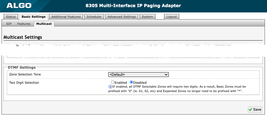
DTMF Settings
| |
Zone Selection Tone | Select a tone to be played to prompt a user to select a zone to multicast to. This may be used as an interactive voice response (IVR) menu by uploading a custom audio file in the tones folder through System → File Manager. Each zone may use a different tone. This can be configured in Advanced Settings → Advanced Multicast. |
Two-Digit Selection | When enabled, all DTMF Selectable Zones will require two digits. As a result, Basic Zones must be prefixed with 0, and Expanded Zones will no longer need to be prefixed with *. |
Multicast: Receiver (Listener)
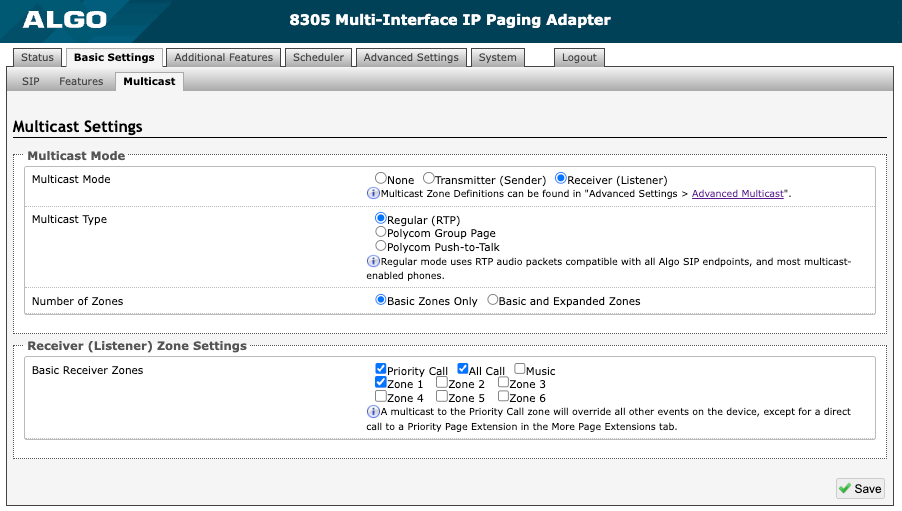
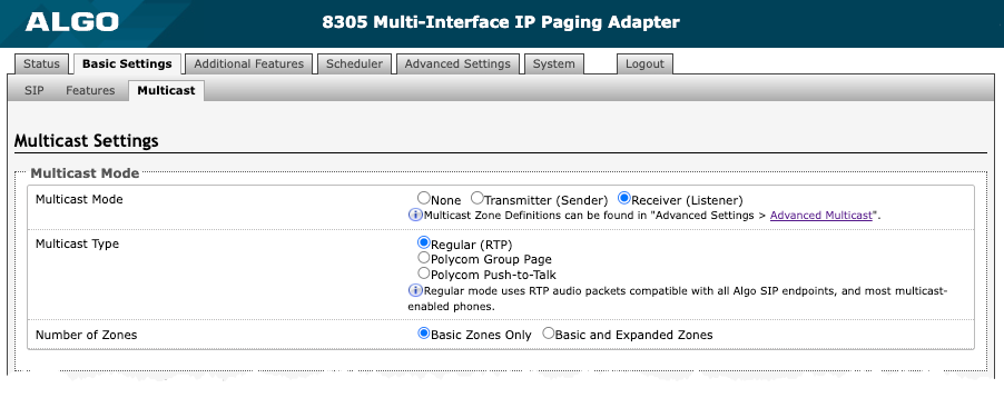
Figure 10: Multicast receiver mode settings.
Multicast Mode Always ensure that the multicast settings on all Receiver devices match those of the Transmitter.
| |
Multicast Mode | If Receiver (Listener) mode is selected, the 8305 will activate when receiving a multicast message. It will mimic the audio stream of the transmitter but use local volume settings. This can be set via Basic Settings → Features → Page Speaker Volume. |
Multicast Type | Select Regular if receiving multicast from other Algo IP endpoint(s) and/or multicast-enabled phone(s) that use RTP audio packets. Select Poly Group Page or Poly Push-to-Talk if receiving multicast paging compatible with Poly “on-premise group paging” protocol. |
Number of Zones | Select Basic Zones Only if configuring nine or fewer multicast zones. Select Basic and Expanded Zones to configure up to 50 zones. The expanded zones have the same behavior as the basic Receiver zones but are hidden by default to simplify the interface. |
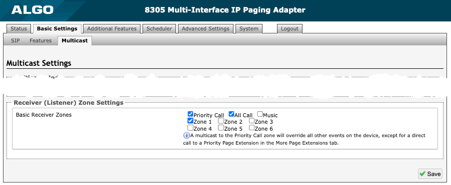
Receiver (Listener) Zone Settings
| |
Basic Receiver Zones | Select one or more multicast zones for the 8305 to listen to. Multicast zone priority will be based on the zone definition list order defined in Advanced Settings → Advanced Multicast. |
Expanded Receiver Zones | Select additional zones (up to 50) for the device to listen to. This is only possible when Basic and Expanded Zones is selected. |
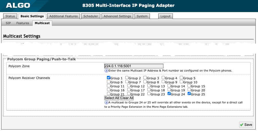
Poly Group Paging/Push-to-Talk
| |
Poly Zone | Enter the Poly Zone (IP Address and Port) that matches the configuration of the Poly phones and Channels. |
Poly Receiver Channels | If using a Poly telephone as a Multicast Transmitter, a tone may be set for any of the 25 Poly Groups configured on the 8305. Poly Group Tones can be set in Advanced Settings → Advanced Multicast. The Poly telephone used as page audio source for the 8305 must be configured to use either the G.711 or G.722 audio codec. Note that Poly phone(s) must be configured with the “Compatibility” setting (“ptt.compatibilityMode”) disabled for this codec setting to be applied. |
Using Multicast Page Zones
The 8305 Multi-Interface IP Paging Adapter can listen to nine basic multicast zones; however, up to 50 are available (See Additional Features → More Page Extensions for more details). The multicast IP addresses define these zones.
By default these zones have the names below but can be used however you prefer. When set as a multicast receiver, zones have a priority hierarchy where zones higher on the list will be treated with higher priority, with Music being the lowest priority. When set as a multicast transmitter, event priority is based on the event type that initiated the multicast rather than the output multicast channel that will be active.
Priority
All Call
Zone 1
Zone 2
Zone 3
Zone 4
Zone 5
Zone 6
Music
There are two options for paging to multiple zones:
DTMF Selectable Mode: Has a dynamic page zone selection and requires only the transmitting device to have a registered SIP extension. To page, dial the SIP extension of the transmitter and dial the desired DTMF page zone (e.g., 1, 2, etc.) on the keypad. DTMF digits and their corresponding zone numbers can be found in the Advanced Settings → Advanced Multicast tab of the 8305 web interface.
Multiple page extensions: Multiple SIP extensions can be registered on the transmitter. Each extension is mapped to a unique zone, allowing zones to be called directly. See Additional Features → More Page Extensions tab of the 8305 web interface for more details.
Advanced Multicast
These settings are only visible when in Transmitter or Receiver multicast mode. This can be set in Basic Settings → Multicast. The default, pre-populated multicast zone IP addresses and ports will work in most cases and should only be altered in rare cases.
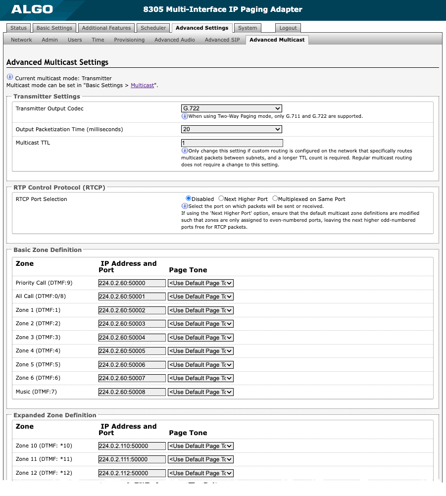
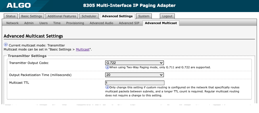
Figure 12: Advanced multicast - transmitter settings.
Transmitter Settings
| |
Transmitter Output Codec | Select an audio encoding format for the Transmitter device to use when sending output to the Receivers. Supported formats include:
Only G.711 and G.722 are supported when using Two-Way Paging mode. |
Output Packetization Time (milliseconds) | Select the size of the audio packets the Transmitter sends to the Receivers from the dropdown menu. The default of 20 milliseconds is recommended unless a different value is specifically required for compatibility with other devices. |
Multicast TTL | Only change the multicast time to live (TTL) setting if custom routing is configured on the network that specifically routes multicast packets between subnets and a longer TTL count is required. This ensures packets are not bounced back and forth in a network identity. When the TTL is reached, the router drops the packet. |
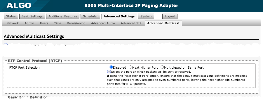
RTP Control Protocol (RTCP)
| |
RTCP Port Selection | Select how a port will be chosen to send or receive RTCP packets. Note: If Next Higher Port is selected, ensure that the default multicast zone definitions are modified so that zones are only assigned to even-numbered ports, leaving the next higher odd-numbered ports free for RTCP packets. |
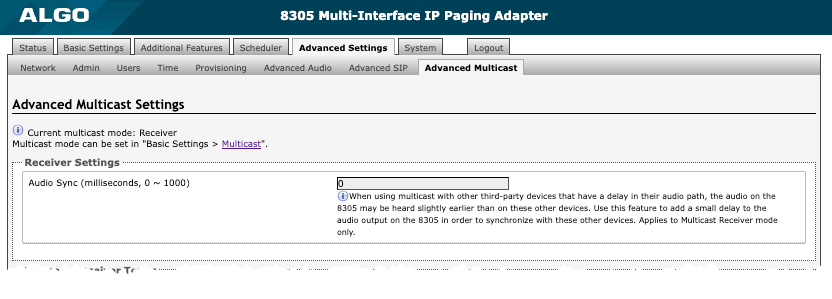
Receiver Settings
| |
Audio Sync | Available if under Basic Settings → Multicast the Multicast Mode is set to Receiver (Listener) and Multicast Type is set to Poly Group Page or Poly Push-to-Talk. When using multicast with other third-party devices that have a delay in their audio path, the audio on the 8305 may be heard slightly earlier than on these other devices. Use this feature to add a small delay to the audio output on the 8305 to synchronize with these other devices. |
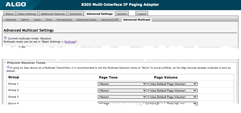
Poly Receiver Tones
| |
Poly Receiver Tones | Available if under Basic Settings → Multicast the Multicast Mode is set to Receiver (Listener) and Multicast Type is set to Poly Group Page or Poly Push-to-Talk. A tone may be set for any of the 25 Poly Groups. If using an Algo device as a Multicast Transmitter, it is recommended to set the Receiver tones to None to avoid conflicts, as the Algo devices already multicast a tone by default. |
Audio Configuration
In addition to voice paging, the 8305 Multi-Interface IP Paging Adapter can play audio files for emergency, safety, security announcements, customer service, shift changes, etc. Audio files can be stored on the adapter and played over a speaker in response to an event such as a ring, relay input, or automated schedule.
An emergency notification system is essential for delivering critical messages in seconds to those within your facility. The 8305 can also be connected to a visual alerter, such as a strobe light, to accompany audio emergency notifications.
Basic Audio Settings
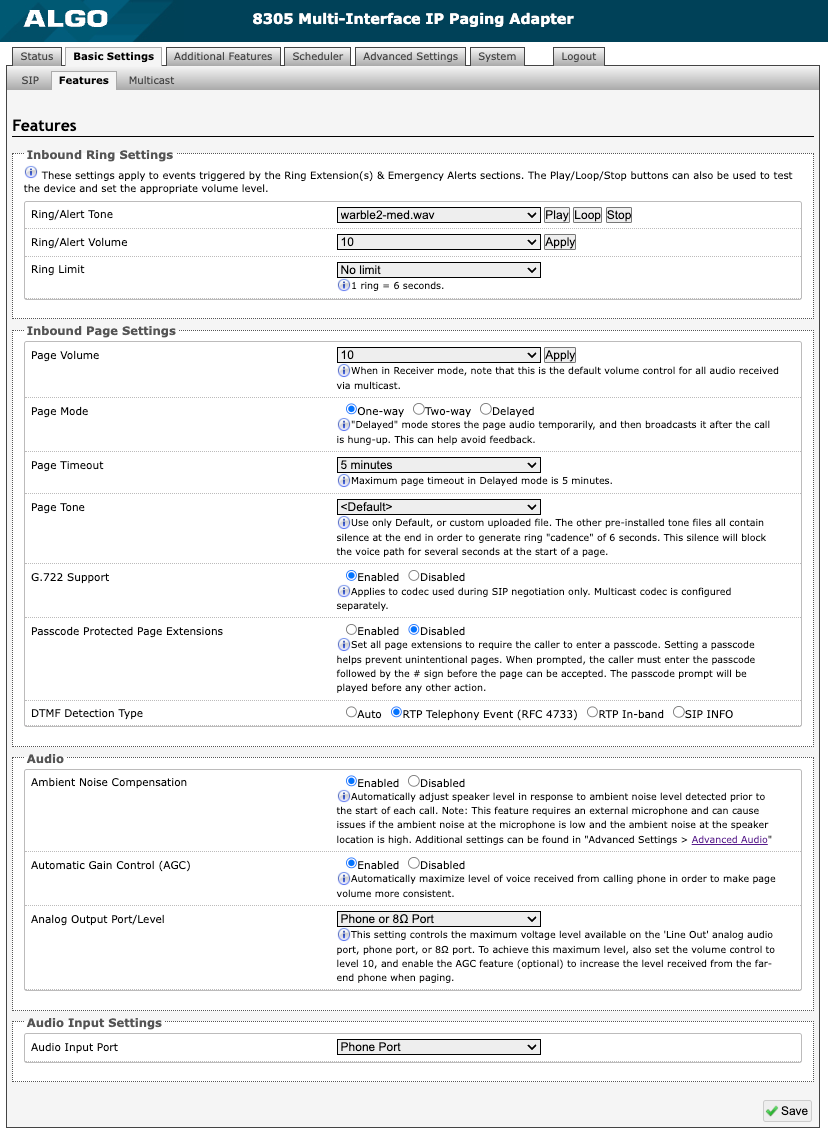
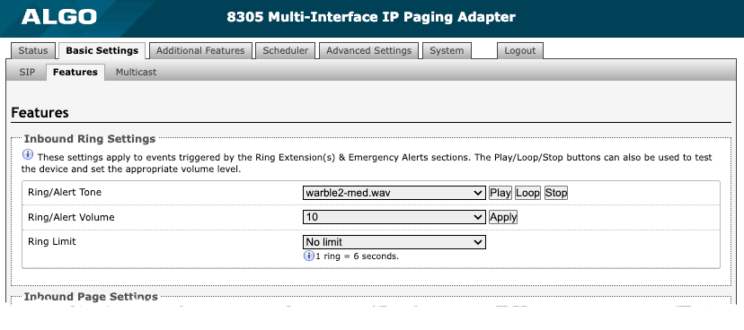
Figure 14: Basic Settings → Features.
Inbound Ring Settings Ring settings apply to events triggered by Ring Extensions and Emergency Alerts. Emergency Alert tones are configured under Additional Features → Emergency Alerts.
| |
Ring/Alert Tone | Select an audio file to play when a ring event is detected on the SIP Ring Extension. Test the audio file immediately using the Play, Loop, and Stop buttons if the 8305 is connected to a speaker. During multicast, the device will broadcast an audio stream using the Transmitter’s selected ringtone. This is the default tone that will be played if selected in the settings Multicast → Additional Ring Extension. |
Ring/Alert Volume |
See Page Speaker Volume below for multicast settings. |
Ring Limit | Typically set to no limit. Ring Limit will limit how long the speaker will ring before timing out. A new ring event must occur for the speaker to play the audio file again. |
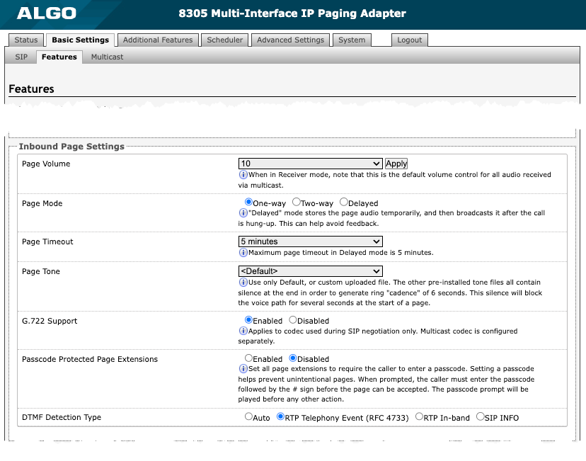
Inbound Page Settings
| |
Page Volume |
|
Page Mode | Set calls to the SIP page extension as one-way, two-way (using an external microphone), or delayed. In delayed mode, the speaker will record a message to be played after disconnecting. The device will buffer an announcement up to 5 minutes long. To cancel a page while in delay mode, press “*” while recording to prevent it from being sent after hanging up. |
Page Timeout | Set the maximum duration for a page. The page will end when the timeout limit has been reached. This is useful to ensure the paging system is not stuck in an active state in cases where someone accidentally forgets to hang up. |
Page Tone | Select a pre-page tone to be played when a page is starting. Use only the Default or custom uploaded files. Other pre-installed tone files contain silence at the end to generate a ring "cadence" of 6 seconds. This silence will block the voice path for several seconds at the start of a page. The “Default” tone is set to page-notif.wav. The Default Page Tone in Advanced Multicast will play the tone set here. |
G.722 Support | Enable or disable the G.722 codec. G.722 enables wideband audio for optimum speech intelligibility. |
Passcode Protected Page Extensions | When enabled, the caller must enter the set passcode followed by the # sign before the page can be made. Setting a passcode helps prevent unintentional pages. |
Apply to All Page Extensions | Only visible when Passcode Protected Page Extensions is set to Enabled. Enable or disable a passcode for all page extensions. |
Passcode | Only visible when Passcode Protected Page Extensions is set to Enabled. Passcodes can be up to 15 digits and must be numbers only. |
Passcode Prompt Tone | Only visible when Passcode Protected Page Extensions is set to Enabled. Select the tone to be played to prompt the user to enter the passcode before paging. |
DTMF Detection Type | Select the preferred dual-tone multi-frequency (DTMF) detection method. DTMF is a technology used with touch tone phones (the sound made when pressing a number key). The 8305 uses this for multi-zone selection, passcode, etc. |
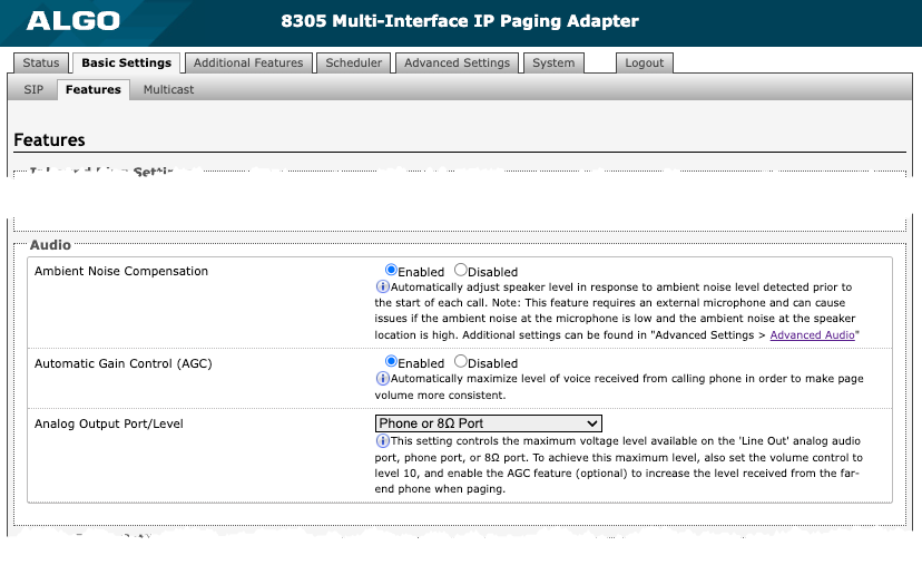
Audio
| |
Ambient Noise Compensation | When enabled, Ambient Noise Compensation will allow the speaker level to adjust automatically in response to ambient noise levels detected at the device before the start of each call. The 8305 requires an external microphone to be connected to do this. |
Automatic Gain Control (AGC) | Enable or disable AGC to normalize the audio level. Enabling ensures the speaker is always played at a consistent volume. |
Analog Output Port/Level | Set the maximum voltage level available on the 'Line Out' analog audio port, telephone port, or 8Ω port. To achieve the maximum level, also set the volume control to level 10 and enable the Automatic Gain Control (AGC) to increase the level received from the far-end telephone when paging. |
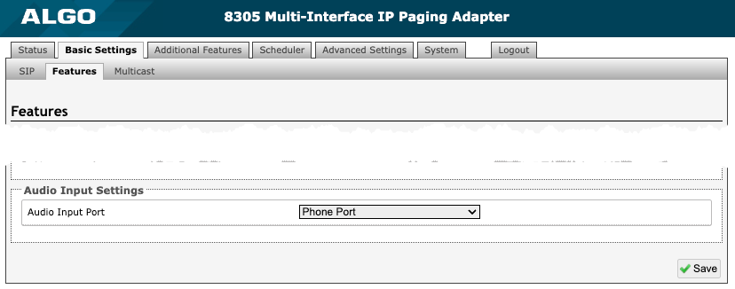
Audio Input Settings
| |
Audio Input Port | Select telephone Port or Aux Out to choose where audio will be played to. |
Tones
The 8305 includes several pre-loaded audio files that can be selected to play for various events. The web interface allows you to select a file and play it immediately over the speaker for testing, available in Basic Settings → Features. Files may also be added, deleted, or renamed.
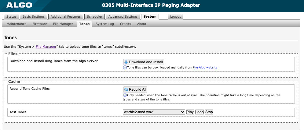
Figure 16: Tones settings
Related Links:
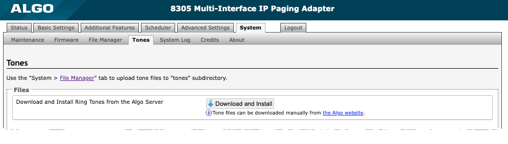
Files
| |
Download and Install Ring Tones from the Algo Server | Tone files can be downloaded manually from the Algo website. |
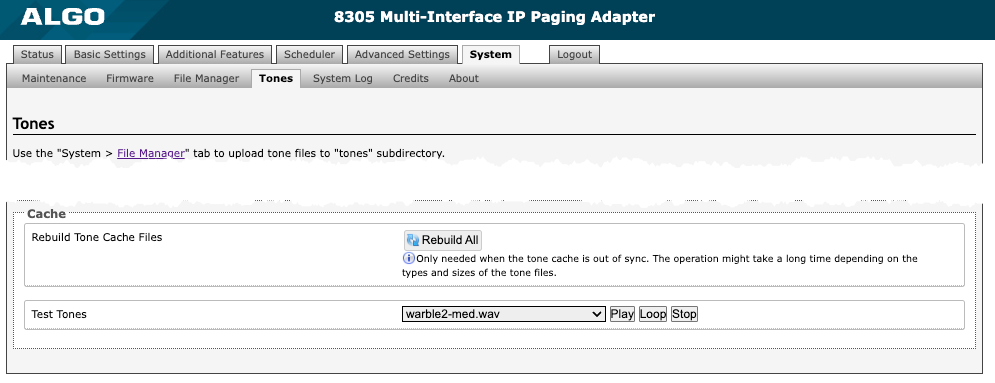
Cache
| |
Rebuild Tone Cache Files | Only needed when the tone cache is out of sync. The operation might take a long time depending on the types and sizes of the tone files. |
Test Tones | Listen to uploaded audio files before selecting them for your system. |
Advanced Audio
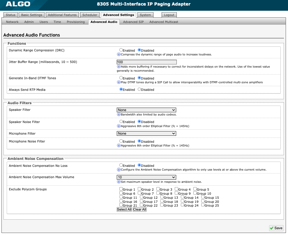
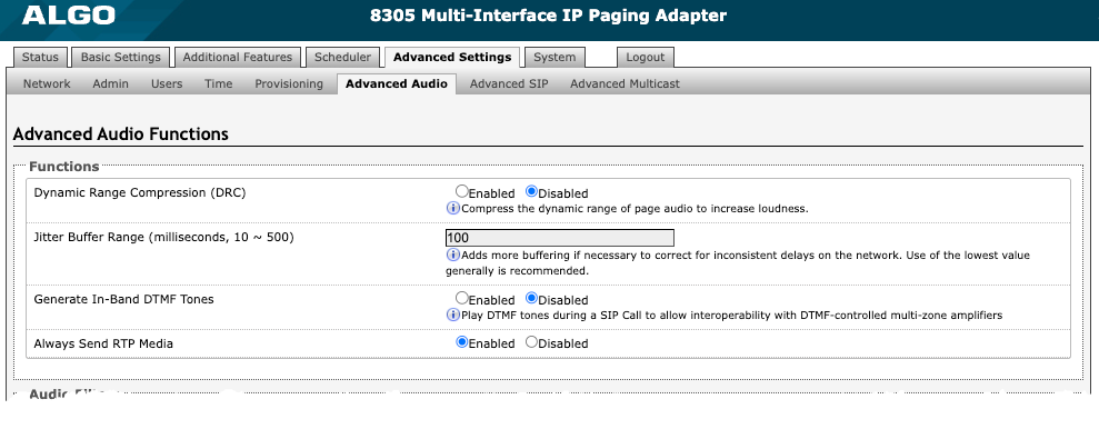
Figure 18: Advanced audio settings.
Functions
| |
Dynamic Range Compression (DRC) | Enable to compress the dynamic range of page audio to increase loudness. |
Dynamic Range Compression Gain | Select the amount of compression gain from the dropdown menu. More gain increases distortion. |
Jitter Buffer Range | Enter a value between 10-500 to add more buffering if necessary to correct for inconsistent delays on the network. It is recommended to use the lowest value. |
Generate In-Band DTMF Tones | Enable to play DTMF tones during an SIP call to allow interoperability with DTMF-controlled multi-zone legacy communication systems. |
Always Send RTP Media | Enable to send audio packets at all times, even during one-way paging mode. This option is needed when the server expects to always see audio packets. |
Audio Filters
| |
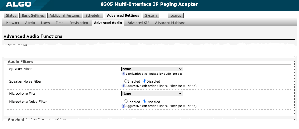
Speaker Filter | Select a frequency from the dropdown to apply a high-pass filter to the speaker output. This setting reduces audio artifacts like humming or buzzing by filtering out unwanted frequencies. |
Speaker Noise Filter | Enable to filter below 145 Hz to reduce mains-induced noise like fans. |
Microphone Filter | Select a frequency from the dropdown to apply a high-pass filter to the microphone input. This setting reduces audio artifacts like humming or buzzing by filtering out unwanted frequencies. |
Microphone Noise Filter | Enable to filter below 145 Hz to reduce mains-induced noise like fans. |
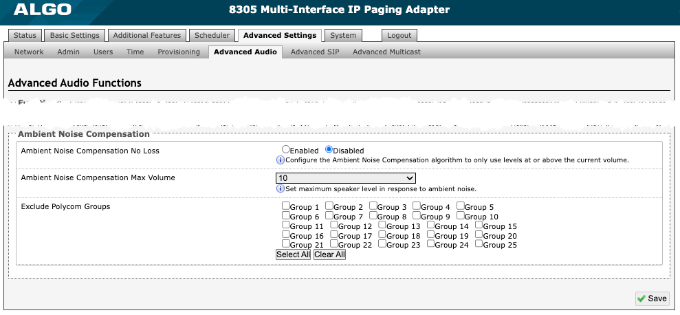
Ambient Noise Compensation Only available if Ambient Noise Compensation is Enabled in Basic Settings → Features.
| |
Ambient Noise Compensation No Loss | Configure the Ambient Noise Compensation algorithm to only use levels at or above the current volume. The current volume is the minimum volume when this setting is enabled. |
Ambient Noise Compensation Max Volume |
|
Schedule Configuration
The 8305 includes a calendaring functionality synchronized to Network Time Protocol (NTP). It can schedule school bells, play automated announcements for retail and healthcare, and notify workplace shift changes and breaks.
Calendar events can be scheduled to play in specific zones, allowing the delivery of announcements to part or all of a facility. This feature is most applicable in education or manufacturing environments where specific building areas (e.g., classrooms or production floors) may need regular bell schedules and announcements, while other areas may not require ongoing messages.
Calendar
The Calendar displays scheduled events like bells and announcements. These can include events deployed with Algo IP speakers, paging adapters, and visual alerters.

Figure 19. Calendar on the Schedules tab of the 8305 web interface.
After an event is created in the Schedules tab (see next section), you can add it to the calendar view by clicking the dropdown menu at the top right of the calendar.
To set a single date for your event, click on Single and then the date you would like the event to be played. Click Save to save your schedule.
To set a recurring schedule, click on Recurring then set the parameters at the bottom of the calendar. Once these are set, click on the date on the calendar that you want your recurring schedule to start. Click Save to save your schedule.
If you would like to remove a schedule, click None (clear) in the dropdown menu, then click on the schedule in the calendar you want to remove. Click Save to save your changes.
Schedules
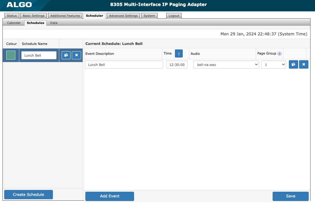
Figure 20. Setting up a schedule for the 8305 in the web interface.
The Schedules tab is used to set and configure events such as preset pages, announcements, or notifications.
To create a schedule, click Create Schedule. Enter a Schedule Name and select a Colour to represent the schedule in the calendar.
To add an event to a schedule, select the schedule you want to modify and click Add Event at the bottom of the interface. Add an Event Description, Time, and Audio. If your device is set to Multicast Transmitter, you should also set the Page Zone. The selected audio file will be played locally over the network via multicast to Algo endpoints or RTP multicast compatible third-party equipment configured as Receivers in this zone.
Once a schedule has been configured, it can be added to the desired dates on the Calendar. Up to 30 different schedules can be created. For example, Fridays might have a different schedule than the other weekdays. Each schedule may contain up to 500 events.
.png) Delete schedule or event button
Delete schedule or event button.png) Copy event button
Copy event button
Data
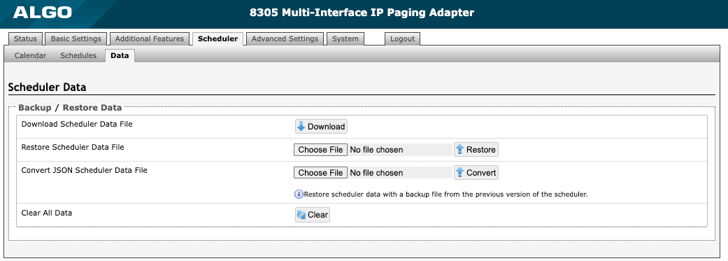
Figure 21. Configuring the Scheduler → Data tab.
Backup/Restore Data | |
Download Scheduler Data File | Download a backup database file of schedules with events, times, and calendar dates. Note that this backup is independent from the rest of the configuration backup on the device. |
Restore Scheduler Data File | Upload and restore a saved Scheduler data file. |
Convert JSON Scheduler Data File | If you are migrating from old firmware and would like to restore your data to a newer device, you may upload the JSON file from your old system here. |
Clear All Data | Clear all the Scheduler data including saved schedules and set calendar dates. |
Integration
Input/Output
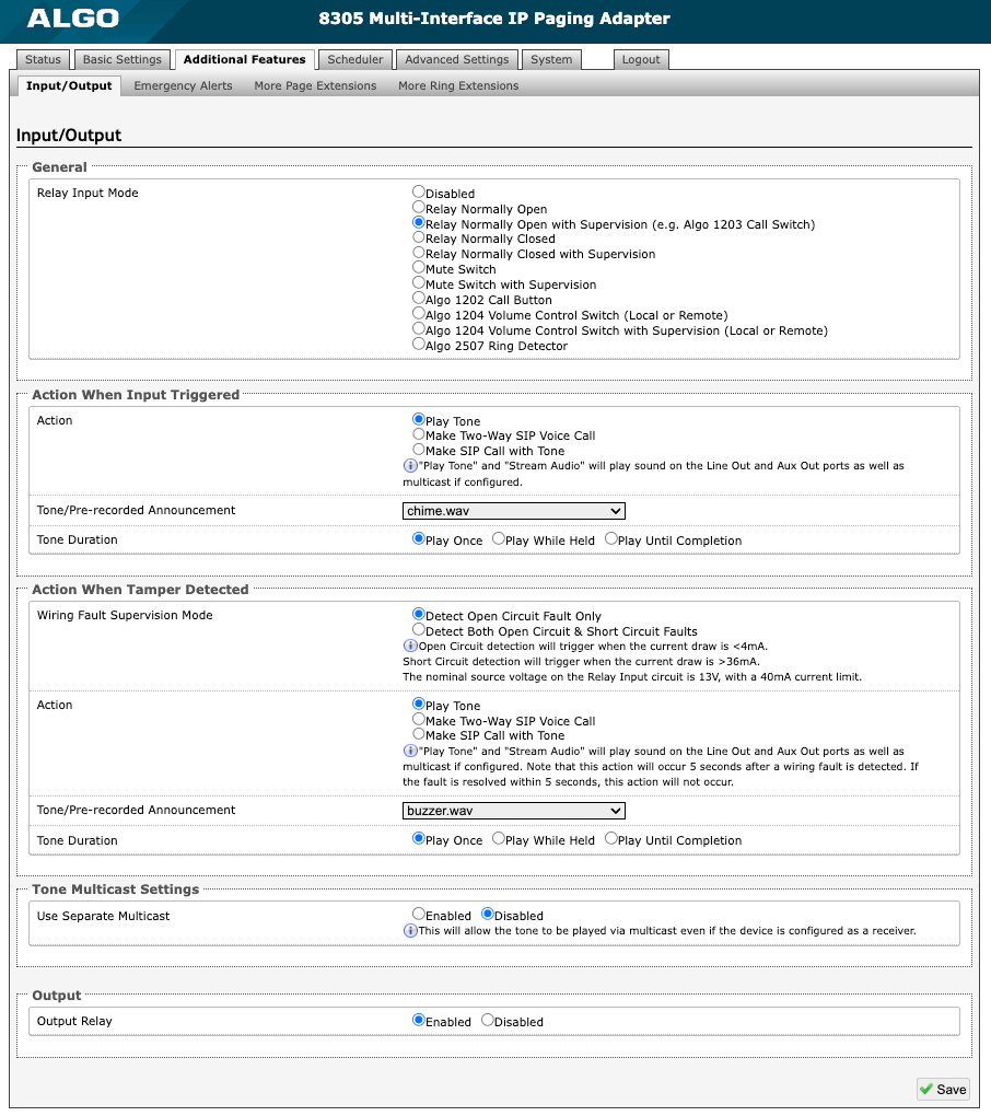
Figure 13: Input settings.
General
| |
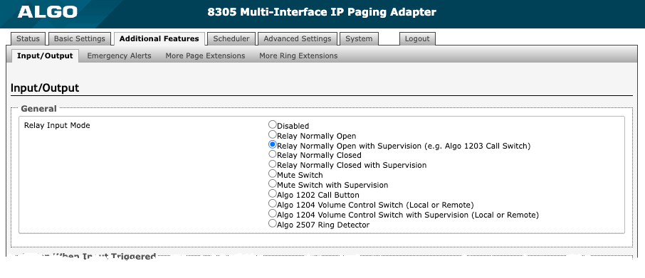
Relay Input Mode | The 8305 has dry contact input terminals to connect external accessories, including Algo and third-party accessories. Options for Relay Input Mode include:
Notification actions can be triggered via supervision settings if the input switch is disconnected. For more information on how to configure each of these devices with the 8305, see Algo Compatible Accessories. |
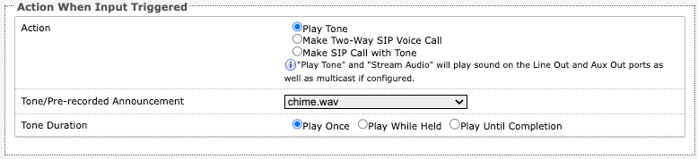
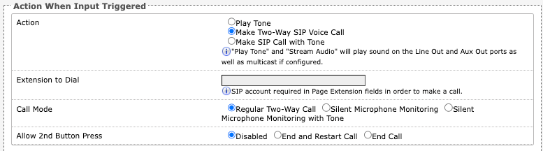
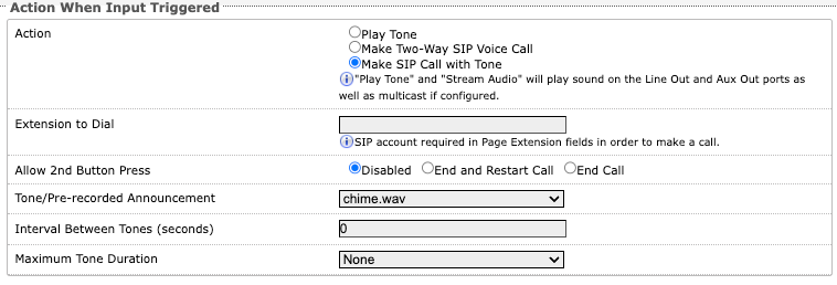
Action When Input Triggered | |
Action | Play Tone
Make Two-Way SIP Voice Call
Make SIP Call with Tone
|
Tone/Pre-recorded Announcement | Available when Action is set to Play Tone or Make SIP Call with Tone.
|
Tone Duration | Available when Action is set to Play Tone. |
Extension to Dial | Available when Action is set to Make Two-Way SIP Voice Call or Make SIP Call with Tone. A SIP account is required in Page Extension fields to make a call. |
Call Mode | Available when Action is set to Make Two-Way SIP Voice Call. |
Allow 2nd Button Press | Available when Action is set to Make Two-Way SIP Voice Call or Make SIP Call with Tone. If enabled, the 2nd button press will End Call or End and Restart Call. Therefore, if an input is triggered a second time, the SIP call will be terminated and, in some cases, immediately called again. |
Interval Between Tones | Available when Action is set to Make SIP Call with Tone. Specify the time delay (seconds) between tones. |
Maximum Tone Duration | Available when Action is set to Make SIP Call with Tone. Select the maximum tone duration. The tone will be terminated once the maximum time is reached. |
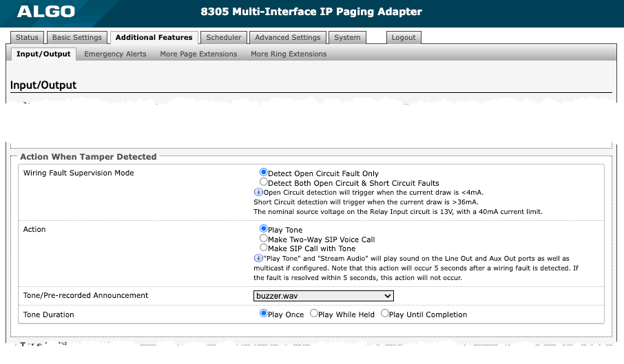
Action When Tamper Detected 8305 can be configured with supervision to execute one of the above three actions (Play Tone, Make Two-Way SIP Voice Call, Make SIP Call with Tone) if the device goes offline due to wiring failure or after being tampered with. For example, a tone could sound over the speaker(s) or a private pre-recorded message could be sent to a specified telephone extension. The supervision configuration options will appear if a Relay Input Mode with supervision is selected. See “Action When Input Triggered” above for information on additional settings.
| |
Wiring Fault Supervision Mode | Short circuit detection will be triggered when the current draw is <4 mA. Short circuit detection will trigger when the current draw is >36 mA. The nominal source voltage on the Relay Input circuit is 13 V with a 40 mA current limit. |
Action | Play Tone Make Two-Way SIP Voice Call Make SIP Call with Tone |
Tone/Pre-recorded Announcement | Available when Action is set to Play Tone or Make SIP Call with Tone. Select a recording or tone to use. Custom audio files may be used and uploaded through System → File Manager. |
Tone Duration | Available when Action is set to Play Tone. |
Ring Detection | |
|---|---|
Action | Set what happens when a ring is detected:
|
Extension to Dial | Specifies the SIP extension to dial. |
Interval Between Tones (seconds) | Specifies the pause time before the tone plays again. |
Maximum Tone Duration | Specifies the maximum time the tone plays. |
Tone/Pre-recorded Announcement | Select a tone to play when a ring is detected. |
Tone Duration | Select how long the tone should play:
|
.png)
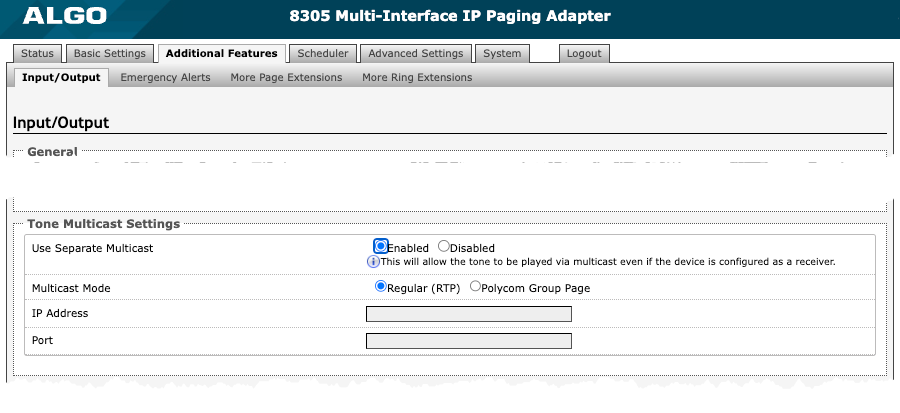
Tone Multicast Settings
| |
Use Separate Multicast | When enabled, the set tone will be played via multicast even if the 8305 is configured as a receiver. See additional options when enabled. |
Multicast Mode | Use the same details as the receiver zone that is being listened to. |
IP Address | Use the same details as the receiver zone that is being listened to. |
Port | Use the same details as the receiver zone that is being listened to. |
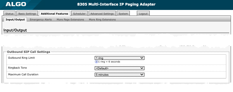
Outbound SIP Call Settings
| |
Outbound Ring Limit | Available when Action is set to Make Two-Way SIP Voice Call or Make SIP Call with Tone. Select the number of rings that will occur before the call reaches voicemail. One ring is six seconds. |
Ringback Tone | Available when Action is set to Make Two-Way SIP Voice Call. Select a ringback tone to play during an outbound SIP call while waiting for the far-end party to answer. |
Maximum Call Duration | Available when Action is set to Make Two-Way SIP Voice Call. |
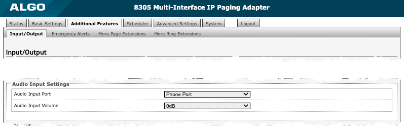
Audio Input Settings
| |
Audio Input Port | Select the input port your device is connected to. |
Audio Input Volume | Set the desired input volume. |
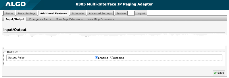
Output
| |
Output Relay | Enable to close the circuit when you attempt to trigger events elsewhere. This setting controls whether the output relay activates or not. Note that when enabled, the output relay will activate whenever the 8305 is activated (paging, alerting, etc.) This is a normally open relay only. |
API
Algo RESTful API can be used to access, manipulate, and trigger Algo endpoints on your network through HTTP/HTTPS requests.
Requesting systems can interact with Algo devices through a uniform and predefined set of stateless operations. See the Algo RESTful API Guide for more details.
To configure API settings on your 8305 Multi-Interface IP Paging Adapter, use the web interface and navigate to Advanced Settings → Admin → API Support.
API Support
| |
RESTful API | Enable a secure API for remote access and device control via HTTP. For more information, see the Algo RESTful API Guide. |
Authentication Method | Speak to your IT Administrator for more information. |
RESTful API Password | Speak to your IT Administrator for more information. |

| |
SCI | Simple Control Interface (SCI) is a separate control interface for certain applications. Its primary purpose is to support phones that may have programmable keys that can only send out HTTP GET requests. |

InformaCast
As a Singlewire Solutions Partner, Algo products have been certified for compatibility and interoperability.
To set up your 8305 Multi-Interface IP Paging Adapter with Informacast, use the web interface and navigate to Advanced Settings → Admin → InformaCast.
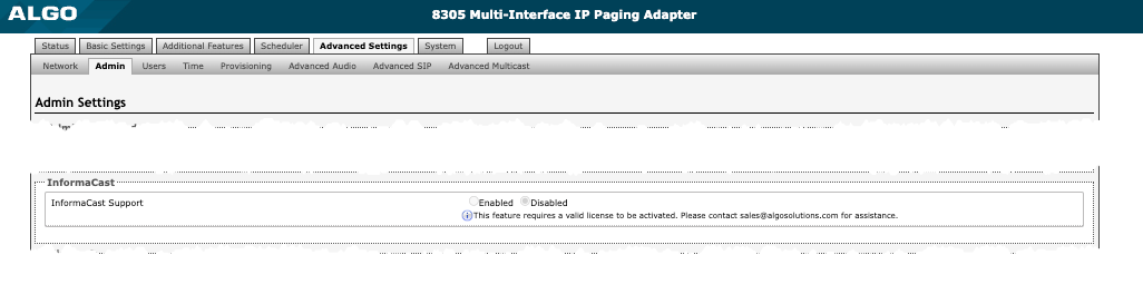
InformaCast
| |
InformaCast Support | This feature requires a valid InformaCast license to be activated. Please contact sales@algosolutions.com for assistance. |
Syn-Apps
As a Syn-Apps Partner, Algo products have been Syn-Apps Certified for compatibility and interoperability.
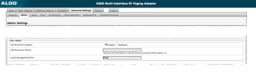
Syn-Apps The SA-Announce feature cannot be used when Multicast Transmitter mode or Poly mode is enabled. To enable SA-Announce mode, set Multicast Mode to None in Basic Settings → Multicast.
| |
SA-Announce Support | Enable to convert unicast streams to multicast and deliver them to the target endpoints. |
SA-Announce Server | Enter the SA-Announce Server to use the Syn-Apps paging feature. Leave the field blank to use the server provided by the DHCP Option 72. |
Local Management Port | Enter the local management port for the SA-Announce Server. |
Microsoft Teams
Algo devices are certified by and compatible with Microsoft Teams. When registered in the Microsoft Teams SIP Gateway, the 8305 can be configured to accommodate dozens of applications or deliver Teams-based communication throughout facilities.
Microsoft
| |
Microsoft Teams Support | Enable to provision the device via Microsoft’s servers. The device reboot will take up to 5 minutes to complete. This feature requires a compatible release from Microsoft. |

DeviCe Management
ADMP
The Algo Device Management Platform (ADMP) is a cloud-based device management solution to manage, monitor, and configure Algo IP endpoints from any location. Devices can be easily grouped via a tagging functionality, allowing devices to be coded by district, department, or function to easily oversee many devices. Devices can be supervised for connectivity and email-based notifications can be sent should devices go offline, allowing for a real-time overview of device status.
To connect your 8305 to your ADMP account, use the web interface and navigate to Advanced Settings → Admin → ADMP Cloud Monitoring.
Note that if you choose to use ADMP to manage your devices, the Algo 8300 IP Controller cannot be used at the same time.
To learn more about ADMP and how to purchase a license, visit the website.
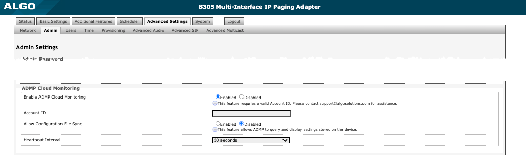
ADMP Cloud Monitoring
| |
Enable ADMP Cloud Monitoring | The Algo Device Management Platform (ADMP) simplifies the process of managing, monitoring, and maintaining Algo devices from any location. This feature requires a valid Account ID. To learn more about ADMP and how to purchase a license, visit the website. |
Algo 8300 IP Controller
The Algo 8300 IP Controller is designed for centralized Algo endpoint monitoring and supervision. Any Algo SIP endpoint device, including the 8305, can be monitored on the network via the 8300 dashboard.
Note that if you choose to use the Algo 8300 IP Controller to manage your devices, ADMP cannot be used at the same time.
Learn more about the Algo 8300 IP Controller.
SNMP
Simple Network Management Protocol (SNMP) can be used to monitor and manage the 8305.
To configure your SNMP settings, use the web interface and navigate to Advanced Settings → Admin → Simple Network Management Protocol.
Simple Network Management Protocol
| |
SNMP Support | The existing setting will respond to a simple status query for automated supervision. |
SNMP Community String | Speak to your IT Administrator for more information. |
SNMPv3 Security | Speak to your IT Administrator for more information. |

RTCP
Real-Time Transport Control Protocol (RTCP) can be used to monitor data delivery on the 8305.
To configure your RTCP settings, use the web interface and navigate to Advanced Settings → Admin → RTP Control Protocol (RTCP).
RTP Control Protocol (RTCP)
| |
RTCP Port Selection | Select how a port will be chosen to send or receive RTCP packets. Note: If Next Higher Port is selected, ensure that the default multicast zone definitions are modified so that zones are only assigned to even-numbered ports, leaving the next higher odd-numbered ports free for RTCP packets. |

System Configuration
Network Settings
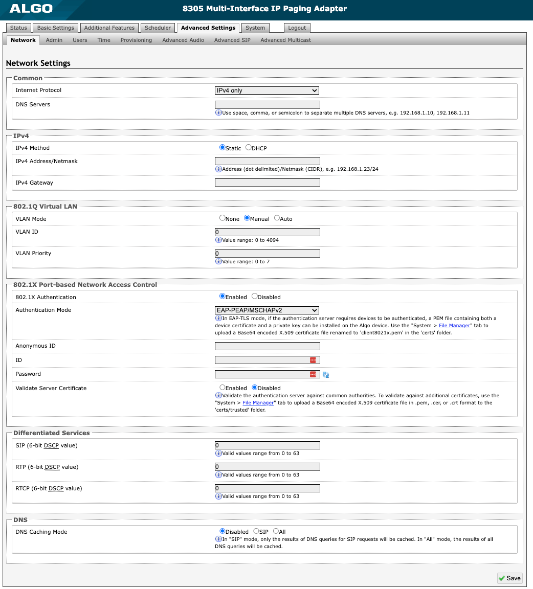
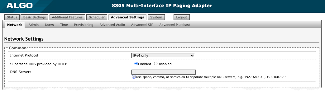
Figure 22: Network settings
Common
| |
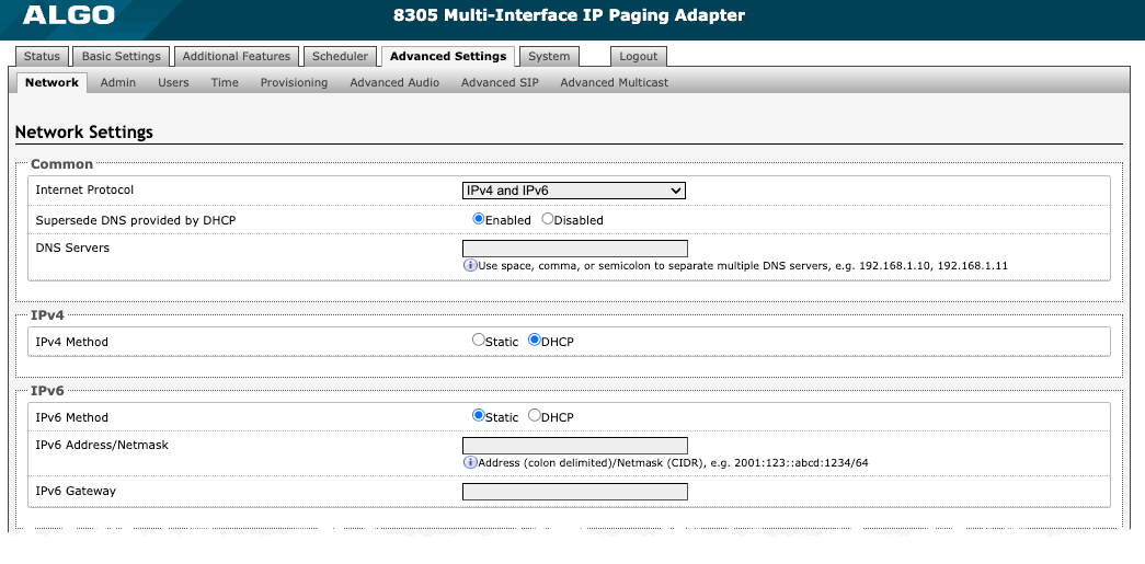
Internet Protocol | Use the dropdown to select IPv4 Only or IPv4 and IPv6. If IPv6 is also configured, it will have to be set up via DHCP or statically, similarly to the IPv4. |
Supersede DNS provided by DHCP | Use this option to enter a custom DNS server address and supersede the one sent via DHCP. |
DNS Servers | Add one or multiple DNS servers when Supersede DNS provided by DHCP is enabled. Separate each server by a space, comma, or semicolon. |
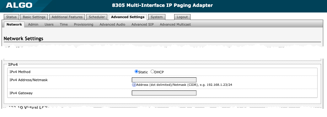
IPv4
| |
IPv4 Method | The 8305 can be set to a static or DHCP IP address. DHCP is an IP standard designed to simplify the administration of IP addresses. When selected, DHCP will automatically configure IP addresses for each 8305 on the network. DHCP is selected by default. When Static is selected, the IP address entered in the fields below will be used by the device. |
IPv4 Address/Netmask | Enter the static IP address and netmask (CIDR format) for the 8305 (e.g., 192.168.1.23/24). |
IPv4 Gateway | Enter the gateway address. |
IPv6
| |
IPv6 Method | The 8305 can be set to a static or DHCP IP address. DHCP is an IP standard designed to simplify the administration of IP addresses. When selected, DHCP will automatically configure IP addresses for each 8305 on the network. When DHCP is selected, the DHCP will automatically configure IP addresses for the 8305 on the network. |
IPv6 Address/Netmask | Enter the static IP address and netmask (CIDR format) for the 8305 (e.g., 2001:123::abcd:1234/64). |
IPv46Gateway | Enter the gateway address. |
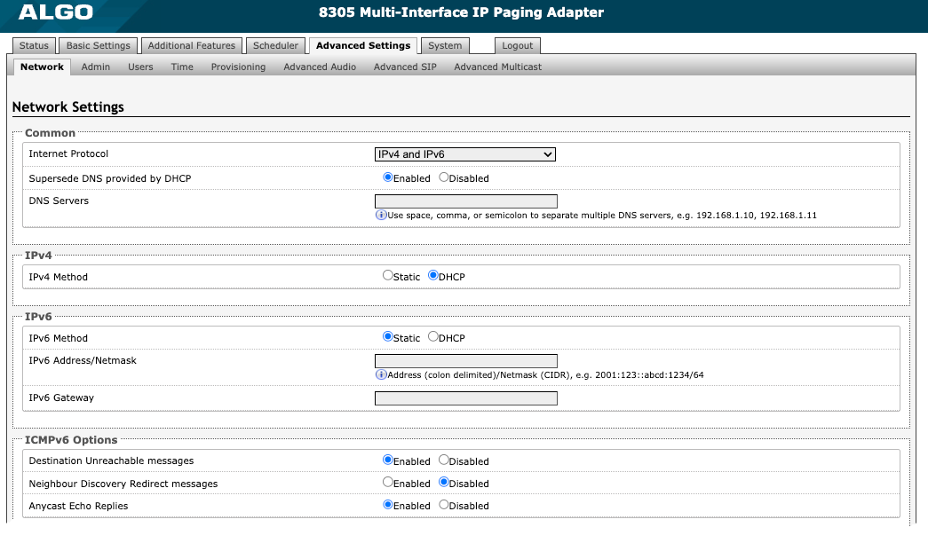
ICMPv6 Options | |
Destination Unreachable messages | Enable to restrict traffic by filtering ICMPv6 packets. |
Neighbour Discovery Redirect messages | Enable to restrict traffic by filtering ICMPv6 packets. |
Anycast Echo Replies | Enable to restrict traffic by filtering ICMPv6 packets. |
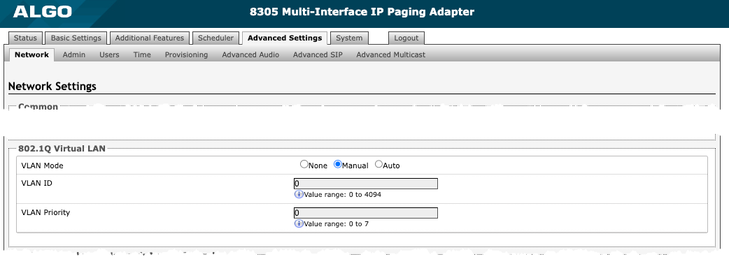
802.1Q Virtual LAN
| |
VLAN Mode | VLAN tagging is the networking standard that supports Virtual LANs (VLANs) on an Ethernet network. The standard defines a system of VLAN tagging for Ethernet frames and the accompanying procedures to be used by bridges and switches in handling such frames. The standard also provides provisions for a quality-of-service prioritization scheme known as IEEE 802.1p and defines the Generic Attribute Registration Protocol. |
VLAN ID | Specify the VLAN that the Ethernet frame belongs to. The hexadecimal values 0x000 and 0xFFF are reserved. All other values may be used as VLAN identifiers, allowing up to 4094 VLANs. The reserved value 0x000 indicates that the frame does not belong to any VLAN. In this case, the 802.1Q tag specifies only a priority and is referred to as a priority tag. |
VLAN Priority | Set the frame priority level. Otherwise known as Priority Code Point (PCP), VLAN Priority is a 3-bit field that refers to the IEEE 802.1p priority or frame priority level. Values are from 0 (lowest) to 7 (highest). |
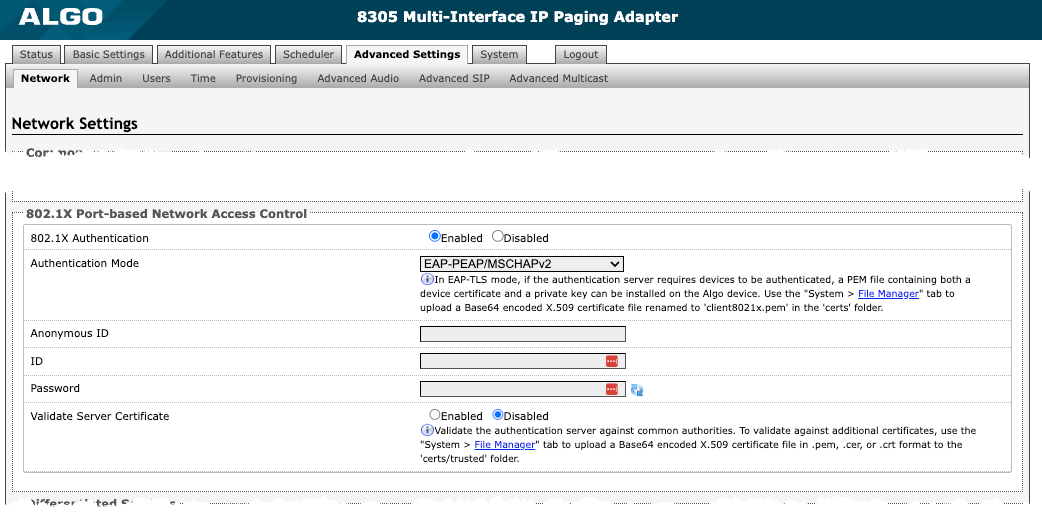
802.1X Port-based Network Access Control
| |
802.1x Authentication | Enable to add credentials to access LAN or WLAN that have 802.1X network access control (NAC). You can ask your IT Administrator for this information |
Authentication Mode | Select the desired authentication mode. |
Anonymous ID | If configured, the 8305 will send the anonymous ID to the authenticator instead of the 802.1X client username. |
ID | The ID should contain a string identifying the IEEE 802.1X authenticator originating the request. Ask your IT administrator for details. |
Password | Ask your IT administrator for details. |
Validate Server Certificate | Enable to validate the authentication server against common authorities. To validate additional certificates, go to the System → File Manager to upload a Base64 encoded X.509 certificate file in .pem, .cer, or .crt format to the ‘certs’ folder. |
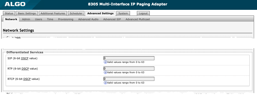
Differentiated Services Differentiated Services provide quality of service if the DSCP protocol is supported on your network. Differentiated Services can be specified independently for SIP control packets and RTP and RTCP audio packets.
| |
SIP (6-bit DSCP value) | Enter the DSCP value for SIP packets. |
RTP (6-bit DSCP value) | Enter the DSCP value for RTP packets. |
RTCP (6-bit DSCP value) | Enter the DSCP value for RTCP packets. |
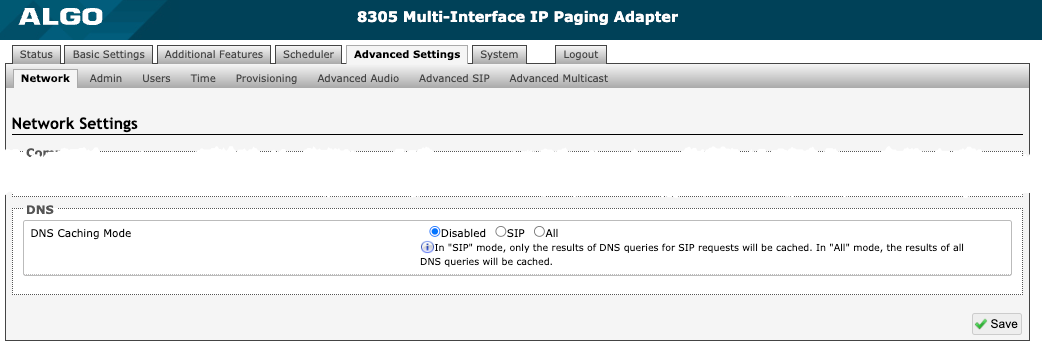
DNS
| |
DNS Caching Mode | There are three mode options:
|
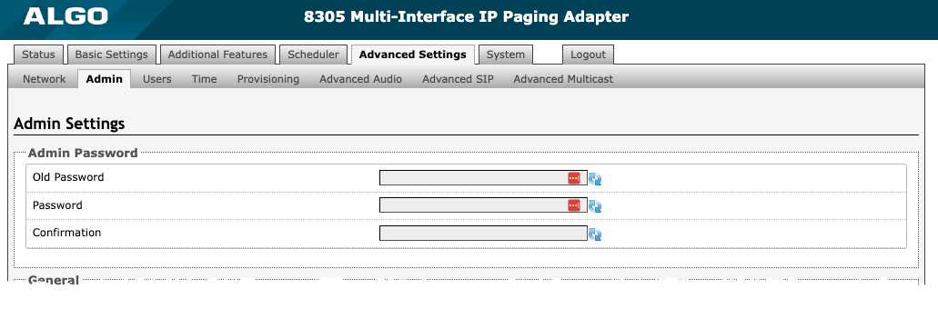
Admin
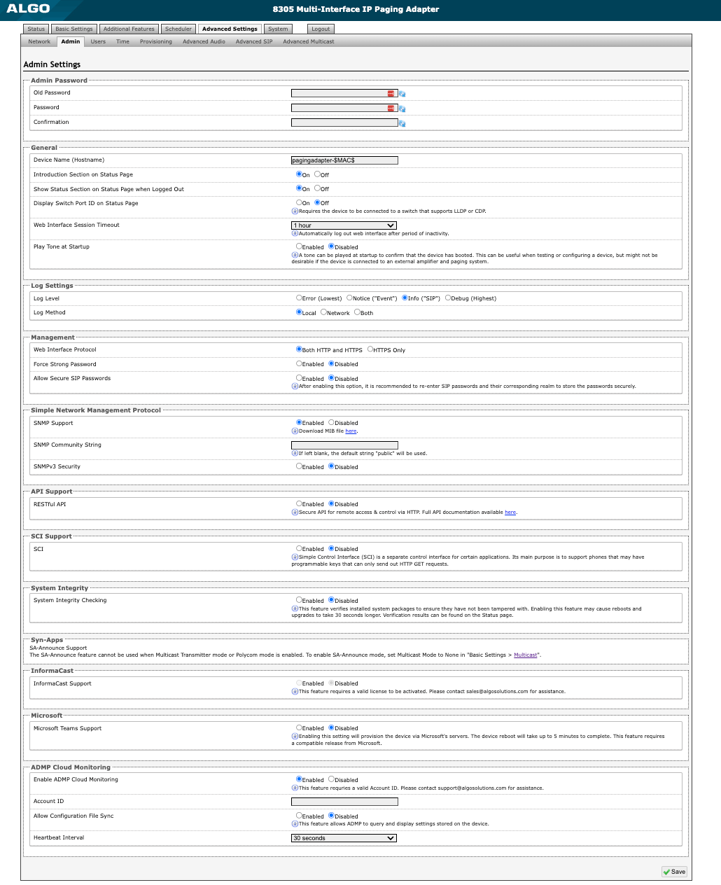
Figure 23: Admin settings.
Admin Password Use this section to change the admin password for logging into your 8305 web interface. It’s recommended that you change the admin password from the default to secure the device on your network.
| ||
Old Password | Enter the old admin password. The default password when you first get the device is algo. | |
Password | Enter a new admin password to log into the 8305 web interface. Make sure the new password is stored safely. If the password is forgotten, you must reset the device entirely with the Reset Button to restore the default password. All other settings will be reset to the original default settings as well. For additional password security, see the setting: Force Strong Password. | |
Confirmation | Re-enter your new admin password. | |
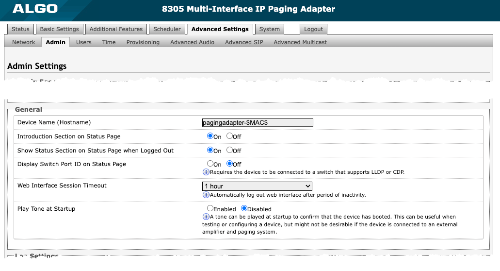
General
| ||
Device Name (Hostname) | Add a name to identify the device in the Algo Network Device Locator Tool. | |
Introduction Section on Status Page | Turn On to show the introduction text on the login screen. | |
Show Status Section on Status Page when Logged Out | Turn On to allow others to view the status page without logging in. If turned Off, the settings and configurations on the status page will be hidden entirely unless a user is logged in to ensure only trusted users can view device information. | |
Display Switch Port ID on Status Page | Turn On to display the Switch Port ID on the Status Page. This option is only possible if the 8305 is connected to a switch that supports LLDP or CDP. | |
Web Interface Session Timeout | Set the maximum duration of inactivity to log a user out of the web interface automatically. | |
Play Tone at Startup | Enable to play a tone at start-up to confirm that the device has booted. This can be useful when testing or configuring a device but might not be desirable if the device is connected to an external legacy communication system and paging system. | |
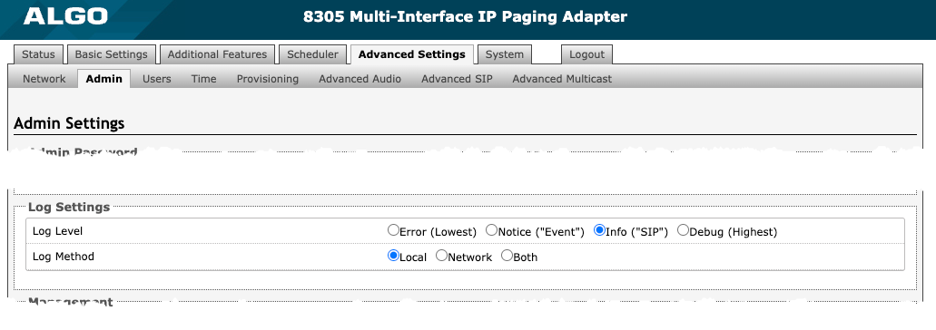
Log Settings
| |
Log Level | This setting should only be used after consulting with the Algo support team. |
Log Method | Select a Log Method:
|
Log Server | Enter the Syslog server address provided by your IT administrator. |
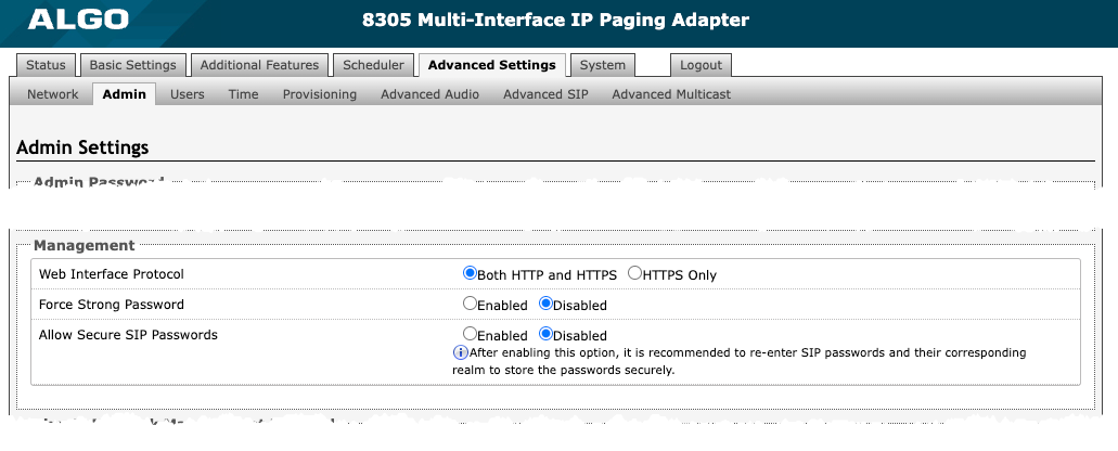
Management
| |
Web Interface Protocol | HTTPS is always enabled on the device. HTTP is enabled by default but may be disabled. To do so, select HTTPS Only mode so requests are automatically redirected to HTTPS. Note that no security certificate exists since the device can have any address on the local network. Therefore, most browsers will provide a warning when using HTTPS. |
Force Strong Password | When Enabled, you can enforce a secure password for the 8305 web interface for additional protection. The password requirements for a strong password are:
|
Allow Secure SIP Password | When Enabled, SIP passwords are stored in the configuration file in an encrypted format to prevent viewing and recovery. If enabled, navigate to Basic Settings → SIP and fill out the field Realm. To obtain your SIP Realm information, contact your SIP Server administrator or check the SIP log file for a registration attempt. The Realms may be the same or different for all the extensions used. All the configured Authentication Password(s) must be re-entered here as well as any other locations where SIP extensions have been configured to save the encrypted password(s). If the Realm is changed later, all passwords must be re-entered to save the passwords with the new encryption. |
Display Switch Port ID on Status Page | Turn On to display the Switch Port ID on the Status Page. This option is only possible if the 8305 is connected to a switch that supports LLDP or CDP. |
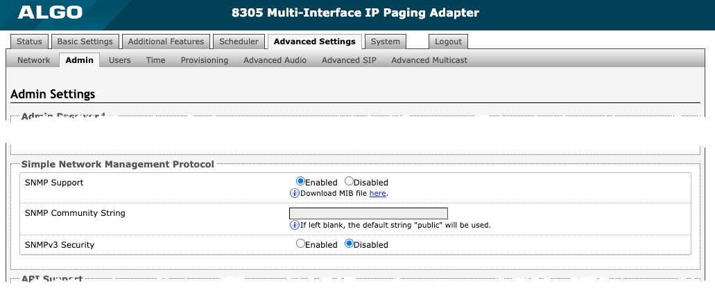
Simple Network Management Protocol
| |
SNMP Support | The existing setting will respond to a simple status query for automated supervision. |
SNMP Community String | Speak to your IT Administrator for more information. |
SNMPv3 Security | Speak to your IT Administrator for more information. |
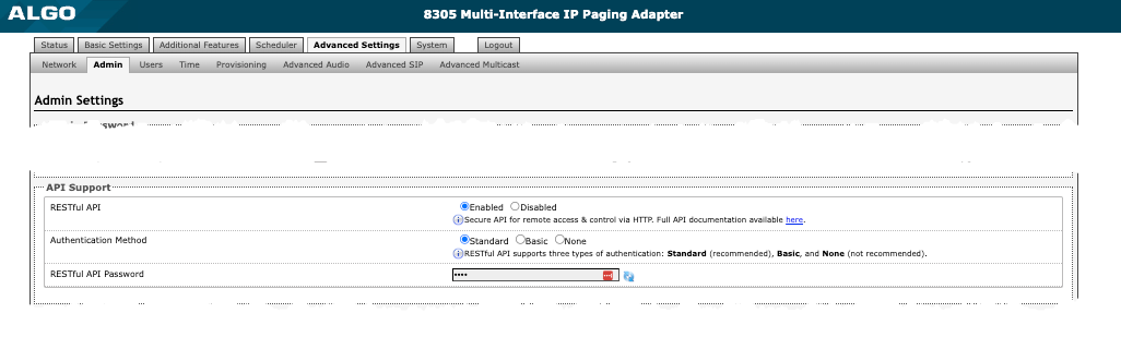
API Support
| |
RESTful API | Enable a secure API for remote access and device control via HTTP. For more information, see the Algo RESTful API Guide. |
Authentication Method | Speak to your IT Administrator for more information. |
RESTful API Password | Speak to your IT Administrator for more information. |
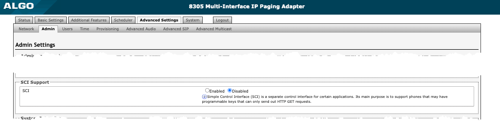
SCI Support
| |
SCI | Simple Control Interface (SCI) is a separate control interface for certain applications. Its primary purpose is to support phones that may have programmable keys that can only send out HTTP GET requests. |
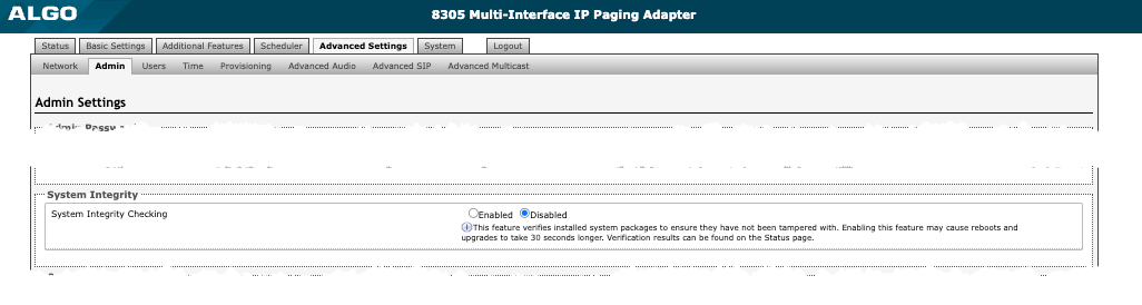
System Integrity
| |
System Integrity Checking | Enable this feature to verify that installed system packages have not been tampered with by running a check. Enabling this feature may cause reboots and upgrades to take 30 seconds longer. Verification results can be found on the Status tab. |
Syn-Apps The SA-Announce feature cannot be used when Multicast Transmitter mode or Poly mode is enabled. To enable SA-Announce mode, set Multicast Mode to None in Basic Settings → Multicast.
| |
SA-Announce Support | Enable to convert unicast streams to multicast and deliver them to the target endpoints. |
SA-Announce Server | Enter the SA-Announce Server to use the Syn-Apps paging feature. Leave the field blank to use the server provided by the DHCP Option 72. |
Local Management Port | Enter the local management port for the SA-Announce Server. |

InformaCast
| |
InformaCast Support | This feature requires a valid InformaCast license to be activated. Please contact sales@algosolutions.com for assistance. |

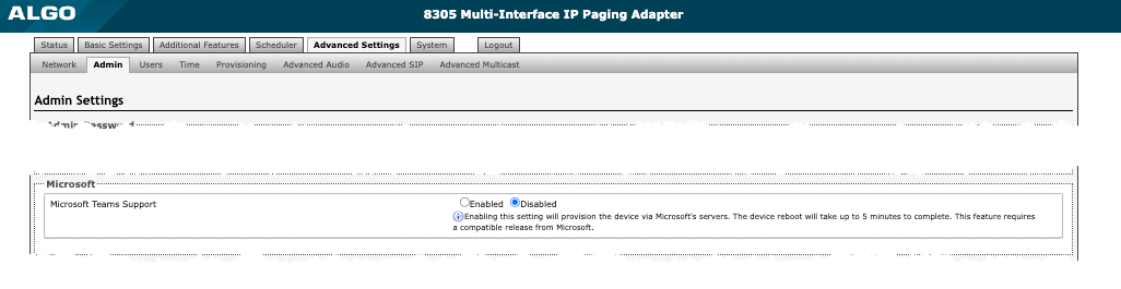
Microsoft
| |
Microsoft Teams Support | Enable to provision the device via Microsoft’s servers. The device reboot will take up to 5 minutes to complete. This feature requires a compatible release from Microsoft. |
ADMP Cloud Monitoring
| |
Enable ADMP Cloud Monitoring | The Algo Device Management Platform (ADMP) simplifies the process of managing, monitoring, and maintaining Algo devices from any location. This feature requires a valid Account ID. To learn more about ADMP and how to purchase a license, visit the website. |

Users
Use these settings to create a separate user who only has access to the scheduler on the 8305. This may be useful, for example, in a school where you may want someone to have access to bell schedule modification, but don’t want them to have access to all 8305 configuration settings.
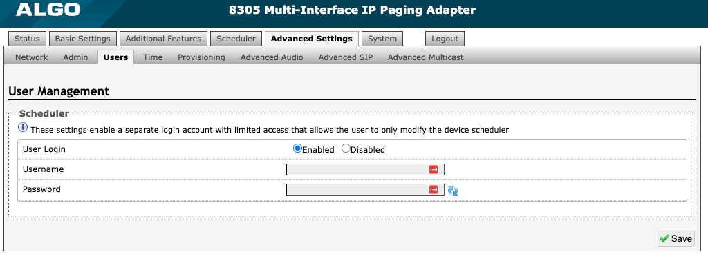
Figure 24: Users settings
Time
Time and date are used for logging purposes and the scheduler feature.
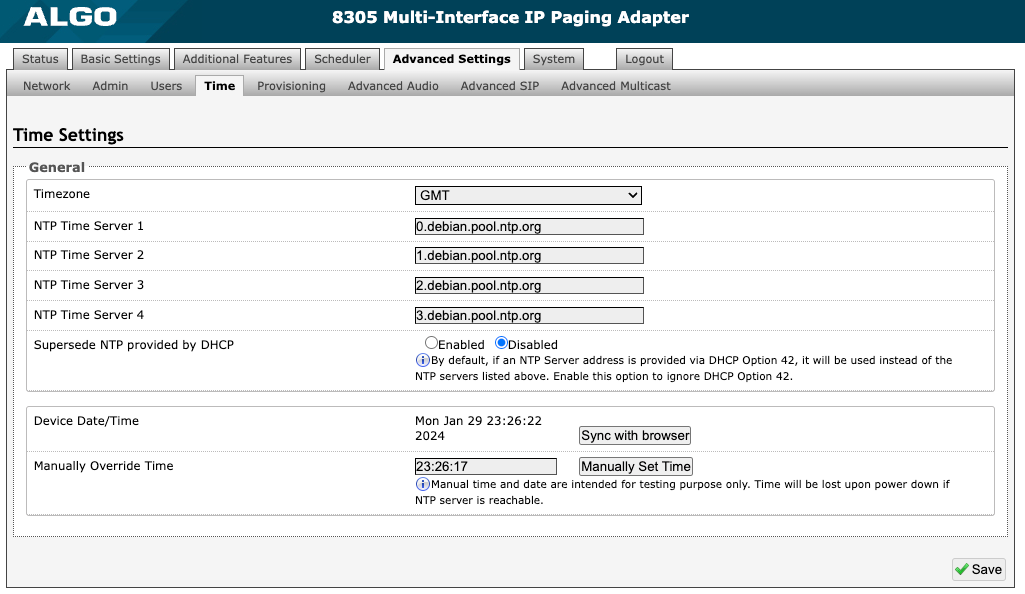
Figure 25: Time settings
General | |
Timezone | Select a time zone for 8305 settings. |
NTP Time Servers 1/2/3/4 | The device will attempt to use Timer Server 1 and work down the list if one or more of the time servers become unresponsive. These settings are pre-populated with public NTP servers hosted on the internet. To use these, the device requires internet connection. Alternatively, this can be customized to point the device to any other NTP server hosted or premise-based. |
Supersede NTP provided by DHCP | By default, if an NTP Server address is provided via DHCP Option 42, it will be used instead of the NTP servers listed above. Enable this option to ignore DHCP Option 42. |
Device Date/Time | This field shows the current time and date set on the device. If you are testing the device on a lab network that does not have access to an external NTP server, click Sync with browser to temporarily set the time on the device. This time value will be lost at power down or overwritten if connection to the NTP server is available. Time and date are used for logging purposes and the scheduler feature. |
Manually Override Time | Manual time and date are intended for testing purposes only. Time will be lost upon power down if the NTP server is reachable. |
Provisioning
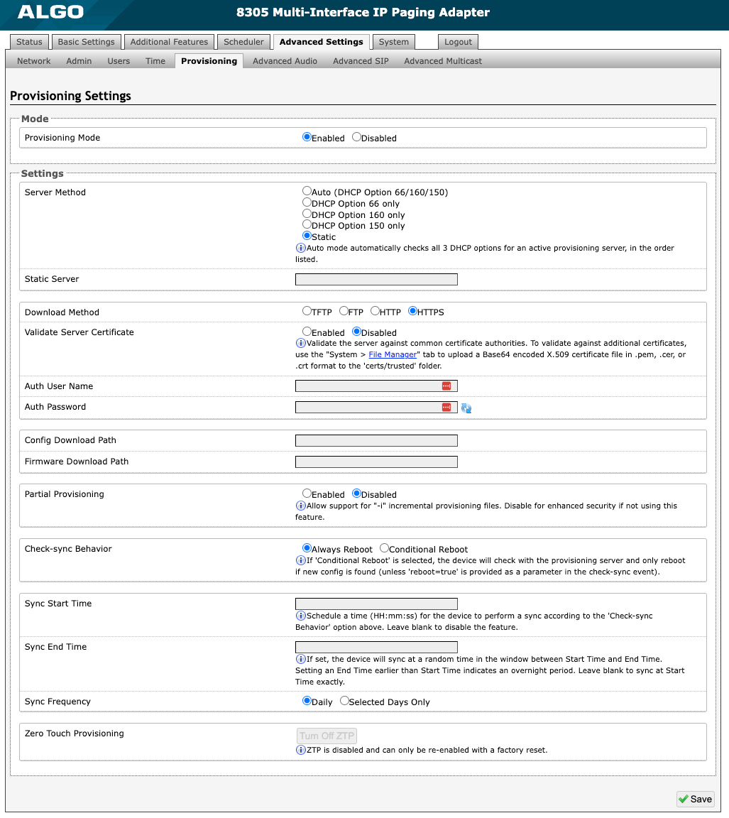
Figure 26: Provisioning settings
Mode
| |
Provisioning Mode | Enabling provisioning allows installers to pre-configure 8305 on a network before installation. This is typically done for large deployments to save time and ensure consistent setups. It is recommended that Provisioning Mode be set to Disabled if this feature is not in use. This will prevent unauthorized re-configuration of the device if DHCP is used. |
Settings
| |
Server Method | Select a Server Method.
For provisioning to work with a DHCP option, DHCP must be enabled under Advanced Settings → Network → IPv4. |
Static Server | Enter the server address or domain. |
Download Method | Select your preferred method for downloading provisioning files. The options are:
The 8305 configuration files can be automatically downloaded from a provisioning server using DHCP Option 66. This option code (when set) supplies a TFTP boot server address to the DHCP client to boot from. One of two files can be uploaded on the Provisioning Server (for access via TFTP, FTP, HTTP, or HTTPS):
Both protocol and path are supported for Option 66, allowing for http://myserver.com/config-path to be used. |
Validate Server Certificate | Enable to verify the server. This checks if the certificate provided by the server is signed by any CAs included in the list of trusted CAs (used by the Debian infrastructure and Mozilla browsers). If a certificate signed by any of these CAs is received, that server will be trusted. This parameter can also be enabled through provisioning: Prov.download.cert = 1 |
(FTP) Auth User Name | Speak to your IT Administrator for more information. |
(FTP) Auth Password | Speak to your IT Administrator for more information. |
(HTTP) Auth User Name | Speak to your IT Administrator for more information. |
(HTTP) Auth Password | Speak to your IT Administrator for more information. |
(HTTPS) Validate Server Certificate | Speak to your IT Administrator for more information. |
(HTTPS) Auth User Name | Speak to your IT Administrator for more information. |
(HTTP) Auth Password | Speak to your IT Administrator for more information. |
Config Download Path | Enter the path where the configuration file is located within the provisioning server (e.g., algo/config/8305 ). |
Firmware Download Path | Enter the path where the firmware file is located within the provisioning server (e.g., algo/firmware/8305 ). |
Partial Provisioning | Enable to allow support for “-i” incremental provisioning files. Disable for enhanced security if this is not required. |
Check-sync Behavior | Select Always Reboot to set the 8305 to always reboot despite other settings. Select Conditional Reboot to set the 8305 to check the provisioning server. Only reboot if a new config is found (unless “reboot=true” is provided as a parameter in the check-sync event). |
Sync Start Time | Set a time (HH:mm:ss) for the device to perform a sync according to the Check-sync Behavior setting. Leave this blank if not needed. |
Sync End Time | If set, the device will sync randomly in the window between Sync Start Time and Sync End Time. Setting an End Time earlier than the Start Time indicates an overnight period. Leave blank to lank to sync exactly at the set start time. |
Sync Frequency | Select the sync frequency. Frequency can be set to Daily or Selected Days Only. |
Sync Days | Select the days of the week to for syncs to occur. |
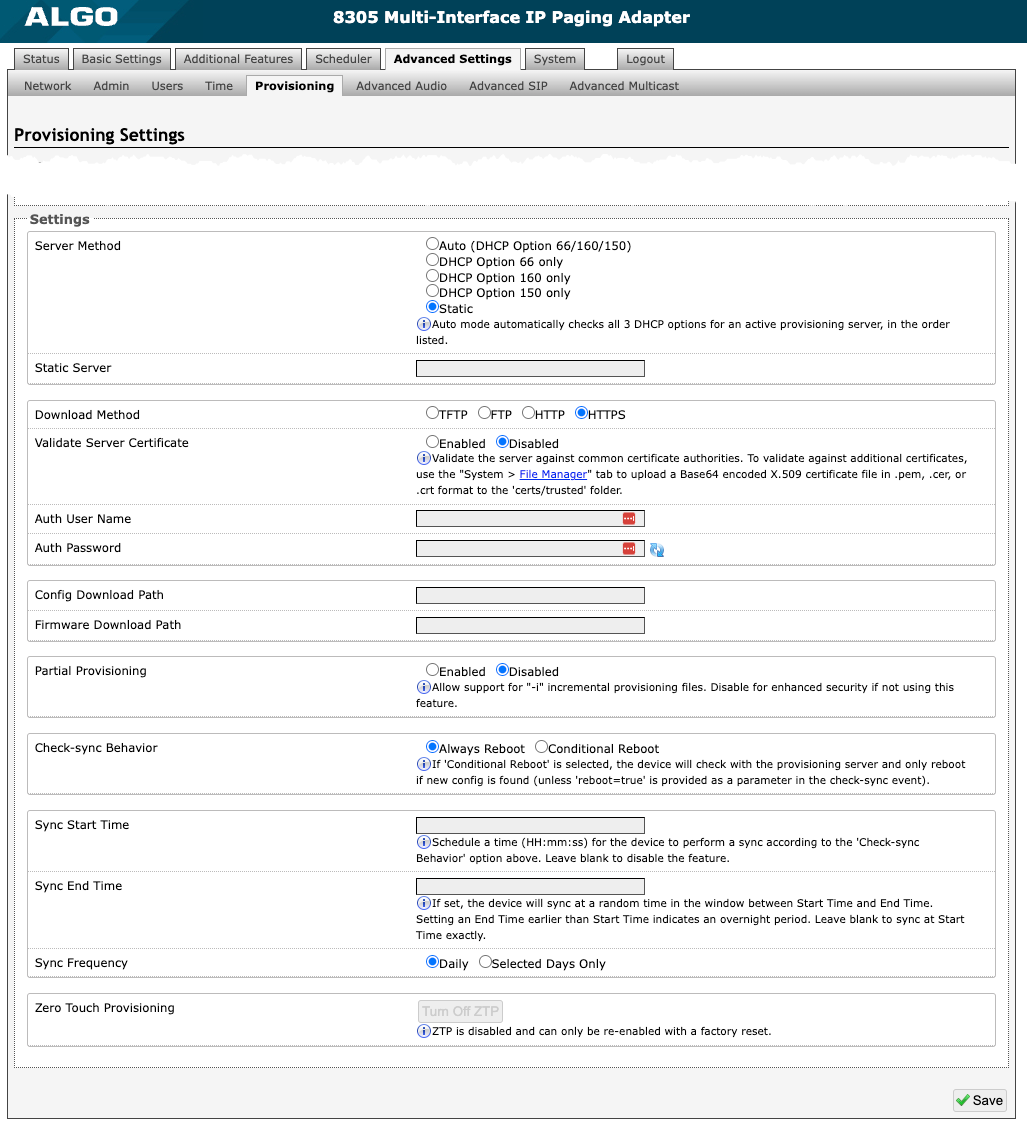
MD5 Checksum
If using TFTP as a download mode, a .md5 checksum file must be uploaded to the provisioning server In addition to the .conf file. This checksum file is used to verify that the .conf file is transferred correctly without error.
To generate a .md5 file, you can use tools such as http://www.fourmilab.ch/md5. To use this tool, simply download and unzip the .md5 program in a command prompt. The correct .md5 file will be generated in the same directory. To generate lowercase letters, use the “-l” parameter.
Generating a generic configuration file
This configuration file is device-generic in terms of MAC address and will be used by all connected 8305 devices.
If using a generic configuration file, extensions, and credentials must be entered manually once the 8305 has automatically downloaded the configuration file.
To see Algo’s SIP endpoint provisioning guide, visit www.algosolutions.com/provision
Generating a specific configuration file
The specific configuration file will only be downloaded by the 8305 with the MAC address specified in the configuration file name.
Since all necessary settings can be included in this file, the 8305 will be ready to work immediately after downloading the configuration file. The MAC address of each 8305 can be found on the back label of the unit.
To see Algo’s SIP endpoint provisioning guide, visit www.algosolutions.com/provision
Maintenance
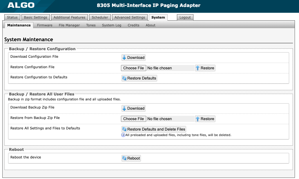
Figure 27: Maintenance settings.
Backup/Restore Configuration
| |
Download Configuration File | Save 8305 configuration settings to a text file for backup or to set up a provisioning configuration file. |
Restore Configuration File | Restore settings by uploading a backup file. |
Restore Configuration to Defaults | Reset all 8305 Multi-Interface IP Paging Adapter settings to factory default values. |
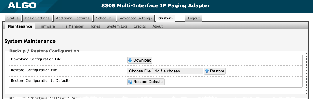
Backup/Restore All User Files
| |
Download Backup Zip File | Download the 8305 configuration settings and uploaded files in File Manager (ex., certificates, licenses, and tones) to a backup ZIP file. |
Restore from Backup Zip File | Restore the 8305 configuration settings and files in File Manager (ex., certificates, licenses, and tones) by uploading a backup zip file. |
Restore All Settings and Files to Defaults | Reset the 8305 configuration settings. All preloaded and uploaded files, including tone files, will be deleted |
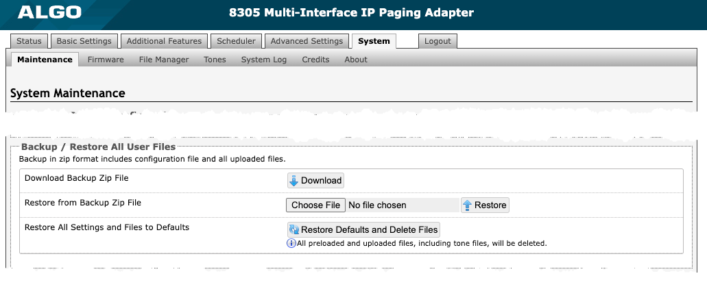
Reboot
| |
Reboot the Device | Reboots the device. |
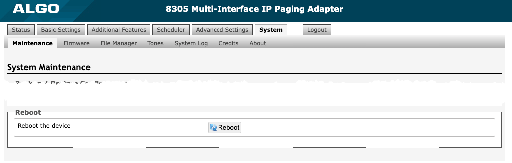
Firmware
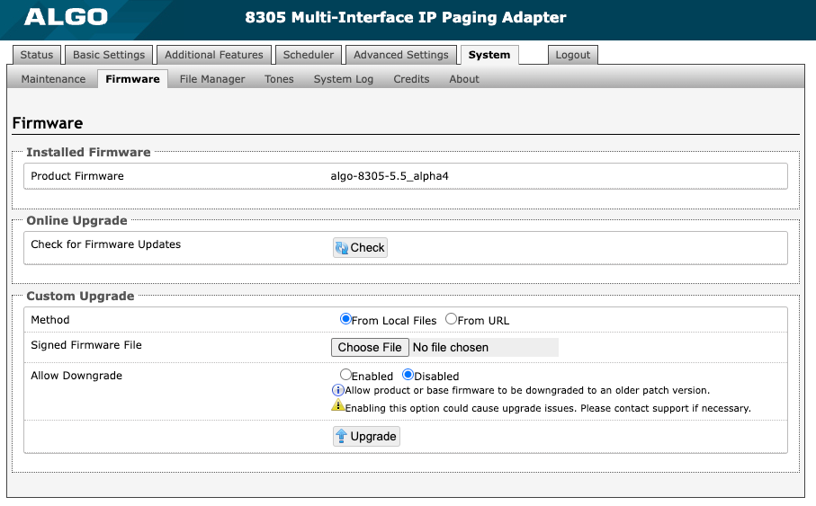
Figure 28: Firmware settings.
Installed Firmware
| |
Product Firmware | Displays the current firmware on the device. |
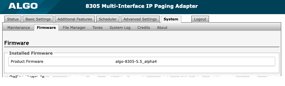
Online Upgrade
| ||
Check for Firmware Updates | Click Check to check for the latest firmware. If the firmware is up to date, Latest Firmware will state Firmware up to date. If your firmware is outdated, the new firmware availability will be listed. Internet connection is required. | |
Custom Upgrade
| ||
Method | Select a method for firmware upgrades to occur. This can be done From Local Files or From URL. | |
Signed Firmware File | Use to upgrade firmware from a local file. To do this, download the firmware file from https://www.algosolutions.com/firmware-downloads/ then upload the file by clicking on Choose File and selecting the firmware file. Click Upgrade at the bottom of the interface. Once the upgrade is complete, you can confirm the firmware version is changed by looking at the top right of the web interface. | |
Upgrade URL | Instead of downloading the firmware file https://www.algosolutions.com/firmware-downloads/, you may add the download link here instead. Click Upgrade at the bottom of the interface. Once the upgrade is complete, you can confirm the firmware version is changed by looking at the top right of the web interface. | |
Allow Downgrade | Enable to allow product or base firmware to be downgraded to an older patch version. Enabling this option could cause future upgrade issues. If you require downgrading, please contact support@algosolutions.com for assistance. | |
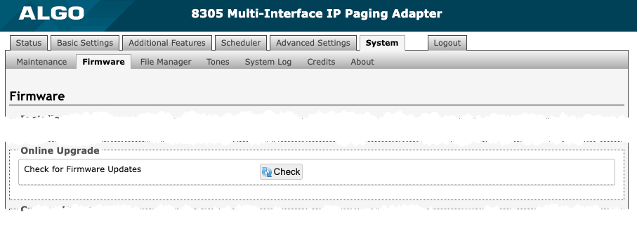
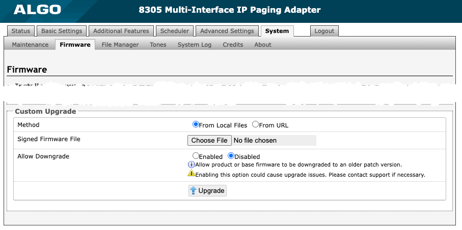
File Manager
The 8305 has 1GB of storage space for additional files.
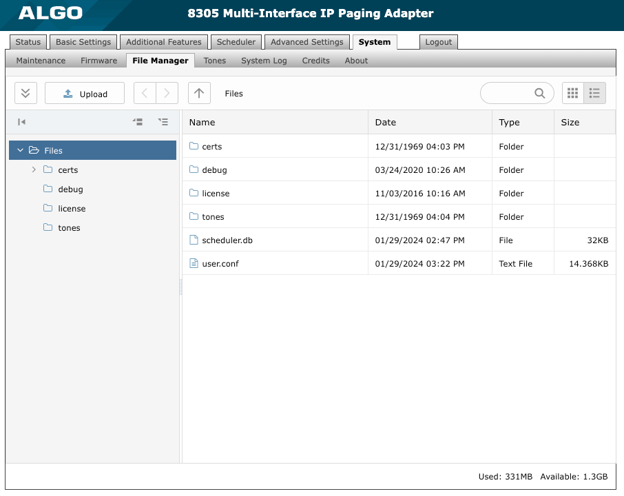
Figure 29: File manager settings.
Certs Folder
If you have enabled Validate Server Certificate under Advanced Settings → Advanced SIP or Advanced Settings → Provisioning and would like to validate against additional certificates, you can upload them here.
To install a public CA certificate on the Algo 8305:
Obtain a public certificate from your Certificate Authority (Base64 encoded X.509 .pem, .cer, or .crt).
Open the certs folder in the web interface by going to System → File Manager.
Upload the certificate files into the certs folder by clicking Upload in the top left corner of the file manager and select the certificate.
Reach out to support@algosolutions.com to get the complete list of pre-loaded trusted certificates.
Debug Folder
If you have any challenges with the device and work with the Algo support team to overcome or fix them, the debug folder will be used. The device will generate files containing information about the device and put them in the debug folder. You do not need to use this folder unless directed to by the Algo support team.
License Folder
If you would like to use Informacast on a device that hasn't been bundled with an Informacast license, you will need to purchase a license and put it into the license folder in the file manager.
Tones Folder
Custom audio files may be uploaded to play notifications. Audio files should be stored in the tones directory.
Existing files may be modified by downloading the original file, making the desired changes, then uploading the updated file with a different name. To download, right-click the tone and click Download.
Audio files must be in the following format:
WAV or MP3 format
Smaller than 200 MB
File names must be limited to 32 characters, with no spaces.
For further instructions, reference the Custom Tone Conversion and Upload Guide.
System Log
System log files are automatically created and can assist with troubleshooting if the 8305 does not behave as expected.
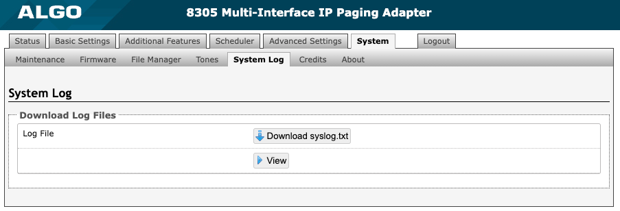
Figure 30: System log settings.
Logout
Log out of the web interface.
FCC Compliance Statement
This equipment has been tested and found to comply with the limits for a Class A digital device, pursuant to Part 15 of the FCC Rules. These limits are designed to provide reasonable protection against harmful interference when the equipment is operated in a commercial environment. This equipment generates, uses, and can radiate radio frequency energy. If it is not installed and used in accordance with the instruction manual, it may cause harmful interference to radio communications. Operations of this equipment in a residential area is likely to cause harmful interference, in which case the user will be required to correct the interference at their own expense.
Appendix: Algo Compatible Accessories
The relay input of the Algo 8305 Multi-Interface IP Paging Adapter can be activated by any normally open or normally closed switch, such as Algo input buttons or interfaces. The input switches can be connected to the back of the 8305 via the Terminal Block Relay Input. You can configure the Relay Input Mode on the web interface under the tabs Additional Features → Input/Output.
1202 Call Button
The 1202 Call Button is a one-touch button for event notification and response. It can be used with the 8305 for improved customer service, emergency notification, and non-emergency alerting. The Call Button’s one-touch button can trigger a single or continuous action, which can be halted via the small cancel/reset button located below the main call button.
Configuration
A pair of wires from the terminal block Relay Input on the back of the 8305 can connect to the center pair of the modular connector at the back of the Call Button. For more details, see the Algo 1202 Installation Sheet.
Figure 31: 1202 Call Button – the insert card is interchangeable. |
Figure 32: 1202 Call Button wiring. |


For more information on the 1202 Call Button, see the website.
1203 Call Switch
The 1203 Call Switch is a simple contact closure switch with an illuminated button and supervision capabilities. When used with the 8305, the 1203 can prompt a single action with one touch, or a continuous action if the button is held.
Configuration
A pair of wires can be run from the back of the device via a screw output connector to the 8305 via the Relay Input. For more details, check the Algo 1203 Getting Started Sheet.
Figure 33: 1203 Call Switch |
Figure 34: 1203 Call Switch wiring |


For more information on the 1203 Call Switch, see the website.
Mute Switch
The relay input on the 8305 is also compatible with any third-party switch or button that provides a contact closure (short-circuit) such as a mute switch.
Configuration
Apply an external switch (short-circuit) across the 8305 Relay Input terminals to enable a "disable" switch to control the device. This can be helpful in situations where you only want audio on or off, such as a boardroom to block paging during important meetings.
When using a mute switch, leave the Relay Input terminals open (no-connect) for regular full-volume operation.
After saving the Relay Input Mode to Mute Switch in the web interface, you’ll be able to settings for Multicast Override. Select one or many zones to override the mute switch settings in these zones.
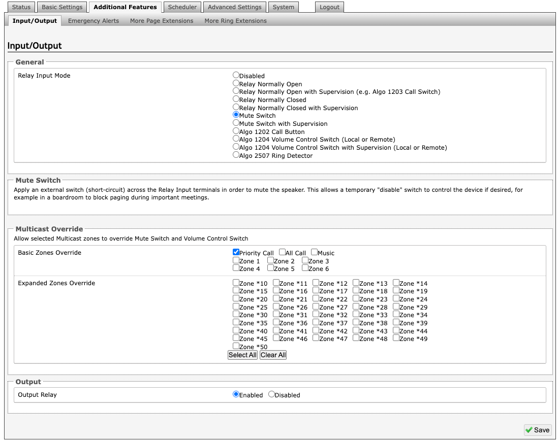
Figure 36. Configuring the 8305 when using a mute switch.
1204 Volume Control Switch
The 1204 Volume Control Switch allows a person to control the paging volume.
Configuration
To install the 1204, connect a single twisted pair wire to the Terminal Block Relay Input on the 8305.
Once connected, position 10 on the 1204 will match the maximum volume set in the web interface. Volumes set to lower levels will attenuate from the maximum volume.
The web interface and additional configurations for the 1204 are listed below.
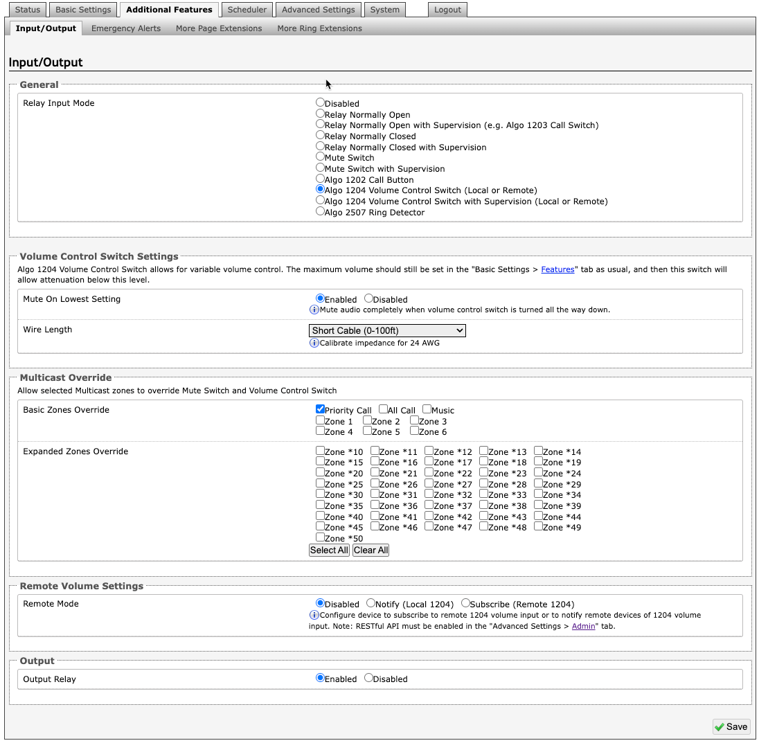
Figure 37. Configuring the 8305 when using a volume control switch.
Volume Control Switch Settings | |
Mute On Lowest Setting | Enable to mute audio when the volume control switch is turned to the lowest setting (1) |
Wire Length | Set to calibrate impedance for 24 AWG. |
Multicast Override | Multicast Override allows selected multicast zones to override the 1204 Volume Control settings for the selected zones. |
Remote Volume Settings | |
Remote Mode | Configure the device to subscribe to a remote 1204 volume input or to notify remote devices of 1204 volume input. Note that if Notify (Local 1204) or Subscribe (Remote 1204) are selected that a RESTful API must be enabled under Advanced Settings → Admin. |
Figure 38: 1204 Volume Control |
Figure 39: 1204 Volume Control Switch Wiring |

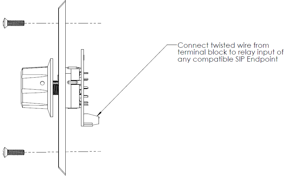
For more information on the 1204 Volume Control, see the website.
2507 Ring Detector
The 2507 Ring Detector can detect when a telephone is ringing and activate the 8305 to play a tone or pre-recorded announcement.
Configuration
Plug an analog telephone into the headset jack on one side of the 2507 Ring Detector and use the other side to connect the to the 8305 using the provided cable.
Once connected, you can use the 8305 web interface to set a Tone/Pre-Recorded Message for when an action is triggered under Additional Features → Input/Output.

Figure 40. The Algo 2507 Ring Detector