Disclaimer
The information contained in this document is believed to be accurate in all respects but is not warranted by Algo. The information is subject to change without notice and should not be construed in any way as a commitment by Algo or any of its affiliates or subsidiaries. Algo and its affiliates and subsidiaries assume no responsibility for any errors or omissions in this document. Revisions of this document or new editions of it may be issued to incorporate such changes. Algo assumes no liability for damages or claims resulting from any use of this manual or such products, software, firmware, and/or hardware.
No part of this document can be reproduced or transmitted in any form or by any means – electronic or mechanical – for any purpose without written permission from Algo.
For additional information or technical assistance in North America, please contact Algo’s support team:
1-604-454-3792
support@algosolutions.com
Important Safety Information
.png) Important Safety Information
Important Safety Information
This product is powered by a certified limited power source (LPS), Power over Ethernet (PoE); through CAT5 or CAT6 connection wiring to an IEEE 802.3at PoE+ or 802.3af compliant network PoE switch. The product is intended for installation indoors. All wiring connections to the product must be in the same building. If the product is installed beyond the building perimeter or used in an inter-building application, the wiring connections must be protected against overvoltage/transient. Algo recommends that this product is installed by a qualified electrician.
If you are unable to understand the English language safety information then please contact Algo by email for assistance before attempting an installation support@algosolutions.com.
Consignes de Sécurité Importantes
Ce produit est alimenté par une source d’alimentation limitée certifiée (alimentation par Ethernet); des câbles de catégorie 5 et 6 joignent un commutateur réseau à alimentation par Ethernet homologué IEEE 802.3at PoE+ or 802.3af. Le produit est conçu pour être installé à l’intérieur. Tout le câblage rattaché au produit doit se trouver dans le même édifice. Si le produit est installé au-delà du périmètre de l’édifice ou utilisé pour plusieurs édifices, le câblage doit être protégé des surtensions transitoires. Algo recommande qu’un électricien qualifié se charge de l’installation de ce produit.
Si vous ne pouvez comprendre les consignes de sécurité en anglais, veuillez communiquer avec Algo par courriel avant d’entreprendre l’installation au support@algosolutions.com.
Información de Seguridad Importante
Este producto funciona con una fuente de alimentación limitada (Limited Power Source, LPS) certificada, Alimentación a través de Ethernet (Power over Ethernet, PoE); mediante un cable de conexión CAT5 o CAT6 a un conmutador de red con PoE en cumplimiento con IEEE 802.3at PoE+ or 802.3af. El producto se debe instalar en lugares cerrados. Todas las conexiones cableadas al producto deben estar en el mismo edificio. Si el producto se instala fuera del perímetro del edificio o se utiliza en una aplicación en varios edificios, las conexiones cableadas se deben proteger contra sobretensión o corriente transitoria. Algo recomienda que la instalación de este producto la realice un electricista calificado.
Si usted no puede comprender la información de seguridad en inglés, comuníquese con Algo por correo electrónico para obtener asistencia antes de intentar instalarlo: support@algosolutions.com.
Wichtige Sicherheitsinformationen
Dieses Produkt wird durch eine zertifizierte Stromquelle mit begrenzter Leistung (LPS – Limited Power Source) betrieben. Die Stromversorgung erfolgt über Ethernet (PoE – Power over Ethernet). Dies geschieht durch eine Cat-5-Verbindung oder eine Cat-6-Verbindung zu einer IEEE 802.3at PoE+ or 802.3af-konformen Ethernet-Netzwerkweiche. Das Produkt wurde konzipiert für die Installation innerhalb eines Gebäudes. Alle Kabelverbindungen zum Produkt müssen im selben Gebäude bestehen. Wenn das Produkt jenseits des Gebäudes oder für mehrere Gebäude genutzt wird, müssen die Kabelverbindungen vor Überspannung und Spannungssprüngen geschützt werden. Algo empfiehlt das Produkt von einem qualifizierten Elektriker installieren zu lassenv.
Sollten Sie die englischen Sicherheitsinformationen nicht verstehen, kontaktieren Sie bitte Algo per Email bevor Sie mit der Installation beginnen, um Unterstützung zu erhalten. Algo kann unter der folgenden E-Mail-Adresse erreicht werden: support@algosolutions.com.
安全须知
本产品由认证的受限电源(LPS),以太网供电(PoE),通过 CAT5 或CAT6 线路联接至 IEEE 802.3at PoE+ or 802.3af 兼容的PoE 网络交换机供电。本产品适用于室内或建筑物周 边安装。所有联接本产品的线路必须源自同一建筑物。本产品如需用于超出建筑物周边范围或跨建筑物的安装,线路联接部分必须有过压和瞬态保护。Algo 建议本产品由专业电工安装。
如果您对理解英文版安全须知有问题,安装前请通过电子邮件和 Algo 联系,support@algosolutions.com 。
EMERGENCY COMMUNICATION
If used in an emergency communication application, the 8063 should be routinely tested. SNMP supervision is recommended for assurance of proper operation.
DRY INDOOR LOCATION ONLY
The 8063 IP Door Controller is intended for dry indoor locations only.
CAT5 or CAT6 connection wiring to an IEEE 802.3af compliant network PoE switch must not leave the building perimeter without adequate lightning protection.
No wiring connected to the 8063 IP Door Controller may leave the building perimeter without adequate lightning protection.
Overview
Introduction
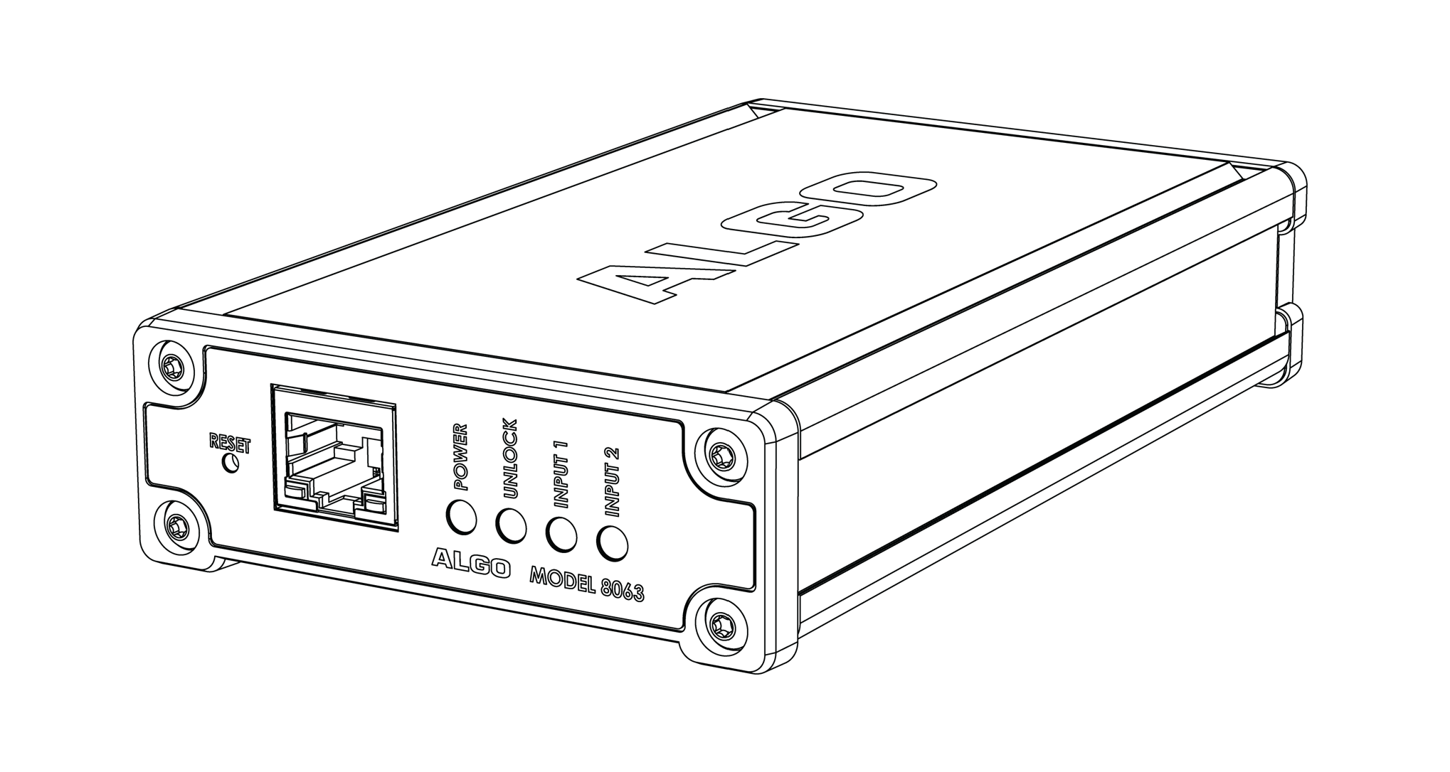
The 8063 IP Door Controller provides a dry contact relay closure for the activation of electronic door strikes. It is typically used in conjunction with an Algo Intercom, including the 8201, 8203, 8036, and 8039, allowing the door wiring to be kept securely inside the building to prevent unauthorized tampering. In this case, the 8063 does not require a SIP registration, and communicates only with the Algo Intercom via a secure communication path over the LAN.
In applications where voice communication is not required, the 8063 can also be used in standalone mode, and activated directly via a SIP call.
The 8063 also has two relay inputs, and one relay output, allowing it to interface with external sensors and switches, including magnetic door sensors for tracking the state of the door to prevent tailgating, or trigger an alarm if the door is held open.
What is Included
8063 IP Door Controller
Network Cable
Wall Mount Bracket
What is not Included
This User Guide
Door Strike
Door Strike Power Supply
Intercom (compatible with Algo 8201, 8203, 8036 & 8039)
Setup and Installation
Getting Started - Quick Install & Test
Note
This guide provides important safety information which should be read thoroughly before permanently installing the adapter.
Connect the wiring from your door strike (not included), to the Door Control relay output terminal block on the 8063 (either “Normally Open” [‘NO’] and “Common” [‘C’], or “Normally Closed” [‘NC’] and “Common” [‘C’], as appropriate for the door strike). See the Door Strike Wiring Guide for further information.
Connect the 8063 IP Door Controller to a PoE or PoE+ network switch. The blue lights on the front will remain on until boot up is completed – about one minute.
After the blue lights turn off, the IP address may be discovered by downloading the Algo locator tool to find Algo devices on your network: www.algosolutions.com/locator
Access the 8063 IP Door Controller web page by entering the IP address into a browser (Chrome, Firefox, Microsoft Edge, etc) and login using the default password algo.
Use the test buttons in the web interface (Basic Settings → Door Control & I/O) to confirm the operation of the door strike. Press the Unlock button to test that the door unlocks, and then press Lock again to confirm that it locks.
After confirming that the hardware installation with the door strike is successful, the 8063 can now be configured for use with either an Algo Intercom (typical application), or in Stand-Alone Mode (without an Algo Intercom and thus no voice path). Please choose the appropriate section below based on your application.
For Use with an Algo Intercom (Typical Application):
Open the web interface for the Algo Intercom (8201, 8203, 8036 or 8039) that is to communicate with the 8063, using the IP address for this device.
In the web interface for the Intercom, select the Network Door Controller options and enter the IP address of the 8063 here (and password), so that the Intercom can contact the 8063 in order to unlock the door. These settings are in Basic Settings → Door Control in the Intercom web interface – see the documentation of your specific Algo Intercom model (8201, 8203, 8036 or 8039) for further details.
Make a call to the Algo Intercom, and press ‘6’ (or appropriate DTMF code as configured on the Intercom) to unlock the door using the 8063 IP Door Controller.
For Stand-Alone Mode:
In the 8063 web inteface, enter the IP address or the name for the SIP server into the SIP Domain field under the Basic Settings → Stand-Alone Mode tab.
Enter the credentials (SIP Extension, Authentication ID, and Password) for the SIP extension.
Note
The Authentication ID may also be called Username for some SIP servers, and in some cases may be the same as the SIP extension.
Make a call to the controller by dialling the SIP extension of the adapter from a telephone.
Installation
The 8063 is wall mountable in a horizontal orientation using the supplied bracket.
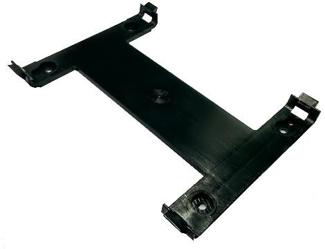 Example installation on ½” drywall:
Use appropriate drywall anchors for #8 screws, and pre-drill per anchor manufacturer’s instructions. Insert 4 anchors into the wall, and then attach bracket to wall anchors using #8 screws. Snap the 8063 into the bracket.
Connect the 8063 to a PoE network switch.
Programming and Configuration
The 8063 IP Door Controller is configurable using the web interface or provisioning features.
After boot up the blue lights on the front will turn off (except for the power light) and the adapter will have obtained an IP address. If there is no DHCP server the 8063 IP Door Controller will default to the static IP address 192.168.1.111.
The IP address may be discovered by downloading the Algo locator tool to find Algo devices on your network: www.algosolutions.com/locator
Enter the IP address (e.g. 192.168.1.111) into a browser such as Chrome, Firefox, or Microsoft Edge. The web interface should be visible and the default password will be algo in lower case letters.
Wiring Connections
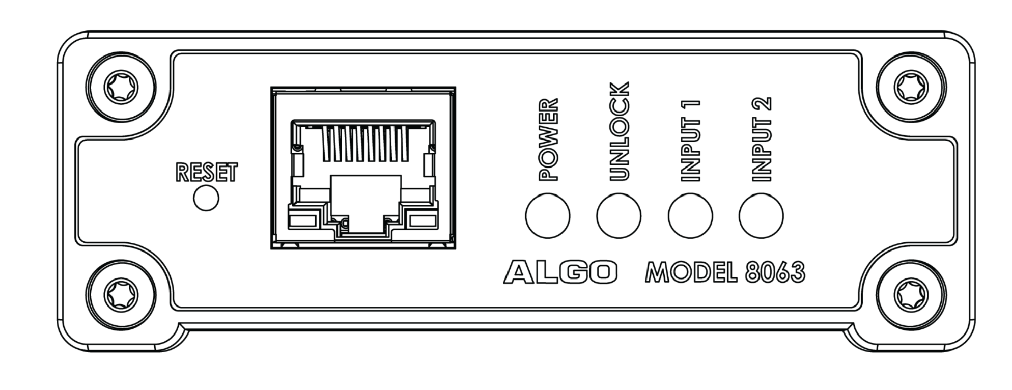
8063: Front View
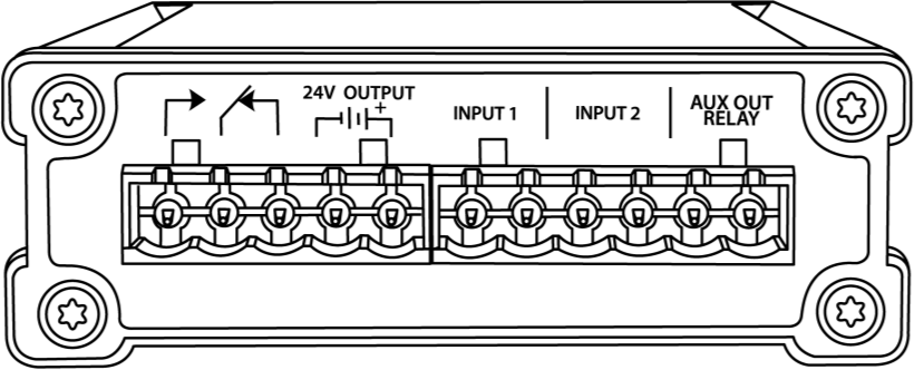
8063: Back View
Network Connection (Front)
The 8063 provides a RJ45 jack for network connection. A cable run from the switch can be terminated to a modular jack with connection by patch cord, or terminated with a RJ45 plug.
PoE can be used for most applications, whether provided by the network switch or injector. If using the 24V output to drive a high power door strike directly (as opposed to just using the relay in conjunction with the door strike’s existing power supply), then PoE+ may be used to allow more power. See the Specifications section for details on the current limits in each case.
There are two lights on the Ethernet jack:
Green light: On when Ethernet is working, flickers off to indicate activity on the port.
Amber light: Off when successful 100Mbps link is established. Typically on only briefly at power up.
Under normal conditions, the Amber light will turn on immediately after the Ethernet cable is first connected. This indicates that PoE power has been successfully applied. Once the device connects to the network, it will switch to the Green light instead, which will typically flicker indicating traffic on the network.
Reset
A recessed reset button (RST) next to the Ethernet Jack can only be used to reset the 8063 at time of power up. To return all settings to a factory default, wait until the SIP LED flashes and then press and hold the reset button until the POWER LED begins a double flash pattern. Release the reset button and allow the unit to complete its boot process.
Do not press the reset button until the POWER LED begins flashing.
A reset will set all configuration options to factory default including the password.
TLS for SIP Signalling and Provisioning
Algo devices that support firmware 1.6.4 or later support Transport Layer Security (TLS). This feature adds security by ensuring that Algo products can trust the hosted SIP server. This is useful for when third-party devices or attackers may try to intercept, replicate, or alter Algo products, and try to connect to the server. TLS protocol will ensure that third parties cannot read/modify any actual data. Previously security was less of a concern because phone systems were on isolated networks, but hosted services are becoming increasingly more common. Using a hosted SIP service requires traffic to be sent over the public internet and thus much more susceptible to attacks.
Signed certificates are an important piece in the Algo device’s operation, to ensure the security, integrity, and privacy of its communication. Algo components that use TLS are Provisioning and SIP Signaling.
These Algo devices each come pre-loaded with certificates from a list of trusted certificate authorities (CA), which are installed in the hardware at the time of manufacture. Note these pre-installed trusted certificates are not visible to users and are separate from the ‘certs’ folder.
The TLS handshake happens to make sure that the client and server can trust each other, and once that trust is established, the two parties can freely send encrypted data and decrypt any data that they receive. After the TLS handshake process is complete, a TLS session is established, and the server and client can then exchange messages that are symmetrically encrypted with shared (pre-master) secret key.
For further details reference the Algo TLS guide for SIP Signalling and HTTPS Provisionings.
Uploading Public CA Certificates to Algo SIP Endpoints
To install the public CA certificate on the Algo 8063:
Obtain a public certificate from you Certificate Authority.
Rename the public certificate ‘siptrusted’ with any of supported formats (.pem, .cert, or .cer).
In the web interface of the 8063, navigate to the System → File Manager tab.
Upload the certificate files into the ‘certs’ directory. Click the Upload button in the top left corner of the file manager and browser to the certificate.
HTTPS Provisioning
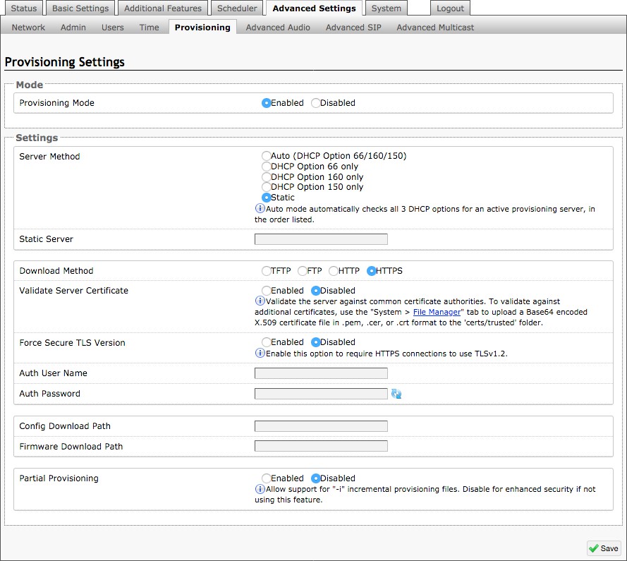
Provisioning can be secured by setting the ‘Download Method’ to ‘HTTPS’ (under the Advanced Settings → Provisioning tab). This prevents configuration files from being read by an unwanted third-party. This resolves the potential risk of having sensitive data stolen, such as admin passwords and SIP credentials.
Note
To verify the server you must ‘Enable’ the ‘Validate Server Certificate’ option. This then checks if the certificate that is provided by the server is signed by any of the CAs included in the list of trusted CAs (used by the Debian infrastructure and Mozilla browsers). If we receive a certificate signed by any of these CAs, then that server will be trusted. Certificates can also be manually uploaded using the ‘File Manager’.
The ‘Validate Server Certificate’ parameter can also be enabled through provisioning: prov.download.cert = 1
SIP Signalling (and RTP Audio)
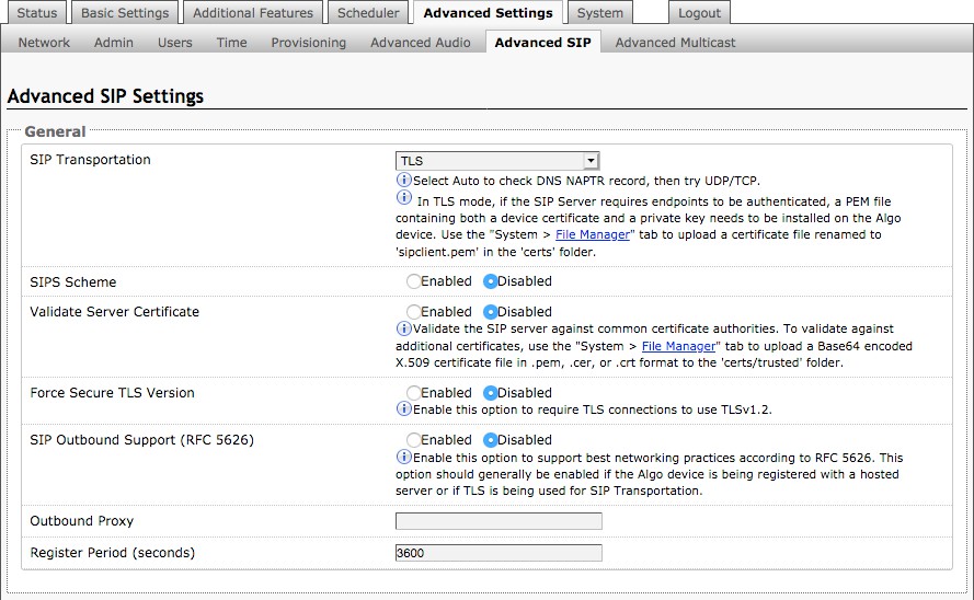
SIP signaling is secured by setting ‘SIP Transportation’ to ‘TLS’ (under the Advanced Settings → Advanced SIP tab). Setting it to ‘TLS’ ensures that the SIP traffic will be encrypted. The SIP signalling is responsible for establishing the call (the control signal to start and end the call with the other party), but it does not contain the audio.
Note
In order for a SIP server to validate the Algo device, an additional certificate may be installed on the Algo device manually. To add the user certificate file use a ‘.pem’, ‘.crt’, or ‘.cer’ filetype extension and have the file named ‘sipclient’. This is done by manually adding a file named ‘sipclient’, which contains a device certificate and private key, to the ‘certs’ folder (under the System → File Manager tab).
Web Interface Status and Login
Web Interface login
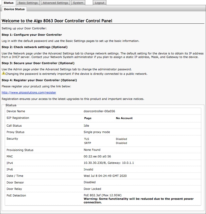
The web interface requires a password which is ‘algo’ by default. This password can be changed using the Admin tab after logging in the first time.
Note
Web Interface is accessed by entering the 8063’s IP Address into a web browser.
It is highly recommended to change the default password if the device is directly connected to a public network.
Status
The device's Status page will be available before and after logon. The section can be used to check the device's SIP Registration status of the SIP Extension, Call Status, Proxy Status, and general MAC, IP, Netmask, Date/Time information.
Note
The Status page can be hidden when logged out for security purposes under the Advanced Settings → Admin tab.
Web Interface Basic Settings
Basic Settings Tab – Basic Configuration
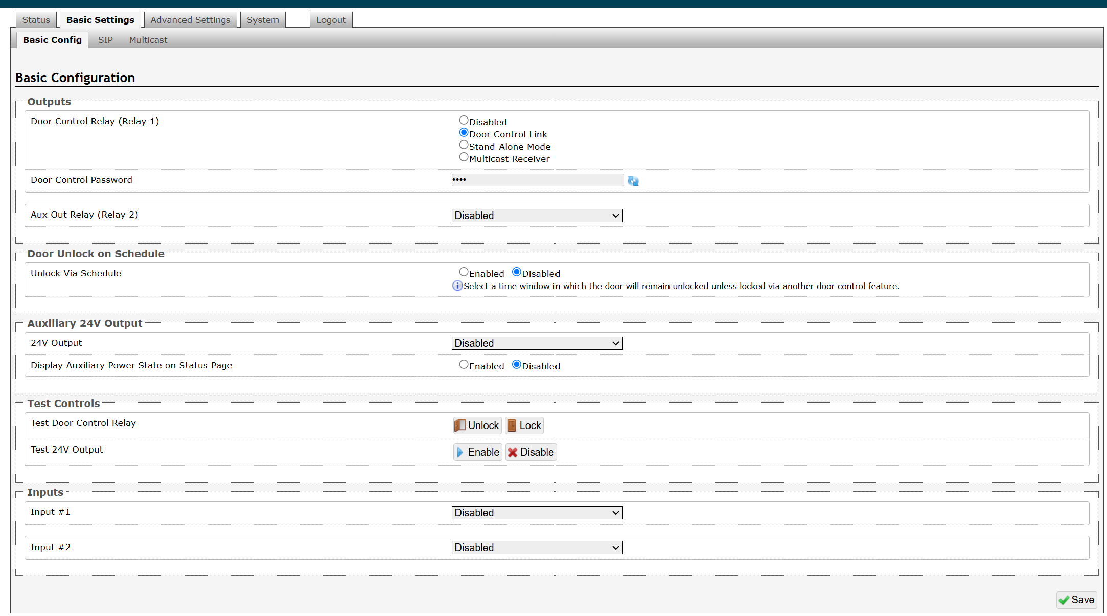
Door Control Relay (Relay 1)
Set the function of the Door Control Relay:
Door Control Link: Uses the 8063 as a Network Door Controller.
Stand-Alone Mode: Operates the 8063 directly from a SIP call without voice communication.
Multicast Receiver: Use the 8063 as a multicast receiver.
Aux Out Relay
Choose what triggers the Aux Out Relay:
Follow Door Control
Follow Input #1
Follow Input #2
Follow Input #1 & #2
Door Alarm
Multicast Receiver
Door Unlock via Inbound Call
Answer Prompt
The prompt tone upon answering of the inbound call to create awareness.
Door Unlock Tone
A tone to be played when the door is unlocked to create awareness.
Momentary Open Code
1-4 digit DTMF code that can be used to unlock the door for a brief period of time. Leave this field blank to disable this feature.
(Default: 6)
Duration
The time period for which to unlock the door when the Momentary Open Code is entered. From ¼ to 30 seconds.
Latch Open Code
Specifies a 1-4 digit code that can be used to unlock the door indefinitely.
Latch Close Code
Specifies a 1-4 digit code that can be used to lock the door indefinitely.
DTMF Detection Type
Different DTMF detection options are given. Use the default of ‘Auto’ unless advised by Algo technical support.
End call on DTMF
Terminate the call 2 seconds after the door control DTMF has been received. This feature only applies to the Momentary Open Code.
Door Unlock on Schedule
Unlock Via Schedule
Select a time window in which the door will remain unlocked unless locked via another door control feature.
Unlock Time
Specifies when to unlock the door.
Lock Time
Specifies when to lock the door.
Days to Apply Schedule
Specifies the days on which the lock and unlock schedule is applied.
Door Open Alarm
Max Door Open
Alarm will be triggered if the door remains open for longer than the selected duration.
Extension to Dial
Set an extension to be dialed when alarm is triggered.
Alarm Tone/Pre-recorded Announcement
Pre-loaded tones or custom loaded tones/recorded announcement can be used as an alarm tone.
Interval Between Tones (seconds)
Set interval between the alarm tones.
Maximum Alarm Duration
Set maximum alarm duration.
Auxiliary 24V Output
24V Output
Set the 24V Output to be Disabled, Always On, or to Follow Door Control. If set to Follow Door Control, then this terminal can be wired directly to the door strike (if compatible), without needing to be also wired through the relay.
Display Auxiliary Power State on Status Page
If enabled, the status of the Auxiliary Power State will be shown on the status page.
Test Controls
Test Door Control Relay: Test the door lock and unlock controls.
Test 24V Output: Enable or disable the 24V output feature.
Inputs
Input #1
Select the Door Sensor (not included) to use the ‘Door Open Alarm’ or ‘Cancel if Door Opened’ function. The Door Sensor can be set to be normally open or normally closed.
Input #2
Another input can be set to Manual Door Release or Door Control Lockout.
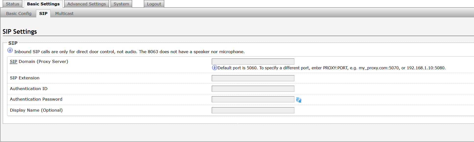
Basic Settings Tab - SIP
SIP Server information and Credentials should be obtained from your telephone system administrator or hosted account provider. After saving the settings, see the Status tab to confirm the registration was successful.
Note
Any time changes are made to settings in the Web Interface the ‘Save’ key must be clicked to save the changes.
SIP Domain (Proxy Server)
The IP address (e.g. 192.168.1.111) or domain name (e.g. myserver.com) of the SIP Server.
SIP Extension
This is the SIP extension for the 8063 IP Door Controller.
Authentication ID
May also be called Username for some SIP servers and in some cases may be the same as the SIP extension.
Authentication Password
SIP password provided by the system administrator for the SIP account.
Display Name
Enter a “Display Name” that will be sent when the SIP call is made. The PBX and phone(s) will have to be configured to display this message as the Caller ID.
Web Interface Advanced Settings
Advanced Settings Tab - Network
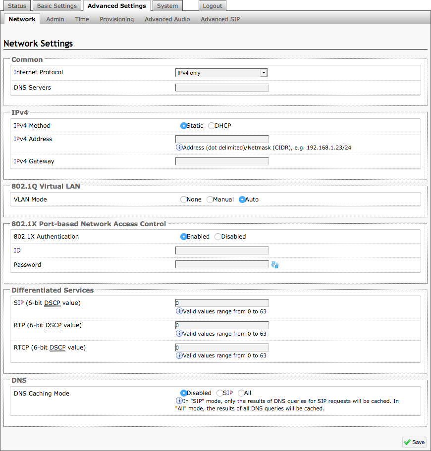
Internet Protocol
The 8063 can be set to have IPv4 only or both IPv4 and IPv6 method as its internet protocol.
IPv4/IPv6 Method
The 8063 can be set to a DHCP or a static IP address. When DHCP is selected, DHCP will automatically configure IP addresses for each 8063 IP Door Controller on the network.
IPv4/IPv6 Address
Enter the static IP address for the 8063.
IPv4/IPv6 Address
Enter the gateway address.
VLAN Mode
Enables or Disables VLAN Tagging. VLAN Tagging is the networking standard that supports Virtual LANs (VLANs) on an Ethernet network. The standard defines a system of VLAN tagging for Ethernet frames and the accompanying procedures to be used by bridges and switches in handling such frames. The standard also provides provisions for a quality of service prioritization scheme commonly known as IEEE 802.1p and defines the Generic Attribute Registration Protocol.
VLAN ID
Specifies the VLAN to which the Ethernet frame belongs. A 12-bit field specifying the VLAN to which the Ethernet frame belongs. The hexadecimal values of 0x000 and 0xFFF are reserved. All other values may be used as VLAN identifiers, allowing up to 4094 VLANs.
The reserved value 0x000 indicates that the frame does not belong to any VLAN; in this case, the 802.1Q tag specifies only a priority and is referred to as a priority tag. On bridges, VLAN 1 (the default VLAN ID) is often reserved for a management VLAN; this is vendor specific.
VLAN Priority
Sets the frame priority level. Otherwise known as Priority Code Point (PCP), VLAN Priority is a 3-bit field which refers to the IEEE 802.1p priority. It indicates the frame priority level. Values are from 0 (lowest) to 7 (highest).
Authentication
Credentials to access LAN or WLAN that have 802.1X network access control (NAC) enabled. This information will be available from the IT Administrator.
Differentiated Services (6-bit DSCP value)
Provides quality of service if the DSCP protocol is supported on your network. Can be specified independently for SIP control packets versus RTP audio packets.
DNS Caching Mode
In “SIP” mode, only the results of DNS queries for SIP requests will be cached. In “All” mode, the results of all DNS queries will be cached.
Admin
Admin settings allow you to configure device access, security, management, monitoring, and integration features.
From this page, you can change administrator credentials, manage logging and network management settings, enable APIs and external services, and configure device maintenance options.
Note
Available settings may vary depending on your product model and firmware version.
To configure Admin settings:
Go to Advanced Settings → Admin.
Configure the settings.
Refer to the following tables for the setting description.
Admin Settings
This section contains settings for administrator credentials, logging and network management, APIs and external services, and device maintenance.
Admin Password | |
Old Password | Enter the old admin password. The default password when you first get the device is algo. |
Password | Enter a new admin password to log into the device web interface. Make sure the new password is stored safely. If the password is forgotten, you must reset the device entirely with the Reset Button to restore the default password. All other settings will be reset to the original default settings as well. |
Confirmation | Re-enter your new admin password. |
General | |
Device Name (Hostname) | Add a name to identify the device. |
Introduction Section on Status Page | Select On to show the introduction text on the login screen. |
Show Status Section on Status Page when Logged Out | Select On to allow others to view the status page without logging in. Select Off to hide the settings and configurations on the status page unless a user is logged in to ensure only trusted users can view device information. |
Display Switch Port ID on Status Page | Select On to display the Switch Port ID on the Status Page. This option is only possible if the device is connected to a switch that supports LLDP or CDP. |
Web Interface Session Timeout | Set the maximum duration of inactivity to log a user out of the web interface automatically. |
Play Tone at Startup | The device can play a beep tone at startup. This option is available only to Algo IP Speakers, IP Displays, Paging Adapters, and IP Consoles. |
Log Settings | |
Log Level | Select the types of information you want to include in the system log files.
|
Log Method | Select a log method: Local: The log file is saved in RAM on the device. Network: Send the log file to an external SysLog server so settings are not lost if the device is rebooted, or for ease of central access. Both: Use both methods. |
Log Server | Enter the Syslog server address provided by your IT administrator. |
Log Additional Log Events | To be used by support@algosolutions.com if necessary. |
Management | |
Web Interface Protocol | HTTPS is always enabled on the device. HTTP is enabled by default but may be disabled. To do so, select HTTPS Only mode so requests are automatically redirected to HTTPS.
|
Force Strong Password | When Enabled, you can enforce a secure password for the device web interface for additional protection. The password requirements for a strong password are:
|
Allow Secure SIP Passwords | When Enabled, SIP passwords are stored in the configuration file in an encrypted format to prevent viewing and recovery. If enabled, navigate to Basic Settings → SIP and fill out the Realm field. To obtain your SIP Realm information, contact your SIP Server administrator or check the SIP log file for a registration attempt. The Realms may be the same or different for all the extensions used. All the configured Authentication Password(s) must be re-entered here as well as any other locations where SIP extensions have been configured to save the encrypted password(s). If the Realm is changed later, all passwords must be re-entered to save the passwords with the new encryption. |
Simple Network Management Protocol | |
SNMP Support | Disabled by default. The existing setting will respond to a simple status query for automated supervision. |
SNMP Community String | Speak to your IT Administrator for more information. |
SNMPv3 Security | Speak to your IT Administrator for more information. |
API Support | |
RESTful API | Disabled by default. Enable a secure API for remote access and device control via HTTP. For more information, see the Algo RESTful API Guide. |
Authentication Method | Speak to your IT Administrator for more information. |
RESTful API Password | Speak to your IT Administrator for more information. |
SCI Support | |
SCI | Disabled by default. Simple Control Interface (SCI) is a separate control interface for certain applications. Its primary purpose is to support phones that may have programmable keys that can only send out HTTP GET requests and allow them to initiate events remotely on an Algo device. |
SCI Password | Enter your SCI password. |
System Integrity | |
System Integrity Checking | Enable this feature to verify that installed system packages have not been tampered with by running a check. Enabling this feature may cause reboots and upgrades to take 30 seconds longer. Verification results can be found on the Status tab. |
Power over Ethernet | |
PoE Power Detection | Use Force PoE+ only when connected to a PoE+ power injector capable of providing 600mA that does not automatically negotiate its power capabilities. Incorrect use of this setting may cause the device to reboot if the power source is not capable of delivering the selected power. |
LLDP Settings | |
Link Layer Discovery Protocol (LLDP) | Enables LLDP to exchange network configuration information with the connected network switch. |
Use LLDP for Power Negotiation | Determines whether the device uses LLDP to communicate its PoE power requirements to the connected network switch. This setting is available only on devices that require a PoE+ power source. |
Note
Disabling Link Layer Discovery Protocol (LLDP) prevents your device from exchanging network configuration information with the connected network switch. If you are using a VLAN, make sure Link Layer Discovery Protocol (LLDP) is enabled, or that the VLAN Mode (under Advanced Settings → Network Settings) is set to Manual so you can configure VLAN settings manually.
Intrado Revolution (formerly Syn-Apps) | |||
Revolution Support | Enable the device to register with an Intrado Revolution Server and receive audio events from the system. | ||
Revolution Server | Enter the Revolution Server to use the Revolution paging feature. Leave the field blank to use the server provided by the DHCP Option 72 | ||
Local Management Port | Enter the local management port for the Revolution Server. | ||
InformaCast IP Speaker Enable your device to register as an InformaCast SIP endpoint. This allows it to initiate and receive SIP calls and receive messages through InformaCast. | |
InformaCast IP Speaker Support | This feature requires a valid InformaCast license to be activated. Please contact sales@algosolutions.com for assistance. |
Configuration Mode | Auto: The device will attempt to configure Informacast using DNS SRV, SLP, and/or via DHCP and TFTP Manual: The device will allow the configuration file location to be manually configured. Direct: The device will register to the list of static server addresses directly, bypassing the Configuration File Server |
Configuration Retry Interval | Set the amount of time to wait before attempting to obtain configuration information after failure. |
SIP Support | Enter the SIP credentials provided by InformaCast during configuration. |
Maximum Broadcast Duration | The maximum length of broadcast. |
Note
For more information, see Singlewire InformaCast Integration Guide.
InformaCast Scenarios API | |
InformaCast Scenario API Support | Enable the device to start an InformaCast Scenario via relay input. This feature can work without an InformaCast license, as only the output device requires a license. |
Security Token | Enter the Security Token used for authenticating API requests with the InformaCast system. |
Include Location | Enable this option to include the device’s location in the scenario trigger request. |
Microsoft | |
Microsoft Teams Support | Enable to allow the device to register with a Microsoft Teams account. The device reboot will take up to 5 minutes to complete, as the device will communicate several times with the Microsoft server. This feature requires a compatible release from Microsoft. After enabling this setting, please return to the Status page to sign into your Teams accounts. This feature requires a compatible release from Microsoft. For more details, please see the Microsoft Teams Configuration Guide. |
ADMP Cloud Monitoring | |
Enable ADMP Cloud Monitoring | The Algo Device Management Platform (ADMP) simplifies the process of managing, monitoring, and maintaining Algo devices from any location. This feature requires a valid Account ID. To learn more about ADMP and how to purchase a license, visit the ADMP webpage. |
Account ID | Enter the account ID listed on the Settings page of your ADMP account. |
Allow Configuration File Sync | Enable ADMP to query and display settings stored on the device. |
Heartbeat Interval | Select how often ADMP should check the status of your device. |
Enable Panic Button Monitoring | Enable to monitor Panic Button status in ADMP, including:
|
Advanced Settings Tab – Time
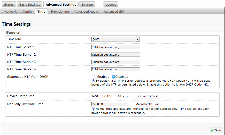
Network time is used for logging events into memory for troubleshooting.
Time Zone
Select time zone.
NTP Time Servers 1/2/3/4
The adapter will attempt to use Timer Server 1 and work down the list if one or more of the time servers become unresponsive.
NTP Time Server Source
When “Use DHCP Option 42” is chosen, if an NTP Server address is provided via the DHCP Option 42, that NTP Server will be used instead of the 4 mentioned above.
Alternatively, “Ignore DHCP Option 42” can be chosen to only use servers mentioned above.
Device Date/Time
This field shows the current time and date as set on the device. If testing the device on a lab network that may not have access to an external NTP server, the “Sync with browser” button can be used to temporarily set the time on the device.
Note
This time value will be lost at power down, or overwritten if NTP is currently active. Time and date are used for logging purposes.
Advanced Settings Tab – Provisioning
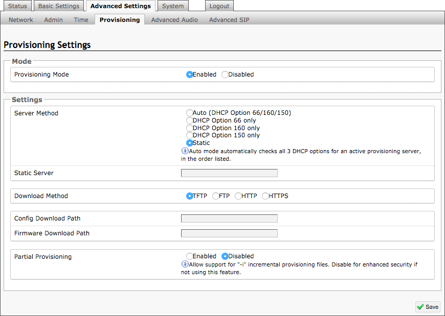
Note
It is recommended that Provisioning Mode be set to Disabled if this feature is not in use. This will prevent unauthorized re-configuration of the device if DHCP is used.
Provisioning allows installers to pre-configure 8063 IP Door Controller units prior to installation on a network. It is typically used for large deployments to save time and ensure consistent setups.
The device can be provisioned via the Auto mode (where all three DHCP options (Option 66/160/150) will be automatically checked for an active provisioning server), just one of the three specified DHCP options, or a Static Server. In addition, there are four different ways to download provisioning files from a “Provisioning Server”: TFTP (Trivial File Transfer Protocol), FTP, HTTP, or HTTPS.
For example, the 8063 configuration files can be automatically downloaded from a TFTP server using DHCP Option 66. This option code (when set) supplies a TFTP boot server address to the DHCP client to boot from.
Note
DHCP must be enabled if using DHCP Option 66/160/150, in order for Provisioning to work.
One of two files can be uploaded on the Provisioning Server (for access via TFTP, FTP, HTTP, or HTTPS):
Generic (for all 8063 IP Door Controller) algop8063.conf
Specific (for a specific MAC address) algom[MAC].conf
Both protocol and path is supported for Option 66, allowing for http://myserver.com/config-path to be used.
MD5 Checksum
In addition to the .conf file, an .md5 checksum file must also be uploaded to the Provisioning server. This checksum file is used to verify that the .conf file is transferred correctly without error.
A tool such as can be found at the website address below may be used to generate this file: http://www.fourmilab.ch/md5
The application doesn’t need an installation. To use the tool, simply unzip and run the application (md5) from a command prompt. The proper .md5 file will be generated in the same directory.
If using the above tool, be sure to use the “-l” parameter to generate lower case letters.
To generate a generic configuration file
Connect the 8063 to the network.
Access the 8063 Web Interface Control Panel.
Configure the 8063 with desired options.
Click on the System tab and then Maintenance.
Click “Download” to download the current configuration file.
Save the file settings.txt.
Rename file settings.txt to algop8063.conf.
File algop8063.conf can now be uploaded onto the Provisioning server.
If using a generic configuration file, extensions and credentials have to be entered manually once the 8063 IP Door Controller has automatically downloaded the configuration file.
To generate a specific configuration file
Follow steps 1 to 6 as listed in the section “Generating a generic configuration file”.
Rename file settings.txt to algom[MAC address].conf (e.g. algom0022EE020009.conf)
File algom[MAC address].conf can now be uploaded on the Provisioning server.
The specific configuration file will only be downloaded by the 8063 IP Door Controller with the MAC address specified in the configuration file name. Since all the necessary settings can be included in this file, the 8063 will be ready to work immediately after the configuration file is downloaded. The MAC address of each 8063 IP Door Controller can be found on the back label of the unit.
For more Algo SIP endpoint provisioning information, see: www.algosolutions.com/provision
Using OAuth for Authentication
OAuth (Open Authorization) is an industry-standard protocol that enables secure, delegated access to resources without requiring users to share credentials such as usernames and passwords.
Instead of storing static credentials on a device or application, OAuth allows a trusted third-party service (such as Google, Microsoft, or Slack) to issue time-limited access tokens. These tokens allow an Algo device to interact with the service on behalf of a user or system, without exposing sensitive login information.
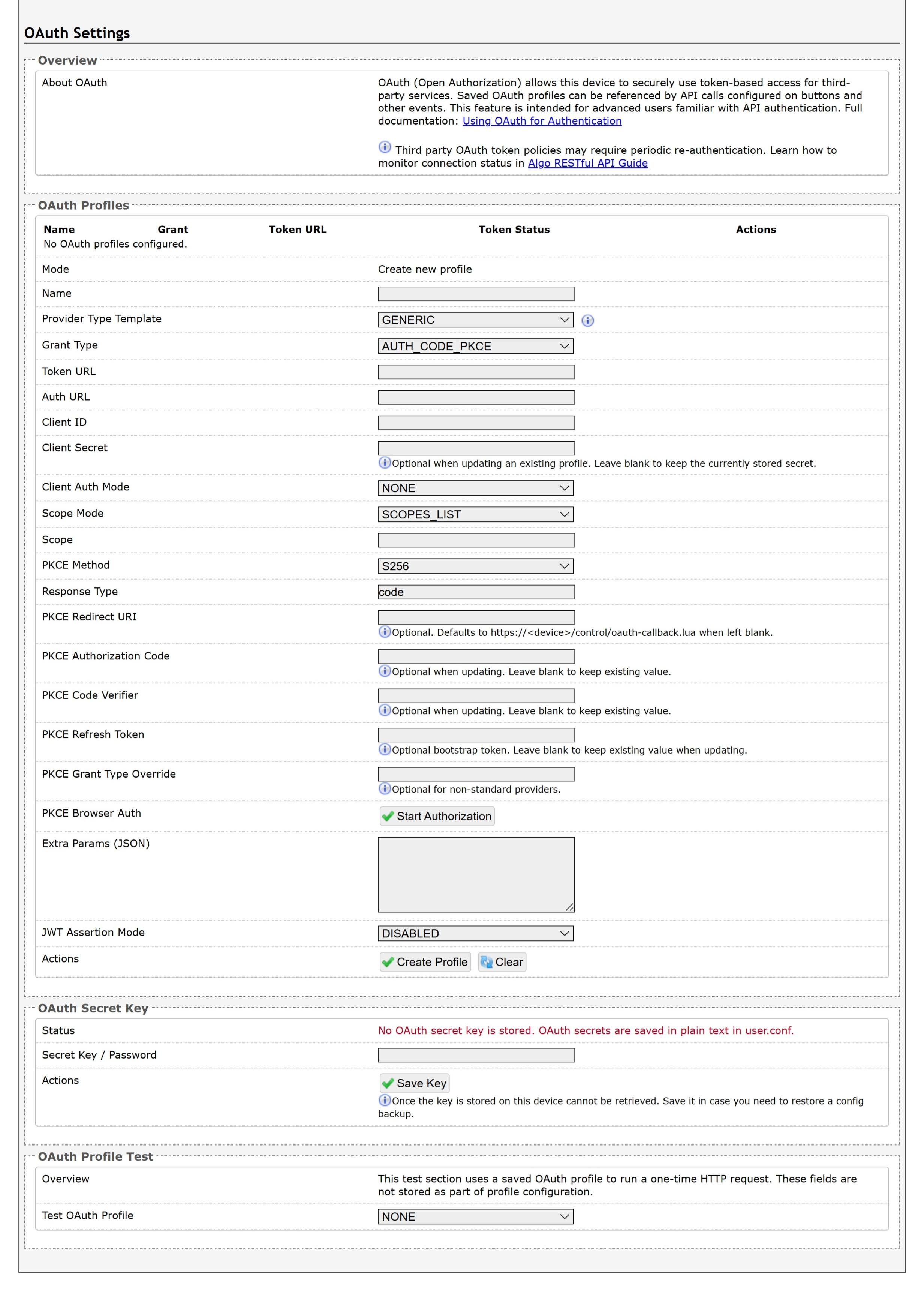
For more information, see Using OAuth for Authentication.
Advanced Settings Tab – Advanced Audio
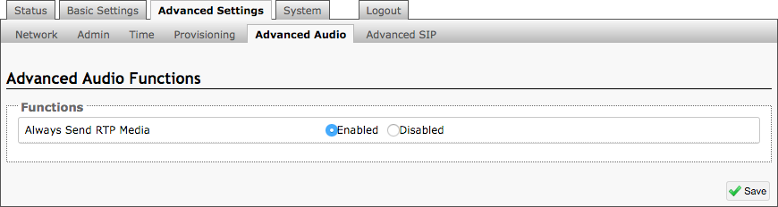
Always Send RTP Media
If enabled, audio packets will be sent at all times. This option is needed in cases when the server expects to see audio packets at all times.
Advanced Settings Tab – Advanced SIP
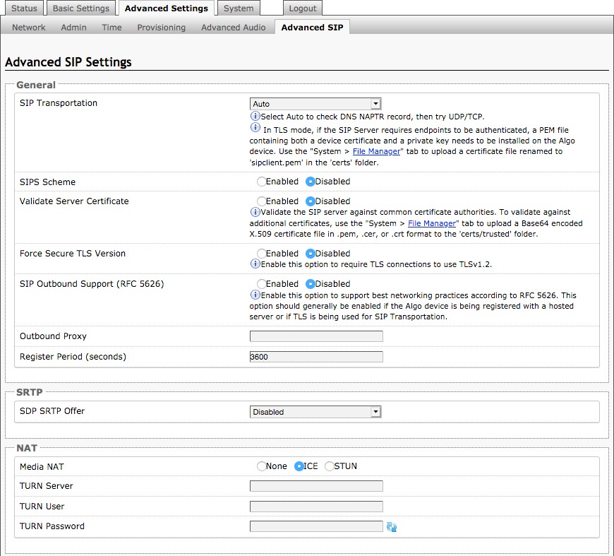
SIP Transportation
Selects the transport layer protocol to use for SIP messages. Setting ‘SIP Transportation’ to ‘TLS’, ensures the encryption of SIP traffic.
SIPS Scheme
Only visible when ‘SIP Transportation’ set to ‘TLS’. Enabling SIPS Scheme requires the SIP connection from endpoint to endpoint to be secure.
SDP SRTP Offer
Setting ‘SDP SRTP Offer’ to ‘Optional’, means the SIP call’s RTP data will be left unencrypted if the other party does not support SRTP. Setting ‘SDP SRTP Offer’ to ‘Standard’, encrypts RTP voice data, meaning the normal audio RTP packets will now be secure (SRTP). This means SIP calls will be rejected if other party does not support SRTP. The ‘Standard’ option secures the audio data between parties, by making sure that it’s not left out in the open for third parties to later reconstruct and listen to.
SIP Outbound Support (RFC 5626)
Enable this option to support best networking practices according to RFC 5626. This option should generally be enabled if the Algo device is being registered with a hosted server or if TLS is being used for SIP Transportation.
Outbound Proxy
IP address for outbound proxy. A proxy (server) stands between a private network and the internet.
Register Period (seconds)
Maximum requested period of time where the 8063 IP Door Controller will re-register with the SIP server. Default setting is 3600 seconds (1 hour). Only change if instructed otherwise.
Media NAT
IP address for STUN server if present or IP address/credentials for a TURN server.
Server Redundancy Feature
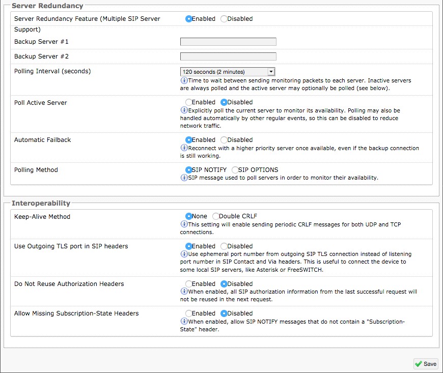
Two secondary SIP servers may be configured. The 8063 IP Door Controller will attempt to register with the primary server but switch to a secondary server when necessary.
The configuration allows re-registration to the primary server upon availability or to stay with a server until unresponsive.
If Server Redundancy is selected the web page will expand as shown below.
Backup Server #1
If the primary server is unreachable the 8063 IP Door Controller will attempt to register with the backup servers. If enabled, the 8063 will always attempt to register with the highest priority server.
Backup Server #2
If backup server #1 is unreachable the 8063 IP Door Controller will attempt to register with the 2nd backup server. If enabled, the 8063 will always attempt to register with the highest priority server.
Polling Intervals (seconds)
Time period between sending monitoring packets to each server. Non-active servers are always polled, and active server may optionally be polled (see below).
Poll Active Server
Explicitly poll current server to monitor availability. May also be handled automatically by other regular events, so can be disabled to reduce network traffic.
Automatic Failback
Reconnect with higher priority server once available, even if backup connection is still fine.
Polling Method
SIP message used to poll servers to monitor availability.
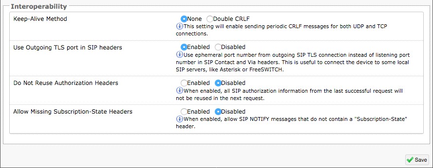
Use Outgoing TLS port in SIP headers
Use ephemeral port number from outgoing SIP TLS connection instead of listening port number in SIP Contact and Via headers. This is useful to connect the device to some local SIP servers, like Asterisk or FreeSWITCH.
Do Not Reuse Authorization Headers
When enabled, all SIP authorization information from the last successful request will not be reused in the next request.
Web Interface System
System Tab – Maintenance
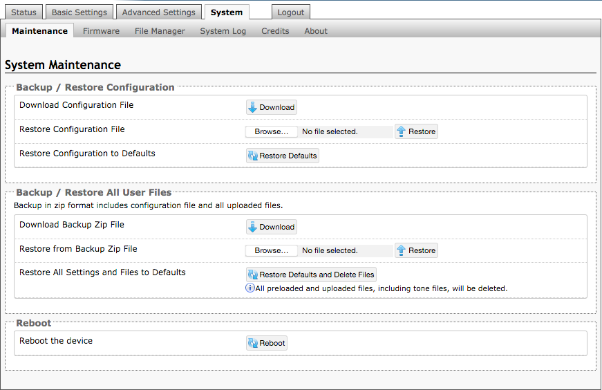
Download Configuration File
Save the device settings to a text file for backup or to setup a provisioning configuration file.
Restore Configuration File
Restore settings from a backup file.
Restore Configuration to Defaults
Resets all 8063 IP Door Controller device settings to factory default values.
Download Backup File
Saves the device settings (configuration) and all the files in File Manager: certificates, licenses, and tones to a backup zip file.
Restore from Backup Zip File
Restores the device settings (configuration) and all the files in File Manager: certificates, licenses, and tones from a backup zip file
Restore All Settings and Files to Defaults
Resets the device settings (configuration) and all the files in File Manager: certificates, licenses, and tones to factory default values.
Reboot the Device
Reboots the device.
System Tab – Firmware
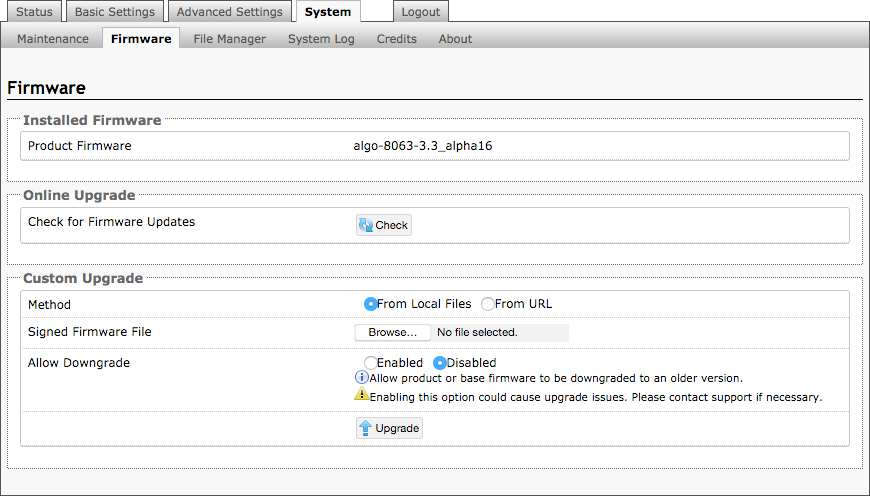
Method
Specify whether the firmware files will be downloaded from the local computer or a remote URL.
Signed Firmware Image
Point to the signed firmware image provided by Algo.
Allow Downgrade
Allow the 8063 to be downgraded to an older version. Please be advised that downgrades are supported only between same main version. For more information contact Algo Support.
To upgrade 8063 IP Door Controller Firmware:
From the top menu, click on System, then Maintenance.
In the Upgrade section, click on Choose File and select the 8063 IP Door Controller firmware file to upload.
Note
A .SFW file must be loaded.
Click Upgrade.
After the upgrade is complete, confirm that the firmware version has changed (refer to the top-right of the Control Panel).
System Tab – File Manager
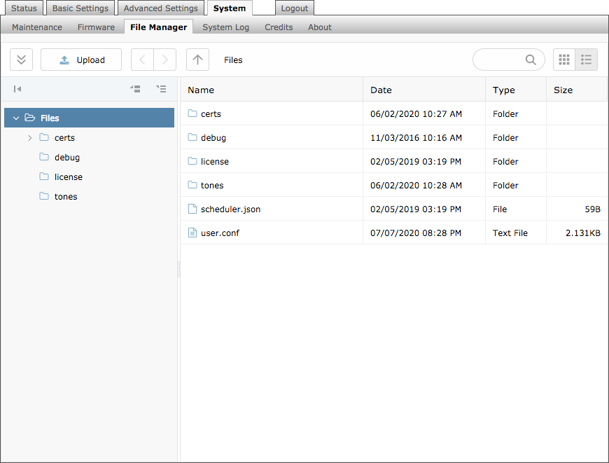
File Formats
When uploading files to the File Manager, refer to this table for supported file formats and requirements.
Folder | Supported Format | Requirements |
|---|---|---|
License | LIC | |
Tones | 8SVX, AIF, AIFC, AIFF, AIFFC, AL, AMB, AMR-NB, AMR-WB, ANB, AU, AVR, AWB, CAF, CDDA, CDR, CVS, CVSD, CVU, DAT, DVMS, F32, F4, F64, F8, FAP, FLAC, FSSD, GSM, GSRT, HCOM, HTK, IMA, IRCAM, LA, LPC, LPC10, LU, MAT, MAT4, MAT5, MAUD, MP2, MP3, NIST, OGG, PAF, PRC, PVF, RAW, S1, S16, S2, S24, S3, S32, S4, S8, SB, SD2, SDS, SF, SL, SLN, SMP, SND, SNDFILE, SNDR, SNDT, SOU, SOX, SPH, SW, TXW, U1, U16, U2, U24, U3, U32, U4, U8, UB, UL, UW, VMS, VOC, VORBIS, VOX, W64, WAV, WAVPCM, WV, WVE, XA, XI | Audio files must be in the following format:
|
Certs Folder
If you have enabled Validate Server Certificate under Advanced Settings →Advanced SIP or Advanced Settings → Provisioning and want to validate against additional certificates, you can upload them here.
To install a public CA certificate on the Algo device:
Obtain a public certificate from your Certificate Authority (Base64 encoded X.509 .pem, .cer, or .crt).
Open the certs folder in the web interface by going to System → File Manager.
Upload the certificate files into the certs folder by clicking Upload in the top left corner of the file manager and select the certificate.
Reach out to support@algosolutions.com to get the complete list of pre-loaded trusted certificates.
Debug Folder
If you have any challenges with the device and work with the Algo support team to overcome or fix them, the debug folder will be used. The device will generate files containing information about the device and put them in the debug folder. You do not need to use this folder unless directed to by the Algo support team.
License Folder
If you would like to use InformaCast on a device that hasn't been bundled with an InformaCast license, you will need to purchase a license and put it into the license folder in the file manager.
Tones Folder
Custom audio files may be uploaded to play notifications. Audio files should be stored in the tones directory.
Existing files may be modified by downloading the original file, making the desired changes, then uploading the updated file with a different name.
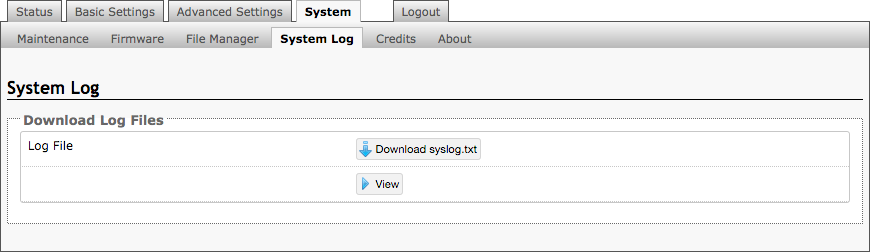
System Tab – System Log
System log files are automatically created and assist with troubleshooting in the event the 8063 IP Door Controller does not behave as expected.
FCC Compliance Statement
This equipment has been tested and found to comply with the limits for a Class A digital device, pursuant to Part 15 of the FCC Rules. These limits are designed to provide reasonable protection against harmful interference when the equipment is operated in a commercial environment. This equipment generates, uses, and can radiate radio frequency energy, and if it is not installed and used in accordance with the instruction manual, it may cause harmful interference to radio communications. Operation of this equipment in a residential area is likely to cause harmful interference, in which case the user will be required to correct the interference at their own expense.