Disclaimer
The information contained in this document is believed to be accurate in all respects but is not warranted by Algo. The information is subject to change without notice and should not be construed in any way as a commitment by Algo or any of its affiliates or subsidiaries. Algo and its affiliates and subsidiaries assume no responsibility for any errors or omissions in this document. Revisions of this document or new editions of it may be issued to incorporate such changes. Algo assumes no liability for damages or claims resulting from any use of this manual or such products, software, firmware, and/or hardware.
No part of this document can be reproduced or transmitted in any form or by any means – electronic or mechanical – for any purpose without written permission from Algo.
For additional information or technical assistance in North America, please contact Algo’s support team:
1-604-454-3792
support@algosolutions.com
Important Warning and Safety Information

Important Notice
This product is powered by a certified limited power source (LPS), Power over Ethernet (PoE); through CAT5 or CAT6 connection wiring to an IEEE 802.3at / 802.3bt compliant network PoE switch. The product is intended for installation indoors. All wiring connections to the product must be in the same building. If the product is installed beyond the building perimeter or used in an inter-building application, the wiring connections must be protected against overvoltage/transient. Algo recommends that this product is installed by a qualified electrician.
If you are unable to understand the English language safety information, then please contact Algo by email for assistance before attempting an installation support@algosolutions.com.
Consignes de Sécurité Importantes
Ce produit est alimenté par une source d’alimentation limitée certifiée (alimentation par Ethernet); des câbles de catégorie 5 et 6 joignent un commutateur réseau à alimentation par Ethernet homologué IEEE 802.3at / 802.3bt Le produit est conçu pour être installé à l’intérieur. Tout le câblage rattaché au produit doit se trouver dans le même édifice. Si le produit est installé au-delà du périmètre de l’édifice ou utilisé pour plusieurs édifices, le câblage doit être protégé des surtensions transitoires. Algo recommande qu’un électricien qualifié se charge de l’installation de ce produit.
Si vous ne pouvez comprendre les consignes de sécurité en anglais, veuillez communiquer avec Algo par courriel avant d’entreprendre l’installation au support@algosolutions.com.
Información de Seguridad Importante
Este producto funciona con una fuente de alimentación limitada (Limited Power Source, LPS) certificada, Alimentación a través de Ethernet (Power over Ethernet, PoE); mediante un cable de conexión CAT5 o CAT6 a un conmutador de red con PoE en cumplimiento con IEEE 802.3at / 802.3bt. El producto se debe instalar en lugares cerrados. Todas las conexiones cableadas al producto deben estar en el mismo edificio. Si el producto se instala fuera del perímetro del edificio o se utiliza en una aplicación en varios edificios, las conexiones cableadas se deben proteger contra sobretensión o corriente transitoria. Algo recomienda que la instalación de este producto la realice un electricista calificado.
Si usted no puede comprender la información de seguridad en inglés, comuníquese con Algo por correo electrónico para obtener asistencia antes de intentar instalarlo: support@algosolutions.com.
Wichtige Sicherheitsinformationen
Dieses Produkt wird durch eine zertifizierte Stromquelle mit begrenzter Leistung (LPS – Limited Power Source) betrieben. Die Stromversorgung erfolgt über Ethernet (PoE – Power over Ethernet). Dies geschieht durch eine Cat-5-Verbindung oder eine Cat-6- Verbindung zu einer IEEE 802.3at / 802.3bt-konformen Ethernet-Netzwerkweiche. Das Produkt wurde konzipiert für die Installation innerhalb eines Gebäudes. Alle Kabelverbindungen zum Produkt müssen im selben Gebäude bestehen. Wenn das Produkt jenseits des Gebäudes oder für mehrere Gebäude genutzt wird, müssen die Kabelverbindungen vor Überspannung und Spannungssprüngen geschützt werden. Algo empfiehlt das Produkt von einem qualifizierten Elektriker installieren zu lassenv.
Sollten Sie die englischen Sicherheitsinformationen nicht verstehen, kontaktieren Sie bitte Algo per Email bevor Sie mit der Installation beginnen, um Unterstützung zu erhalten. Algo kann unter der folgenden E-Mail-Adresse erreicht werden: support@algosolutions.com.
安全须知
本产品由认证的受限电源(LPS),以太网供电(PoE),通过 CAT5 或 CAT6 线路联接至 IEEE 802.3at / 802.3bt 兼容的 PoE 网络交换机供电。本产品适用于室内或建筑物周边安装。所有联 接本产品的线路必须源自同一建筑物。本产品如需用于超出建筑物周边范围或跨建筑物的安 装,线路联接部分必须有过压和瞬态保护。Algo 建议本产品由专业电工安装。
如果您对理解英文版安全须知有问题,安装前请通过电子邮件和 Algo 联 系. support@algosolutions.com.
INSTALLATION
An improperly installed 8410 IP Display Speaker or 8420 IP Dual-Sided Display Speaker could fall from a wall or ceiling and cause serious injury or death.
Local building code may require one or more additional safety measure(s), particularly in earthquake prone regions.
EMERGENCY COMMUNICATION
If used in an emergency communication application, the 8410 IP Display Speakers and 8420 IP Dual-Sided Display Speaker should be routinely tested. SNMP supervision is recommended for assurance of proper operation. Contact Algo for other methods of operational assurance.
DRY INDOOR LOCATION ONLY
The 8410 IP Display Speaker and 8420 IP Dual-Sided Display Speaker is intended for dry indoor locations only. For outdoor locations, Algo offers weatherproof speakers and strobe lights.
CAT5 or CAT6 connection wiring to an IEEE 802.3at (PoE+) or IEEE 802.3 bt (PoE++) compliant network PoE switch must not leave the building perimeter without adequate lightning protection.
No wiring connected to the 8410 IP Display Speaker and 8420 IP Dual-Sided Display Speaker may leave the building perimeter without adequate lightning protection.
General
Introduction
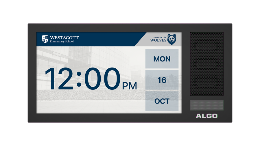
Algo’s 8410 IP Display Speaker is a SIP-compliant notification device that comprises of three core components – LCD screen, Wideband Speakers, and LED flashers – to create highly flexible and effective visual and audible communication. The combined functionality of the LCD display screen, speakers, and flashing LEDs enable voice paging, visual or audible alerting, and informational visual content, such as scrolling text messages, visual paging, images, or wayfinding. Two-way communication can also be established through the embedded microphone so real-time updates can easily be provided to admin staff. When idle, the Display Speakers can display an image, a clock face (shown in analog and/or digital format and synchronized to network time protocol (NTP)), rotating through a variety of announcements, or go to sleep.
The 8420 IP Dual-Sided IP Display Speaker has all the core components of the 8410 but is double-sided. The two-sided functionality of the 8420 is ideal for installation in corridors, large spaces, or hallways for easy opposite-facing visual and audible communication.
As 3rd-party, SIP-compliant devices, the 8410/8420 is designed to seamlessly integrate into most leading IP-based UC and Mass Notification platforms. The 8410/8420 is easily configured using central provisioning features or by accessing the web interface using your choice of browser.
Key Features
LCD Screen
The primary element of the 8410/8420 is the LCD screen(s). With nearly unlimited visual possibilities, the screen can produce scrolling text, flashing announcements, full-color images, or times and dates. Combined with LED backlighting and wide-angle viewing, the visual display can be seen from anywhere in a room or along a hallway. It can be customized to complement an audio announcement or to bring communication to an audio-less environment.
Speakers
For audible alerting and voice paging, the 8410/8420 offers similar functionality and voice quality to other Algo IP speakers, delivering wideband HD voice for clear voice communication and attention-grabbing audible alerting. An embedded microphone is included to enable ambient noise response and talkback capabilities.
LED Flashers
The LED flashers provide additional awareness for important messages. This can help draw attention to the screen, helping hearing-impaired audiences to notice the screen or bring awareness to audio-less environments.
Setup and Installation for 8410 and 8420
Important
This guide provides important safety information which should be read thoroughly before permanently installing the product.
See the appropriate section below for mounting either the 8410/8420.
8410 Mounting & Installation
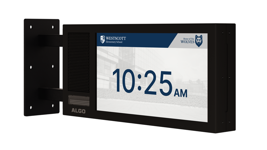
Algo’s 8410 IP Display Speaker is a one-sided product intended for mounting on a wall. For the ceiling-mount option more suited to hallways, see the 8420 mounting and installation instructions below.
What is Included The following items are included with the purchase of this device:
| What is Not Included The following items are not included with the purchase of this device:
|
Getting Started – Quick Install and Setup
Connect the 8410 to an IEEE 802.3at / 802.3bt compliant PoE+ or PoE++ network switch or power injector. See section 2.4 Power Requirements.
The green LED flashers will activate and a small blue light on the bottom below the flasher will remain on until boot up is completed – about one minute.
After a few moments, the screen will show the Algo logo.
Warning
PoE++ power is required for optimal operation of this device. Some functionality will be reduced depending on the power connection.
If using a power injector that does not automatically negotiate its power capabilities, go to Advanced Settings → Admin to manually configure Automatic Power Detection versus Forced PoE+ mode.
Attach the snap-on ferrite to the Ethernet cable close to the connector.
Once the unit finishes booting, a configuration message with the IP address will appear on the screen if it is in factory default state. If there is no DHCP server, the 8410 will default to the static IP address 192.168.1.111.
Note
If the IP address does not appear on the screen, press the reset (RST) button to hear the IP address recited over the speakers. The IP address will be repeated over the speakers until the reset button is pressed again to turn off.
Access the 8410 IP Display Speaker web interface by entering the IP address into a browser and login using the default password algo.
Installation
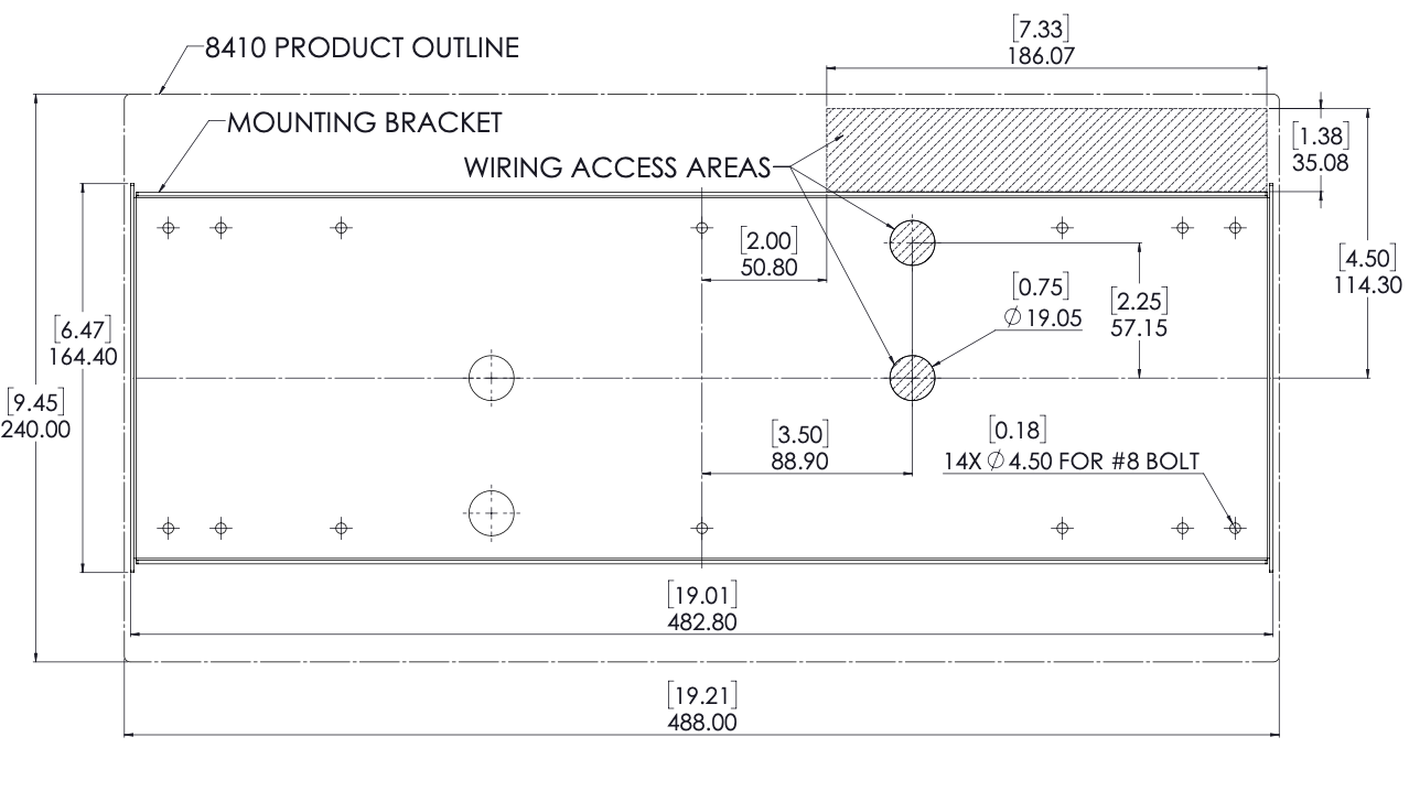
The 8410 IP Display Speaker is designed to fit on a wall bracket. Concealed wiring may enter from the wall into the wiring cavity. Alternatively, surface wiring may enter through a channel from the bottom edge.
To mount the wall bracket securely:
Use four #8 wall bracket screws to hang the wall bracket. The wall-mount bracket should be secured to a stud to prevent the 8410 from falling.
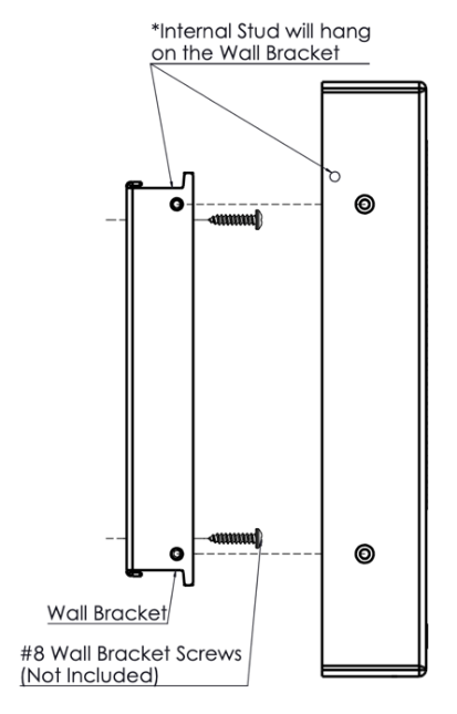
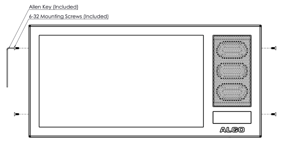
To attach the 8410 to the wall-mount bracket:
Set the 8410 into the wall-mount bracket.
Align the holes on the side of the 8410 to the holes in the wall-mount bracket and tighten the four 6-32 mounting screws securely using the Allen key.
|
|
8420 Mounting & Installation
Algo’s 8420 IP Dual-Sided Display Speaker is a two-sided SIP-compliant notification device that can be mounted on the ceiling or wall for two-sided visual communication. This is ideally suited for hallways, corridors, or open spaces.
What is Included The following items are included with the purchase of this device:
| What is Not Included The following items are not included with the purchase of this device:
|
Getting Started – Quick Install & Test
Connect the 8420 to an IEEE 802.3at / 802.3bt compliant PoE+ or PoE++ network switch or power Injector. See section 2.4 Power Requirements.
The green LED flashers will activate and a small blue light on the bottom below the flasher will remain on until boot up is completed – about 30 seconds.
After a few moments, the screens on either side will show the Algo logo.
Attach the snap-on ferrite to the Ethernet cable close to the connector.
Once the unit finishes booting, a configuration message with the IP address will appear on each screen if it is in factory default state. If there is no DHCP server, the 8420 will default to the static IP address 192.168.1.111.
Note
If the IP address does not appear on the screen, press the reset (RST) button to hear the IP address recited over the speakers. The IP address will be repeated over the speakers until the reset button is turned off.
Access the 8420 IP Dual-Sided Display Speaker web interface by entering the IP address into a browser and logging in using the default password algo.
Installation
The 8420 IP Dual-Sided Display Speaker is designed to be both ceiling and wall mounted. Wiring enters through an opening in the hollow bracket for this product (see info in the Note after bullet 1 below).
To mount the bracket securely to the wall/ceiling:
Mount the bracket securely to a wall or ceiling. Because the material you mount the device into may differ, see below for specific wall or ceiling mount instructions by material type.
Note
Wires can be routed into the hollow tubes of the bracket from the wall/ceiling or through the wire feed hole outside the tube. Wire must be routed on the same side as the speakers to match the connection area.
Set the 8420 into the mounting bracket by partially threading the screws into the holes next to the connector opening and mount the screws through the larger hole of the keyhole slot. Slide the 8420 into the smaller holes to lock the device in place.
Slide the ceiling- or wall-mount connector cover into place.
Fasten all six mounting screws on the bracket and the two flat mounting screws on the connector cover.
.png)
.png)
8420 Wall Mount
For concrete, brick, or block install, use 6 x 5/16” x 1 5/8” female threaded anchors rated for 200 lbs each or greater pull and install bracket using 6 x 1 ½” grade 5 threaded bolts with flat washer.
For plaster or drywall install, use 6 x 5/16” toggle bolts and washers rated for 60 lbs each or greater. The bolts with a washer should be fed through the bracket prior to attaching toggles. If a wood stud is available and the position is known, use 5/16” x 2 ½” lag bolts in place of toggle bolts on the side of the bracket aligned to the stud.
8420 Ceiling Mount
For concrete install, use 6 x 5/16” x 1 5/8” female threaded anchors rated for 200 lbs each or greater pull and install the bracket using 6 x 1 ½” grade 5 threaded bolts with flat washer.
For plaster or drywall install, use 6 x 5/16” toggle bolts and washers rated for 60 lbs each or greater. The bolts with a washer should be fed through the bracket prior to attaching toggles. If a wood joist is available and the position is known, use 5/16” x 2 ½” lag bolts in place of toggle bolts on the side of the bracket aligned to the joist.
For acoustic tile, cut and lay 3/4” plywood equal in size dimension to the tile and install the bracket using 6 x 5/16” x 2 ½” lag bolt with a washer.
Making Your First Configuration
To enable a clock:
Navigate to Display → Slides to create a screen display.
Enter a Name and select Digital Clock. Customize your clock preferences. Press Save.
Go to Display → Screens to apply a screen display.
Under Default Screen, select the name of the display created in the previous step from the Slides dropdown menu.
Press Save at the bottom right of the page.
Power Requirements
For optimal performance, Algo recommends using an 802.3bt Type 3 (PoE++) switch for the 8410 and 802.3bt Type 4 (PoE++) switch for the 8420. The minimum power required for the 8410 is 802.3at (PoE+) power and the minimum power required for the 8420 is 802.3bt Type 3 power. If optimal switches are not available, a power injector may be used. If using a power injector that does not automatically negotiate its power capabilities, go to Advanced Settings → Admin to manually configure Automatic Power Detection versus Forced PoE++ mode.
Reset
A recessed reset button (RST) is located at the bottom of the device below the speaker and can only be used to reset the 8410 IP Display Speaker and 8420 IP Dual-Sided Display Speaker at time of power up. To return all the settings to the factory default for the 8410/8420, reboot or power cycle the 8410/8420. Wait until the SIP LED flashes and then press and hold the reset button until the single blue LED on the bottom of the device begins a double flash pattern. Release the reset button and allow the unit to complete its boot process.
Note
Do not press the reset button until the blue SIP LED begins flashing.
A reset will set all configuration options to factory default including the login password.
Once booting has completed, pressing the reset button will cause the device to speak its IP address over the speakers.
Applications
Voice Paging
The 8410 and 8420 can be used for direct paging in addition to multicast. This allows direct communication with a single location.
Notification
The 8410 and 8420 provide effective notification alerting for emergency (e.g., lockdown, evacuation, reverse evacuation), safety (e.g., medical, workplace accident), and security (e.g., OSHA or similar workplace regulations) events.
For emergency alerting, the LCD screen, speaker, and LED flashers can be used together for a highly visible, attention-grabbing communication.
Visual Communication
When not used to display an active alert, the LCD screen can be configured to display a chosen image or layout for when in idle mode. This screen display can be a digital or analog clock synchronized to NTP, or an uploaded image. It can also display a series of selected images in a slideshow.
Multicast Receiver
The 8410 and 8420 are ideal for use as multicast receivers. Each alert can be mapped to multicast zones which can be associated with a display on the LCD screens to complement the audio announcements.
Scheduling
The 8410 and 8420 can be paired with the 8301 IP Paging Adapter (sold separately) for scheduling tones and bells for schools, automated announcements for retail and healthcare, and workplace shift changes and breaks in warehouses.
InformaCast Compatible
The 8410 and 8420 are fully compliant with Singlewire InformaCast for telephone, security, and emergency alerting. They can display scrolling text and audible notifications for safety and security communication.
Features
Setting Up Visual Display Content
The display on the 8410/8420 is completely customizable.
To set up the display screen:
Go to Basic Settings → Screen.
Under Default Screen, choose the following screen settings:
Number of Images
Images
Text Behavior
Text
Text Font
Text Position
Text Color
Text Size
Strobe Flash Pattern
To set the idle screen:
Go to Basic Settings → Features.
Under the Screen heading, select an Idle Pattern and choose the Screen Brightness.
SIP Paging: One 8410/8420
The 8410/8420 can be registered as a third-party SIP extension with a hosted or enterprise Communications Server supporting 3rd-party SIP endpoints.
To register the 8410/8420 with the SIP server, use the Basic Settings → SIP tab in the web interface to enter the Communication Server IP address, extension, username, and password. This information will be available from the IT Administrator.
If VLAN is used, navigate to the Advanced Settings → Network tab to set VLAN options.
Note
Once the 8410/8420 is using a VLAN, you will need to be on the same VLAN to access the web interface.
The Display Speaker may now be accessed by dialing its assigned extension from a telephone, device, or client. The adapter will auto-answer, play the default pre-announce tone, and allow voice paging until disconnected.
There are several configurable adapter options, such as:
Increase or Decrease Speaker Volume
Enable AGC (automatic gain control)
Enable Ambient Noise Monitoring (speaker volume adapts to background noise)
Enable Talkback
Customize pre-announce tone file
The best voice paging quality and intelligibility will be obtained using the G.722 wideband audio codec. Most current IP telephones support G.722 which is sometimes referred to as “HD” voice or audio.
Multicast Overview
The 8410/8420 is a multicast receiver and is able to receive IP audio multicast messages over the network to support larger deployment for both paging and notification. This provides a scalable and efficient method of building large scale notification solutions.
An Algo 8301 IP Paging Adapter & Scheduler can be configured with a SIP Page Extension to multicast to the 8410/8420. When called from a phone, the SIP registered 8301 will auto-answer and play the page audio over the 8410/8420 speaker.
Simultaneously, the registered 8301 endpoint broadcasts the audio over the network using RTP multicast to any number/combination of Algo IP display speakers, speakers, visual alerters, and paging adapters as required.
Receiver endpoints require a PoE network connection but do not require registration to the communication server.
Multicasting can also be used to distribute loud ring or other alerting (e.g., safety, security, or emergency events) over multiple Algo endpoints (e.g., 8190, 8196, 8188, 8186, 8128, 8201, 8301, and 8373).
SIP Paging: Multiple 8410/8420 Devices (Using Multicast)
To use the multicast feature, set up an 8410/8420 as the Multicast Transmitter.
The Sender device will page normally while simultaneously streaming audio to the Receiver speakers (such as the 8410/8420). The Receiver speakers do not require SIP extensions and do not need to register with the SIP Communication Server.
To enable multicast streaming from the 8301 IP Paging Adapter & Scheduler:
Go to the web interface of the device and navigate to the Basic Settings → Multicast tab.
Choose multicast mode Sender and zone All Call.
The multicast addresses pre-populated in the table, under Advanced Settings → Advanced Multicast, will work in most cases and should only be altered for rare cases.
To enable multicast monitoring in the 8410/8420:
Go to the web interface for reach device and navigate to Basic Settings → Multicast.
Choose multicast mode Receiver.
There is no need to select a zone as the speaker will automatically monitor the All Call zone IP address.
The page pre-announce tone is generated from the Sender. The following options are valid for each multicast Receiver:
Increase or Decrease Speaker Volume
Enable Ambient Noise Monitoring (speaker volume adapts to background noise)
SIP Paging: Multiple Display Speakers (Using Individual SIP extensions)
In some cases, it may be desirable for every speaker to have a SIP extension. Multicast may still be used to page multiple speakers, but each speaker can also be called individually or generate a call when appropriately configured.
A speaker configured as a SIP Multicast receiver will give its highest priority to the Priority Call zone. Other than the Priority Call zone, a page using its SIP extension, has priority over all other multicast zones.
Communication Servers with the capability of dialing many SIP extensions simultaneously for paging may be able to create zones by calling “page groups” and page telephone speakers in conjunction with overhead speakers.
SIP-Activated Visual Notification Alerts
In addition to audible notifications, the 8410/8420 can multicast visual alerting with the LED flashers. When a call is made to the SIP extension, the 8410/8420 will flash the selected light pattern. Often, the flashers for the 8410/8420 will be part of a hunt group or ring group to flash in conjunction with an audio notification.
There are several configurable strobe options:
Flash Pattern
Brightness
Color
TLS for SIP Signaling and Provisioning
Algo devices support Transport Layer Security (TLS). This feature adds security by ensuring that Algo products can trust the hosted SIP server. This is useful for when third-party devices or attackers may try to intercept, replicate, or alter Algo products, and try to connect to the server. TLS protocol will ensure that third parties cannot read/modify any actual data. Previously security was less of a concern because phone systems were on isolated networks, but hosted services are becoming increasingly more common. Using a hosted SIP service requires traffic to be sent over the public internet and thus much more susceptible to attacks. Signed certificates are an important piece in the Algo devices operation, to ensure the security, integrity, and privacy of its communication. Algo components that use TLS are Provisioning and SIP Signaling.
These Algo devices each come pre-loaded with certificates from a list of trusted certificate authorities (CA), which are installed in the hardware at the time of manufacture. Note these pre-installed trusted certificates are not visible to users and are separate from the certs folder.
The TLS handshake happens to make sure that the client and server can trust each other, and once that trust is established, the two parties can freely send encrypted data and decrypt any data that they receive. After the TLS handshake process is complete, a TLS session is established, and the server and client can then exchange messages that are symmetrically encrypted with shared (pre-Sender) secret key.
For further details, reference Algo’s guide for Securing Algo IP Endpoints: TLS and Mutual Authentication.
Uploading Public CA Certificates to Algo SIP Endpoints
To install the public CA certificate on the 8410/8420:
Obtain a public certificate from your Certificate Authority.
Rename the public certificate 'siptrusted.pem' (only .pem format is supported).
In the web interface of the Algo device, navigate to the Advanced Settings → File Manager.
Upload the certificate files into the 'certs' directory. Click the Upload button in the top left corner of the file manager and browse to the certificate.
For SIP TLS, no default public CA certificates are used; only the above .pem file is supported, so this certificate file must be uploaded in order for SIP TLS authentication to occur.
For Provisioning TLS, only the default pre-installed public CA certificates are supported; No .pem file can be uploaded in this case.
HTTPS Provisioning
Provisioning can be secured by setting the Download Method to HTTPS (under the Advanced Settings → Provisioning). This prevents configuration files from being read by an unwanted third-party. This resolves the potential risk of having sensitive data stolen, such as admin passwords and SIP credentials.
Note
To verify the server, enable the Validate Server Certificate option. This then checks if the certificate that is provided by the server is signed by any of the CAs included in the list of trusted CAs (used by the Debian infrastructure and Mozilla browsers). If we receive a certificate signed by any of these CAs, then that server will be trusted.
The Validate Server Certificate parameter can also be enabled through provisioning:
prov.download.cert = 1Encrypting SIP and RTP Communication
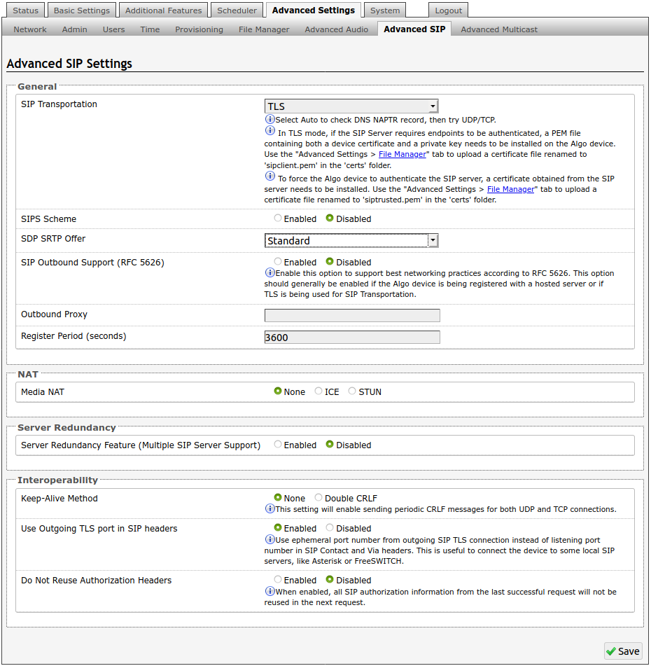
SIP signalling is secured by setting SIP Transportation to TLS (under the Advanced Settings → Advanced SIP tab). Setting it to TLS ensures that the SIP traffic will be encrypted. The SIP signalling is responsible for establishing the call (the control signals to start and end the call with the other party), but it does not contain the audio.
For the audio (voice) path, use the setting SDP SRTP Offer. Setting this to Optional, means the SIP calls RTP audio data will be encrypted (using SRTP) if the other party also supports audio encryption. If the other party does not support SRTP, then the call will still proceed, but with unencrypted audio. To make audio encryption mandatory for all calls, set SDP SRTP Offer to Standard. In this case, if the other party does not support audio encryption, then the call attempt will be rejected.
Note
For a SIP server to validate the Algo device, an additional certificate has to be manually installed on the 8410/8420. To add this user certificate file use a ‘.pem’ filetype extension and have the file named ‘sipclient’.
This is done by manually adding a file named ‘sipclient.pem’, which contains a device certificate and private key, to the ‘certs’ folder (under the ‘Advanced Settings’ tab File Manager’). In the future, ‘.crt’, ‘.cer’, and ‘.der’ certificate extensions will also be supported and you will not be restricted to naming the file ‘sipclient.pem’.
Web Interface
Status
Device Status
Web Interface Login
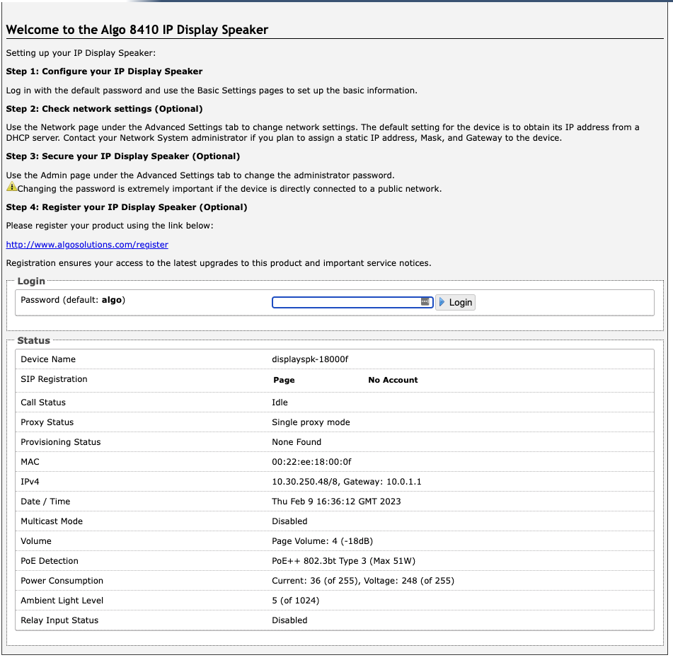
The web interface requires a password to login to see the device settings. The default password is algo. This password can be changed in the Admin tab after logging in the first time.
Note
Web Interface is accessed by entering 8410/8420 IP Address into the web browser.
Status
The Status page of the device will be available before and after logging on. This section can be used to check the status of the 8410/8420 for the following:
SIP Registration
Call Status
Proxy Status
Provisioning Status
MAC
IPv4
Date/Time
Multicast Mode
Volume
PoE Detection
Relay Input Status
Note
Your content goes hereFor security purposes, the Status page can be hidden when logged out through the settings under the Advanced Settings →Admin tab.
These options may change depending on how the device is configured.
Basic Settings
SIP
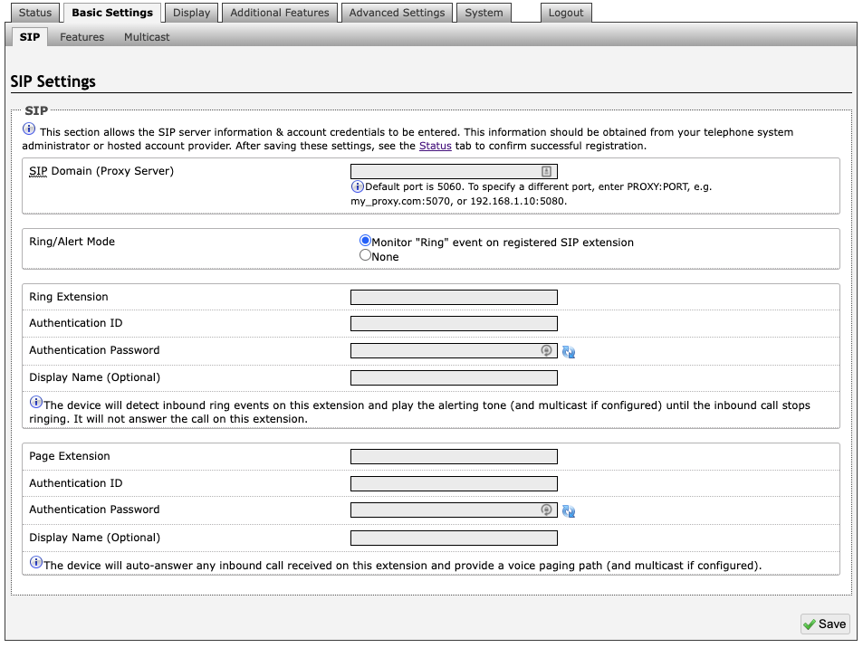
The SIP tab allows for the SIP server information and account credentials to be entered. This information can be obtained from your telephone system administrator or hosted account provider. After entering the information and saving the settings, go to the Status tab to confirm the registration was successful.
Note
Anytime changes are made to settings in the web interface the ‘Save’ button must be clicked to save the changes.
SIP Domain (Proxy Server)
The IP address (e.g., 192.168.1.111) or domain name (e.g., myserver.com) of the SIP Server.
Ring / Alert Mode
This is the option for adding a second SIP extension for a Ring event. If activated (“Monitor” is selected), the screen expands to show blocks for SIP extension parameters for a Ring/Alert Extension to be entered.
The device will detect inbound ring events on this extension and play the alerting tone (and multicast if configured) until the inbound call stops ringing. It will not answer the call on this extension.
Ring Extension
This is the SIP extension for the Ring parameter of the 8410/8420.
Page Extension
This is the SIP extension for the Page parameter of the 8410/8420. The device will auto-answer any inbound call received on this extension and provide a voice paging path (and multicast if configured).
Authentication ID
Also referred to as Username for some SIP servers. This, in some cases, may be the same as the Ring and/or Page extension. The authentication is a name you choose to represent the page extension.
Authentication Password
This is the SIP password provided by the system administrator for the registered SIP account. Up to eight (8) characters can be implemented. The password can be used to authenticate SIP users.
Display Name
The Display Name is shown on a receiving phone to which a SIP call is made. For the display name to be shown, the PBX and phone(s) need to be configured to display this message as the Caller ID.
Features
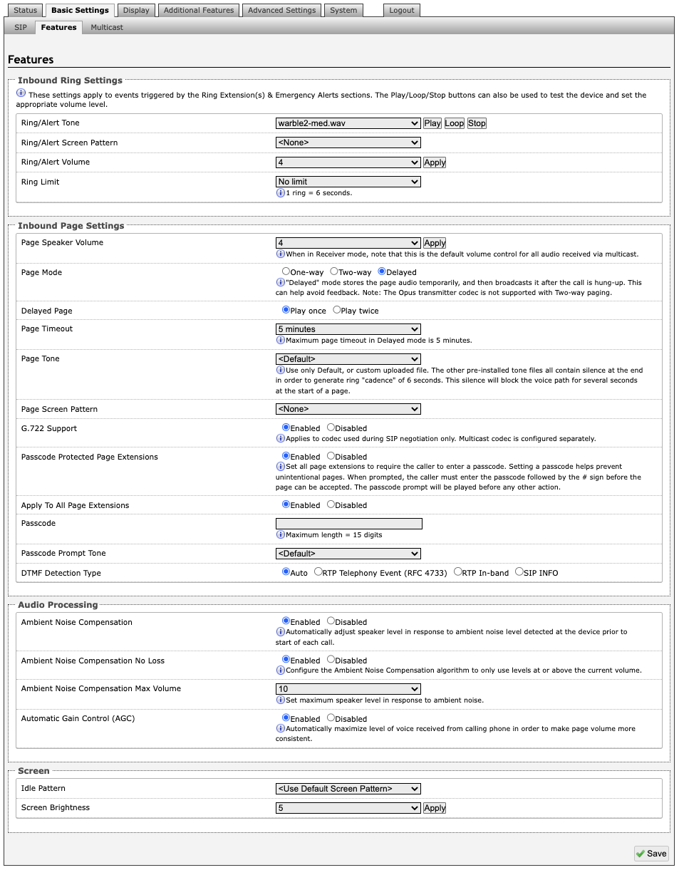
Inbound Ring Settings
Ring settings apply to events triggered by Ring Extensions and Emergency Alerts.
Ring/Alert Tone
Select an audio file to play when a ring event is detected on the SIP Ring Extension. The audio file may be played immediately to an associated speaker from the web interface for test purposes using the Play, Loop, and Stop buttons. During multicast, the device will broadcast an audio stream using the Senders selected ring tone.
Note
This is the “Default” tone that will be played if selected for Multicast, Additional Ring Extension settings.
Ring/Alert Screen Pattern
Select a screen pattern to display on the LCD screen on inbound ring events. Screen patterns are configured under Display → Screens.
Ring/Alert Volume
Set the speaker volume for a SIP Ring event. This setting is an amplifier gain control, and the output level will depend on the levels recorded into the source audio file played from memory. This setting is only used for local tones, and not when receiving multicast (see Page Speaker Volume below).
Ring Limit
Typically set to no limit, this feature can be used to set a limit on how long the speaker will ring before timing out. A new ring event is required before the speaker will play the audio file again.
Inbound Page Settings
Page Speaker Volume
This is the Page Speaker Volume control for SIP or multicast paging. This is an amplifier gain control and the output level will depend on streaming level. This setting will apply to all inbound multicast streams (for Receiver mode only), regardless of content.
Page Mode
A call to the SIP page extension can be one-way, two-way (using an external microphone), or delayed. In delay mode, the speaker will store the page into memory and then play after disconnecting.
Delayed Page
Delayed Page allows for a user to record a message before it is played over the speakers. To cancel a page while in delay mode, press “*” to while the recording state is in process to prevent it from being sent after hanging up.
Page Timeout
Page Timeout is the maximum duration for a page. The call will be terminated when the timeout occurs whether anyone is speaking or not. This is useful for situations when someone accidentally forgets to hang up, preventing the paging system from getting stuck in the active state. A time limit may be set for an active page.
Page Tone
Select a pre-announce tone for paging. This tone will play to announce a Page is starting. Use only the Default or custom uploaded files. Other pre-installed tone files contain silence at the end to generate ring "cadence" of 6 seconds. This silence will block the voice path for several seconds at the start of a page. The “Default” tone will play the page-notif.wav file.
Note
The “Default Page Tone”, in Advanced Multicast, will play the tone set here.
Page Screen Pattern
Select a screen pattern to display on the LCD screen on inbound page events. Screen patterns are configured under Display → Screens.
G.722 Support
G.722 enables wideband audio for optimum speech intelligibility. Enable or disable the G.722 codec.
Passcode Protected Page Extensions
When enabled, the caller must enter the passcode followed by the # sign before the page can be accepted. Setting a passcode helps prevent unintentional pages. Passcodes can be up to 15 digits and must be numbers only.
Apply to All Page Extensions
Choose to apply a passcode to all page extensions.
Passcode
Only visible when Passcode Protected Page Extensions is set to Enabled. Enter the desired numerical passcode (maximum length of 15 digits).
Passcode Prompt Tone
Only visible when Passcode Protected Page Extensions is set to Enabled. Select the tone to be played to notify the user to enter the passcode before paging.
DTMF Detection Type
Select the preferred dual-tone multi-frequency (DTMF) detection method. DTMF is a technology used with touch tone phones, best known to users as the sound made when pressing a number key. In the 8410/8420, this is used for multi-zone selection, passcode, etc.
Audio Processing
Ambient Noise Compensation
Ambient Noise compensation will allow the speaker level to adjust automatically in response to ambient noise levels detected at the device prior to the start of each call.
Ambient Noise Compensation No Loss
Configure the Ambient Noise Compensation algorithm to only use levels at or above the current volume. The current volume is the minimum speaker volume when this setting is enabled.
Ambient Noise Compensation Max Volume
Based on ambient noise levels, a maximum volume can be set for the speaker.
Automatic Gain Control (AGC)
AGC normalizes the audio level. This ensures the audio level heard near the speaker is always at a consistent level, independent of the phone that is used to answer the call.
Screen
Idle Pattern
Select a pattern to be displayed on the screen for when the 8410/8420 is idle. Patterns can include up to several screen displays and can vary to include a single image, a notification template, a clock display, and other configurations.
Screen Brightness
The screen brightness level can be adjusted according to the placement of the screen within a building to optimize visibility of content. Select a brightness level for the display screen on the 8410/8420.
Multicast
Multicast IP Addresses
Each 8410/8420 has its own IP address and shares a common multicast IP and port number (multicast zone) for multicast packets. The Sender transmits to a configurable multicast zone, and the Receiver units listen to all the multicast zones assigned to them.
The network switches and router see the packet and deliver it to all the members of the group. The multicast IP and port number must be the same on all the Transmitter and Receiver units of one group. The user may define multiple zones by picking different multicast IP addresses and/or port numbers.
Multicast IP addresses range: 224.0.0.0/4 (from 224.0.0.0 to 239.255.255.255)
Port numbers range: 1 to 65535
By default, the 8410/8420 is set to use the multicast IP address 224.0.2.60 and the port numbers 50000-50008
Make sure that the multicast IP address and port number do not conflict with other services and devices on the same network.
Multicast Page Zones
The 8410/8420 supports nine basic multicast zones. These zones are defined by the multicast IP addresses.
Somewhat arbitrarily, these zones are defined below but may be used in other ways. The important consideration is that there is a priority hierarchy – streaming activity on a zone higher on the list, will be treated as a higher priority than a zone lower down on the list – with music being the lowest priority.
Priority
All Call
Zone 1
Zone 2
Zone 3
Zone 4
Zone 5
Zone 6
Music
“Expanded” zones can also be enabled, in Basic Settings → Multicast, allowing up to 50 zones in total. These have the same behaviors as the basic zones but are hidden by default to simplify the interface.
Multicast (Transmitter/Sender Settings)
Note
See (Advanced Settings → Advanced Multicast) section for more information on populated IP values.
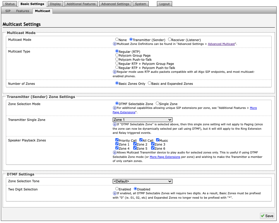
Multicast Mode
Multicast Mode (Transmitter/Sender Selected)
If Transmitter mode is enabled the 8410/8420 will broadcast an IP stream when activated in addition to playing the audio. (Note that the 8410/8420 cannot be both a multicast Transmitter and Receiver simultaneously).
Multicast Type
The 8410/8420 may broadcast multicast paging, compatible with Polycom “on premise group paging” protocol and most multicast-enabled phones that use RTP audio packets.
Select Regular if solely multicasting to Algo SIP endpoints and/or multicast-enabled phones.
To multicast page announcements solely to Polycom phones, select Polycom Group Page or Push-to-Talk. Then, configure the 8410/8420 with the Polycom Zone (IP Address and Port) and Polycom Default Channel.
Note
Always ensure that the multicast settings on all Receiver devices match those of the Transmitter
Select Regular RTP + Polycom Group Page/Push-to-Talk to multicast page audio to both Polycom phones, Algo SIP endpoints, and multicast-enabled phones.
Number of Zones
Select Basic Zones Only if configuring nine or fewer multicast zones (shown beside Speaker Playback Zones) or select Basic and Expanded Zones to configure up to 50 zones. The expanded zones have the same behavior as the basic Receiver zones but are hidden by default to simplify the interface.
Transmitter (Sender) Zone Settings
Polycom Group Selection Mode
Single Zone always broadcasts on one pre-configured Polycom Group. In DTMF Selectable Zone mode, the group is determined by the DTMF selection between 1 – 50.
Zone Selection Mode
“Single Zone” mode always broadcasts on one IP address.
Note
Multiple SIP extensions can be registered on the Transmitter device. Each extension is mapped to a unique zone, allowing zones to be called directly (e.g., from speed-dial keys). See Additional Features → More Page Extensions.
DTMF Selectable Zone mode, offers dynamic zone selection and requires only the Transmitter device to have a registered SIP Extension. The zone definitions can be found in the Advanced Settings → Advanced Multicast tab.
In DTMF Selectable Mode, to page, dial the SIP extension of the Transmitter device: ####, then dial the desired DTMF page zone (e.g., 1, 2, etc.) on the keypad when prompted.
Press DTMF Extension 9 for Priority Call
Press DTMF Extension 0 (or 8) for All Call
Press DTMF Extension 1 for Zone 1
Press DTMF Extension *10 for Zone 10
Press DTMF Extension *11 for Zone 11
Note
DTMF codes for zones 10 and higher start with an “*”
All DTMF codes and respective zones are available in Advanced Settings → Advanced Multicast.
Zone Selection Tone
Only visible when “Zone Selection Mode” is set to DTMF Selectable Zone. The tone played over the phone to prompt the user to select a zone to multicast to.
Transmitter Single Zone
The zone that multicast stream will be sent to by default. If DTMF Selectable Zone is chosen above, this setting will not apply to Paging, since the zone now must be dynamically selected per call via DTMF. However, the specified Transmitter Single Zone setting is still used for any multicast events triggered by the Ring, analog input, or the relay input.
Note
The Transmitter Single Zone is the default zone used for any multicast actions unless an option is created for a custom zone with specific parameters.
Speaker Playback Zones
The Speaker Playback Zones allows the Transmitter device to play audio for selected zones only. This is useful if using the DTMF Selectable Zone mode (or More Page Extensions per zone) with the intention of making the Transmitter unit a member of only certain zones. In this case, the Transmitter does not participate in the Zone, but it transmits certain traffic.
Expanded Speaker Playback Zones
Up to 50 zones can be shown and are only visible when Basic and Expanded Zones is selected.
DTMF Settings
Zone Selection Tone
This is the prompt to select a zone. This may be used as an interactive voice response (IVR) menu by uploading a custom audio file through System → File Manager in the Tones folder. Each zone may use a different tone. This can be configured in Advanced Settings → Advanced Multicast.
Two Digit Selection
When enabled, all DTMF Selectable Zones will require two digits. As a result, Basic Zones must be prefixed with 0 and Expanded Zones will no longer need to be prefixed with *.
Multicast (Receiver Settings)
Multicast Mode
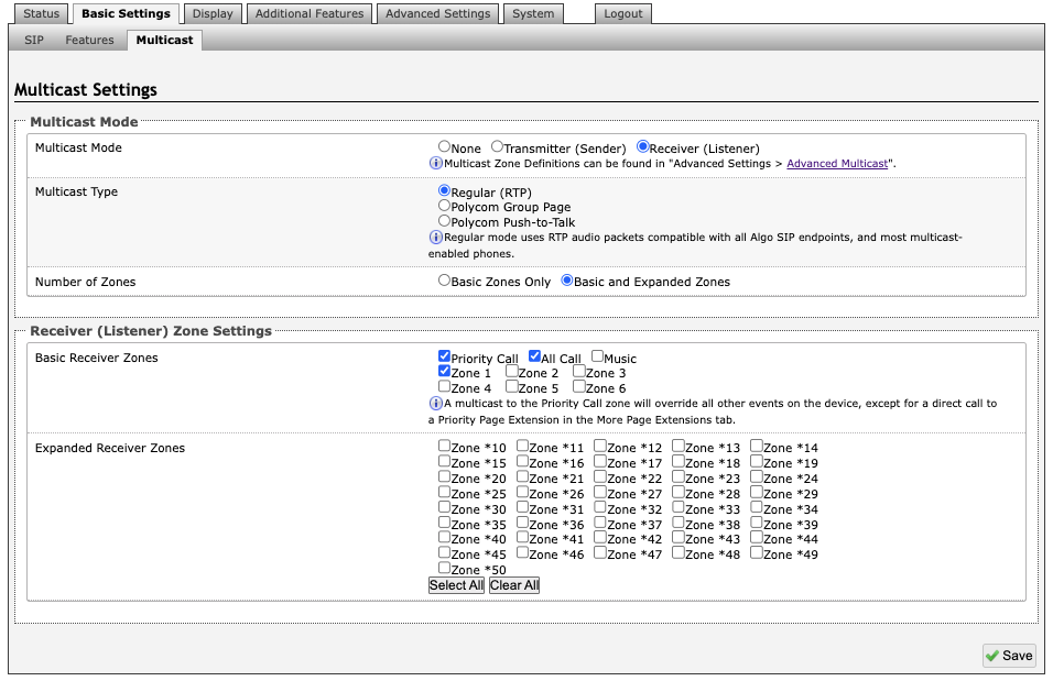
Multicast Mode (Receiver Selected)
If Receiver mode is enabled the 8410/8420 will activate when receiving a multicast message. It will mimic the audio stream but use local volume settings (Page Speaker Volume in Basic Settings → Features).
Multicast Type - Regular
Select “Regular” if receiving multicast from other Algo SIP endpoint(s) and/or multicast- enabled phone(s) that use RTP audio packets.
Number of Zones
Select basic zones if configuring nine or fewer multicast zones or expanded to configure up to 50 zones. The expanded zones have the same behaviour as the basic Receiver zones but are hidden by default to simplify the interface.
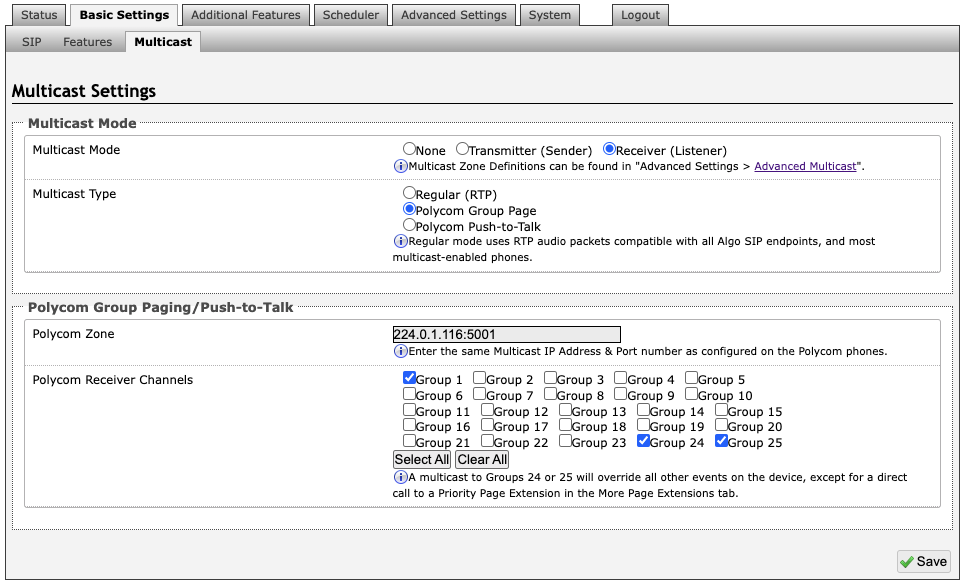
The 8410/8420 may receive multicast paging compatible with Polycom “on premise group paging” protocol.
To configure the 8410/8420 as a Receiver to play Polycom page announcements:
Select Group Page or Push-to-Talk.
Enter the Polycom Zone (IP Address and Port) that matches the configuration of the Polycom phones and Channels.
The Default Channel is the target group in a Polycom paging environment.
The Polycom phone used as page audio source for the 8410/8420 must be configured to use either the G.711 or G.722 audio codec. The Polycom phone(s) must also be configured with the “Compatibility” setting (“ptt.compatibilityMode”) disabled in order for this codec setting to be applied.
If using a Polycom phone as the Multicast Transmitter, a tone may be set for any of the 25 Polycom Groups configured on the Algo device. If an Algo device is used as a Multicast Transmitter, a tone does not have to be set as the Algo Transmitter will provide its own tone. Polycom Group Tones can be set in Advanced Settings → Advanced Multicast.
Receiver (Listener) Zone Settings
Basic Receiver Zones
Select one or more multicast zones for the 8410/8420 to subscribe to.
Note
Multicast zone priority is based on the zone definition list order (from top to bottom) in Advanced Settings → Advanced Multicast.
Expanded Receiver Zones
Up to 50 zones can be shown, however, they are only visible when Basic and Expanded Zones is selected.
Display
The 8410/8420 allows flexible visual communication via the display. The displays can be configured to deliver a variety of notification messages, such as clocks, scrolling texts, slideshow-style images, flashing announcements or general messages. The power of the device comes down to optimizing the screens for your application. In the next section, we will go through how to configure different slide options.
Within the Display tab, there are three (3) tab options: Screens, Slides, Data. The Screens tab allows you to select a slide to display on the device, the Slides tab allows you to create new or existing slides to use, the Data tab allows you to download images from the Algo server to use in the slides.
Screens
In this tab, you can dictate what will be displayed on the screen. Slides are created in the Slides tab. The Screens tab allows you to assign content to display. You can choose the screens to display to SIP or multicast events as well as the default display for when an event is not in progress.
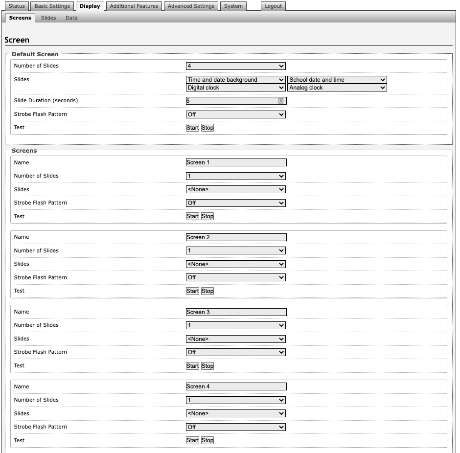
Default Screen
Number of Slides
Select the number of slides to cycle through on the display screen.
Slides
In order from left to right, top to bottom, select each slide to display. Slides can be created under Display → Slides.
Slide Duration (seconds)
Choose how long each slide will show on the display screen in seconds.
Strobe Flash Pattern
Choose a flash pattern for the LEDs. If enabled, this will be displayed while the default screen is on.
Strobe Brightness
When strobe flash pattern is selected, the option for the strobe brightness can be selected.
Strobe Color
Select a color to display.
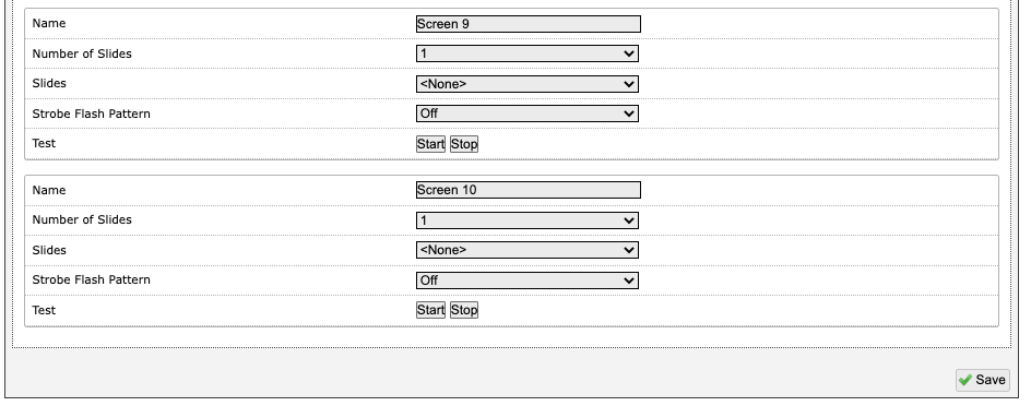
Screens
Name
Choose a name that coordinates with the intention of your screens usage.
Number of Slides
Select the number of slides you wish to display for the screen display.
Slides
In order from left to right, top to bottom, select each slide to display. Slides can be created under Display → Slides.
Strobe Flash Pattern
Choose a flash pattern for the LEDs. If enabled, this will be displayed while the default screen is on.
Slides
Slides can be created or edited in this tab based on event. Preconfigured templates are provided to customize content.
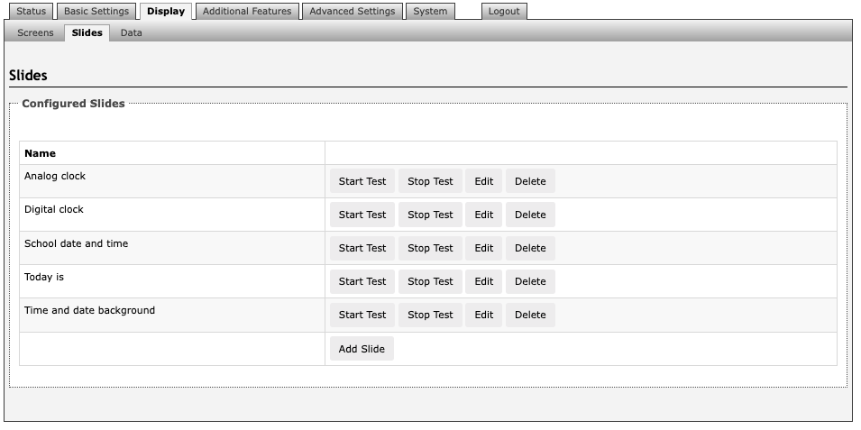
Edit preconfigured slides or add new slides to customize your experience using the 8410/8420 with your companys branding.
Add Slides
Press Add Slide to create a new slide based on preconfigured templates. Slide types may include an analog or digital clock display, a new template for notifications or alerts.
Clock
The digital clock setting allows you to change background and font colors.
Template
Choose a template for your Slide based on the purpose. This can include emergency alerts, notifications, weather warnings, or event updates.
Data
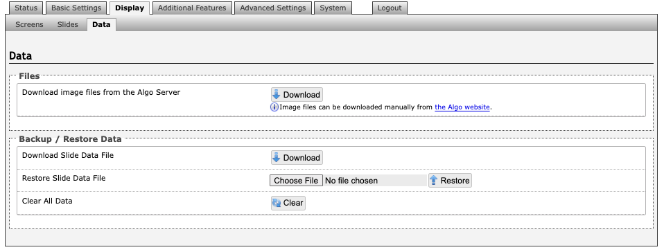
Download Image Files from Algo Server
Downloads the factory images from the Algo Server (internet connection is required).
Download Slide Data File
Allows an image to be downloaded and stored for backup purposes. Note that this backup is independent from the rest of the configuration backup on the device.
Restore Slide Data File
Upload and restore a saved slide data file.
Clear All Data
This clears all the slide data, including saved slides.
Additional Features
Input/Output
The Input tab allows external accessories to be connected to the 8410/8420. This is a dry contact input which can be configured as normally open or normally closed mode. Algo offers accessories, such as the 1202, 1203, 1204, and 2507. Third-party accessories/systems may also be used provided they have a dry contact output.
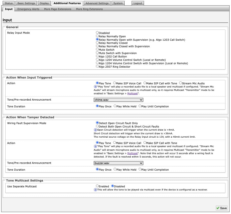
General
Relay Input Mode
The input relay to the 8410/8420 can be activated by any normally open or normally closed switch. Algo offers the 1202 Call Button, the 1203 Call Switch, or 1204 Volume Control Switch. Via supervision settings, notification actions can also be triggered if the input switch is disconnected.
1203 Call Switch The 1203 Call Switch is a simple contact closure switch with an illuminated button and supervision capabilities. When used in conjunction with the 8410, the 1203 can prompt a single action with one-touch, or a continuous action if the button is held. |
|

Mute Switch
Apply an external switch (short-circuit) across the Relay Input terminals in order to mute the 8410/8420. This allows a temporary "disable" switch to control the device if desired, for example in a boardroom to block paging during important meetings.
Leave the Relay Input terminals open (no-connect) for regular full-volume operation when in this mode.
Multicast Override
Allow selected multicast zones to override the Mute Switch settings for the selected zones.

While the 8410/8420 can be configured to play the audio file only once, it can also be enabled to play it continuously with just a press of the 1202 Call Button. The action can then be stopped via the smaller oval cancel button located below the main call button on the 1202 Call Button.
1204 Volume Control The 1204 Volume Control Switch is a simple two terminal potentiometer that will allow attenuation below the maximum volume level (configured under Basic Settings → Features). |
|
.png)
Mute On Lowest Setting
Enabling Mute On Lowest Setting allows audio to be completely muted when volume control switch is turned all the way down.
Wire Length
This allows you to calibrate impedance for 24 AWG.
Multicast Override
Multicast Override allows selected multicast zones to override the 1204 Volume Control settings for the selected zones.
Remote Volume Settings
Configure the device to subscribe to remote 1204 volume input or to notify remote devices of 1204 volume input.
Note
RESTful API must be enabled in the Advanced Settings → Admin tab.
Notify (Local 1204) → remote device RESTful API password
Subscribe (Remote 1204)
IP address
Remote device RESTful API password
Action When Input Triggered
Action
Play Tone
When the 8410/8420 input is triggered, a tone or a pre-recorded audio file will play over the speaker or multicast if enabled. This function can be used to request support/assistance in service or retail environments, notify about an emergency at a specific location in medical or educational facilities, or sound an alarm during an intrusion.
Action When Input Triggered:
Tone/Pre-recorded Announcement
Tone Duration
Make SIP Voice Call
When the 8410/8420 input is triggered, a voice path will open for an intercom-like call via an external microphone to a pre-configured phone extension. This option can be used when a call needs to be made from a public place where a phone would not be practical to use.
Action When Input Triggered:
Extension to Dial
Call Mode
Allow 2nd Button Press
Outbound SIP Call Settings:
Outbound Ring Limit
Ringback Tone
Maximum Call Duration
Make SIP Call with Tone
When the 8410/8420 input is triggered, a private call can be generated to a pre-configured phone extension with a pre-recorded message. For instance, a call to a supervisors phone notifying about an emergency or intrusion at some location.
Action When Input Triggered:
Extension to Dial
Allow 2nd Button Press
Tone/Pre-recorded Announcement
Interval Between Tones (seconds)
Maximum Tone Duration
Outbound SIP Call Settings:
Outbound Ring Limit
Allow 2nd Button Press
If enabled, the 2nd button press will either simply End Call or End and Restart Call. Therefore, if an input is triggered for the second time the SIP call will either simply be terminated or terminated and immediately called again.
Action When Tamper Detected (Supervision)
In addition to the main events, the device can be configured with supervision to also execute one of the above three actions (Play Tone, Make Two-Way SIP Voice Call, Make SIP Call with Tone) in case the device goes offline due to wiring failure or after being tampered with. For example, a tone could sound over the speaker(s), or a private pre-recorded message could be sent to a specified phone extension. The supervision configuration options will appear once a relay option with supervision is selected. See the Electrical Specification section for details on supervision detection circuit.
Wiring Fault Supervision Mode
Short circuit detection will be triggered when the current draw is <4 mA. Short circuit detection will trigger when the current draw is >36 mA. The nominal source voltage on the Relay Input circuit is 13 V, with 40 mA current limit.
Action
“Play Tone” will play a recorded audio file to a local speaker and multicast if configured. “Stream Mic Audio” will stream microphone audio to multicast only, so it requires multicast “Transmitter” mode to be enabled in Basic Settings → Multicast.
Note
This action will occur 5 seconds after a wiring fault is detected. If the fault is resolved within 5 seconds, this action will not occur.
Play Tone
Make SIP Voice Call
Make SIP Call with Tone
Tone/Pre-recorded Announcement (Action – Play Tone / Make SIP call with Tone)
Select a recording or tone to use. Custom audio files may be used and uploaded though System → File Manager.
Extension to Dial (Action – Make SIP Voice Call)
SIP account required in Page Extension fields in order to make a call. Can be configured if Make SIP Voice Call or Make SIP Call with Tone actions are enabled under Call Button Settings.
Interval Between Tones (Action –Make SIP call with Tone)
Specify the time delay (seconds) between tones. Can be configured if Play Tone or Make SIP Call with Tone actions are enabled under Call Button Settings.
Maximum Tone Duration (Action – Play Tone / Make SIP call with Tone)
Select the maximum tone duration. The tone will be terminated once the maximum time is reached. Can be configured if Play Tone or Make SIP Call with Tone actions are enabled.
Tone Multicast Settings
Use Separate Multicast
This allows the tone to be played via multicast even if the 8410/8420 is configured as a receiver. See additional options when enabled.
Multicast Mode
IP Address
Port
Outbound SIP Call Settings
Outbound Ring Limit
Typically set to ensure that a call will not reach voicemail. This feature, under Outbound SIP Call Settings, can be used to set a limit on how long the speaker will ring before timing out.
Ringback Tone
If enabled, under Outbound SIP Call Settings, a ringback tone will play over the speaker during an outbound SIP call, while waiting for the far-end party to answer.
Emergency Alerts
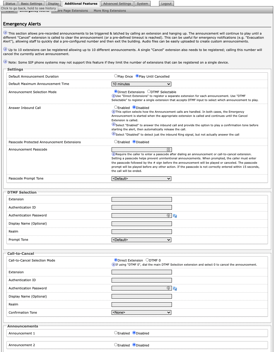
Emergency Alerts allow for an announcement to be triggered and latched by calling a pre-configured Emergency extension and hanging up. Emergency Alerts are useful for emergency notifications (e.g., evacuation, lock down, medical emergency, etc.), allowing staff to quickly dial a pre-configured number under such circumstances.
Settings
Default Announcement Duration
The announcement can be chosen to play once or to play until cancel. Play Once mode will play a single cycle of the chosen tone file, despite of its duration. If Play Until Cancelled is selected, the announcement will continue to play until the "Call-to-Cancel" extension is called to clear the announcement (or a defined timeout is reached).
Default Maximum Announcement Time
This represents the duration for how long the announcement plays for.
Announcement Selection Mode
Use Direct Extensions to register a separate extension for each announcement. Use DTMF Selectable to register a single extension that accepts DTMF input to select which announcement to play.
Answer Inbound Call
This option selects how the Announcement calls are handled. In both cases, the Emergency Announcement is started when the appropriate extension is called and continues until the Cancel Extension is called. Select Enabled to answer the inbound call and provide the option to play a confirmation tone before starting the alert, then automatically release the call. Select Disabled to detect just the inbound Ring signal, but not actually answer the call.
If the Answer Inbound Call option is Enabled the call is auto answered and a configurable confirmation tone is played before starting the alert. If Disabled, the alert is triggered just by the inbound ring, without answering the call. (In both instances, the announcement will play until the time limit is reached or the Cancel Extension is called). The auto-answering option can be useful when the caller cannot hear announcement from their location. However, in instances where the call might go to a group/multiple extension(s) (including this device), the auto-answer may intercept that call and prevent it from ringing on other devices.
Passcode Protected Announcement Extensions
When enabled, this setting requires the caller to enter a passcode after dialing an announcement or call-to-cancel extension. Setting a passcode helps prevent unintentional announcements.
Announcement Passcode
When prompted, the caller must enter the passcode followed by the # sign before the announcement will be played or canceled. The passcode prompt will be played before any other action. If the passcode is not correctly entered within 15 seconds, the call will be ended.
Passcode Prompt Tone
Select a tone to play when the passcode is ready to be entered.
DTMF Selection
Extension
This is the SIP extension for the DTMF Selection parameter of the 8410/8420. The device will auto-answer any inbound call received on this extension and provide a voice paging path (and multicast if configured).
Authentication ID
The Authentication ID may also be called Username for some SIP servers and in some cases may be the same as the Ring and/or Page extension.
Authentication Password
This is the SIP password provided by the system administrator for the SIP account.
Display Name (Optional)
Enter a Display Name that will be sent when the SIP call is made. The PBX and phone(s) will have to be configured to display this message as the Caller ID.
Prompt Tone
Select a tone to play when the passcode is ready to be entered.
Call-to-Cancel
Call-to-Cancel Selection Mode
If using “DTMF 0”, dial the main DTMF Selection extension and select 0 to cancel the announcement.
Extension
This is the SIP extension for the Call-to-Cancel Selection parameter of the 8410. The device will auto-answer any inbound call received on this extension and provide a voice paging path (and multicast if configured).
Authentication ID
The Authentication ID may also be called Username for some SIP servers and in some cases may be the same as the Ring and/or Page extension.
Authentication Password
The SIP password is provided by the system administrator for the SIP account.
Display Name (Optional)
Enter a Display Name that will be sent when the SIP call is made. The PBX and phone(s) will have to be configured to display this message as the Caller ID.
Prompt Tone
Select a tone to play when the passcode is ready to be entered.
Announcements
Announcement 1
To configure an emergency alert extension, select Enable beside the target announcement and enter the Extension, Authentication ID, and Authentication password.
Up to 10 extensions can be registered allowing up to 10 different announcements. Audio files can also be easily uploaded to create custom announcements. Only one Call-to-Cancel extension is needed, despite the number of the alert extensions.
Note
Some SIP phone systems may not support this feature if they limit the number of extensions that can be registered on a single device.
Announcement Duration
Choose how long to allow for the announcement duration. An announcement can:
Play Once
Play Until Cancelled
Default
Extension
This is the SIP extension for the Call-to-Cancel Selection parameter of the 8410. The device will auto-answer any inbound call received on this extension and provide a voice paging path (and multicast if configured).
Authentication ID
The Authentication ID may also be called Username for some SIP servers and in some cases may be the same as the Ring and/or Page extension.
Authentication Password
The SIP password is provided by the system administrator for the SIP account.
Display Name (Optional)
Enter a Display Name that will be sent when the SIP call is made. The PBX and phone(s) will have to be configured to display this message as the Caller ID.
More Page Extensions
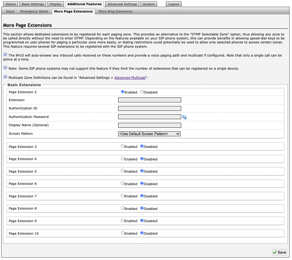
Additional SIP extensions can be registered for each multicast zone that will be used. This allows the advantage of dialing directly to a zone without needing to enter DTMF Codes (e.g., speed-dial keys can be used), but this may require additional SIP licenses depending on the SIP provider.
To configure additional page extensions (up to 50), select Enable beside the target extension and enter the Extension, Authentication ID, and Authentication password.
The 8410/8420 will auto-answer any inbound calls received on these numbers and provide a voice paging path and multicast if configured. Only a single call can be active at a time.
Note
Some SIP phone systems may not support this feature if they limit the number of extensions that can be registered on a single device.
More Ring Extensions
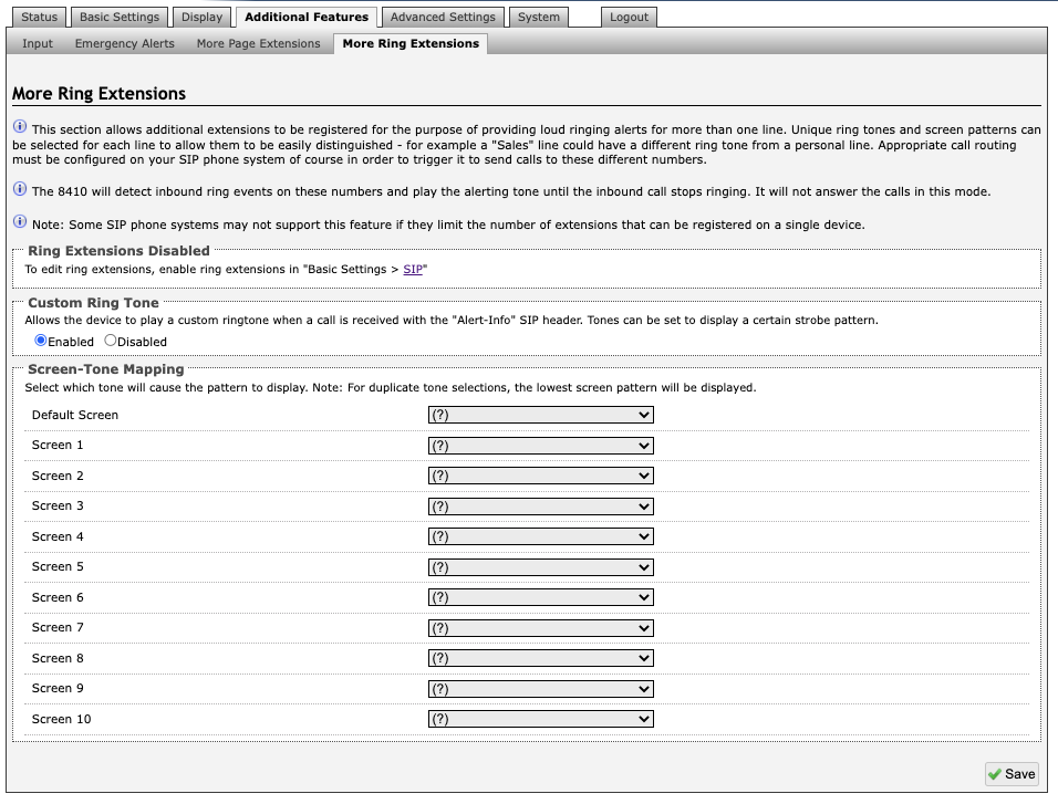
Up to 10 SIP Ring extensions can be registered. To configure additional ring extensions, select Enable beside the target extension and enter the Extension, Authentication ID, and Authentication Password. A unique Ring Tone and Multicast Zone can be assigned to each extension if desired.
Default Screen
Select a default screen to display during a ring.
Advanced Settings
Network
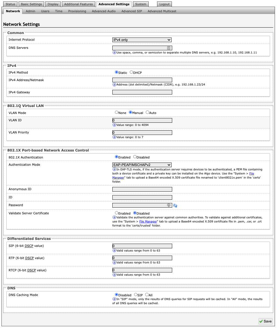
Common
Internet Protocol
DHCP is an IP standard designed to make the administration of IP addresses simpler. When selected, DHCP will automatically configure IP addresses for each 8410/8420 on the network. Alternatively, the 8410/8420 can be set to a static IP address.
DNS Servers
Add one or multiple DNS servers. Separate each server by a space, comma, or semicolon.
IPv4
IPv4 Method
The 8410/8420 can be set to a DHCP or a static IP address. When DHCP is selected, the DHCP will automatically configure IP addresses for each 8410/8420 on the network.
IPv4 Address/Netmask
Enter the static IP address and netmask (CIDR format) for the 8410/8420 (e.g., 192.168.1.23/24).
IPv4 Gateway
Enter the gateway address.
802.1Q Virtual LAN
VLAN Mode
Enables or Disables VLAN Tagging. VLAN Tagging is the networking standard that supports Virtual LANs (VLANs) on an Ethernet network. The standard defines a system of VLAN tagging for Ethernet frames and the accompanying procedures to be used by bridges and switches in handling such frames. The standard also provides provisions for a quality-of-service prioritization scheme commonly known as IEEE 802.1p and defines the Generic Attribute Registration Protocol.
VLAN ID
Specifies the VLAN to which the Ethernet frame belongs. A 12-bit field specifying the VLAN to which the Ethernet frame belongs. The hexadecimal values of 0x000 and 0xFFF are reserved. All other values may be used as VLAN identifiers, allowing up to 4094 VLANs. The reserved value 0x000 indicates that the frame does not belong to any VLAN; in this case, the 802.1Q tag specifies only a priority and is referred to as a priority tag. On bridges, VLAN 1 (the default VLAN ID) is often reserved for a management VLAN; this is vendor specific.
VLAN Priority
Sets the frame priority level. Otherwise known as Priority Code Point (PCP), VLAN Priority is a 3-bit field which refers to the IEEE 802.1p priority. It indicates the frame priority level. Values are from 0 (lowest) to 7 (highest).
802.1X Port-based Network Access Control
802.1x Authentication
Credentials to access LAN or WLAN that have 802.1X network access control (NAC) enabled. This information will be available from the IT Administrator.
Authentication Mode
Select the desired authentication mode.
Anonymous ID
If configured, the 8410/8420 will send the anonymous ID to the authenticator instead of the 802.1X client username.
ID
The ID should contain a string identifying the IEEE 802.1X authenticator originating the request.
Password
Enter the password.
Validate Server Certificate
Validate the authentication server against common authorities. To validate against additional certificates, go to the System → File Manger to upload a Base64 encoded X.509 certificate file in .pem, .cer, or .crt format to the certs/trusted folder.
Differentiated Services
This provides quality of service if the DSCP protocol is supported on your network. The Differentiated Services can be specified independently for SIP control packets versus RTP and RTCP audio packets.
SIP (6-bit DSCP value)
Enter the DSCP value for SIP packets.
RTP (6-bit DSCP value)
Enter the DSCP value for RTP packets.
RTCP (6-bit DSCP value)
Enter the DSCP value for RTCP packets.
DNS
DNS Caching Mode
In "SIP" mode, only the results of DNS queries for SIP requests will be cached. In "All" mode, the results of all DNS queries will be cached.
Admin
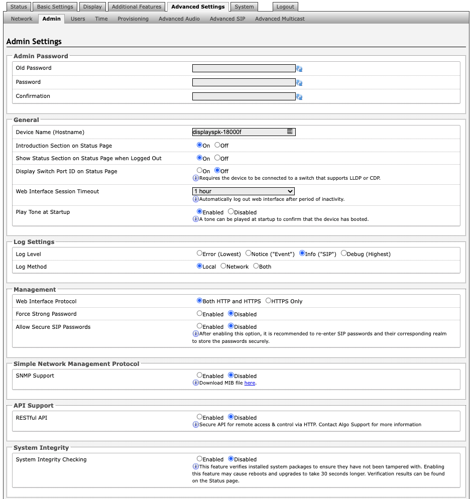
Admin Password
Old Password
Enter the old password.
Password
Password to log into the 8410/8420 web interface. You should change the default password algo to secure the device on the network. If you have forgotten your password, you will need to perform a reset using the Reset Button to restore the password (as well as all other settings) back to the original factory default conditions.
For additional password security see “Force Strong Password” below.
Confirmation
Re-enter network admin password.
General
Device Name (Hostname)
Name to identify the device in the Algo Network Device Locator Tool.
Introduction Section on Status Page
Allows the introduction text to be hidden from the login screen.
Show Status Section on Status Page when Logged Out
Use this option if you wish to block access to the status page when logged out. The settings and configurations, on the status page, will be hidden entirely unless youre logged in – this feature is useful when you want only trusted users to view possible sensitive device information.
Display Switch Port ID on Status Page
Enable this option to display the Switch Port ID. This option requires the 8410/8420 to be connected to a switch that supports LLDP or CDP.
Web Interface Session Timeout
Set the maximum period of inactivity after which the web interface will log out automatically.
Play Tone at Startup
A tone can be played at start up to confirm that the device has booted.
Log Settings
Log Level
The Log Level is to be used on the advice of Algo technical support only.
Log Method
Allows the 8410/8420 to write to external Syslog server if the option for external (or both) is selected.
Log Server
If Network or Both is selected this is the address of the Syslog server on the network.
Management
Web Interface Protocol
HTTPS is always enabled on the device. Use HTTPS Only mode to disable HTTP, then requests will be automatically redirected to HTTPS. Also note that since the device can have any address on the local network, no security certificate exists, and thus most browsers will provide a warning when using HTTPS.
Force Strong Password
When enabled, ensures that a secure password is provided for the devices web interface for additional protection. The password requirements are:
Must contain at least 10 characters
Must contain at least 1 uppercase character
Must contain at least 1 digit (0 – 9)
Must contain at least 1 special character
Allow Secure SIP Password
Allows SIP passwords to be stored in the configuration file in an encrypted format, to prevent viewing and recovery. Once enabled, the SIP Realm field should be entered and all the configured Authentication Password(s) must be re-entered in Basic Settings → SIP, and any other locations where SIP extensions have been configured, to save the encrypted password(s).
If the Realm is changed at a later time, all the passwords will also need to be re-entered again to save the passwords with the new encryption.
To obtain your SIP Realm information, contact your SIP Server administrator (or check the SIP log file for a registration attempt). The Realms may be the same or different for all the extensions used.
Simple Network Management Protocol
SNMP Support
Additional SNMP support is anticipated for future. The current setting of the 8410/8420 will respond to a simple status query for automated supervision. Contact Algo technical support for more information.
API Support
RESTful API
Secure API for remote access and control via HTTP.
System Integrity
System Integrity Checking
This feature verifies installed system packages to ensure they have not been tampered with by running Perform Check. Enabling this feature may cause reboots and upgrades to take 30 seconds longer. Verification results can be found on the Status tab.
Power over Ethernet
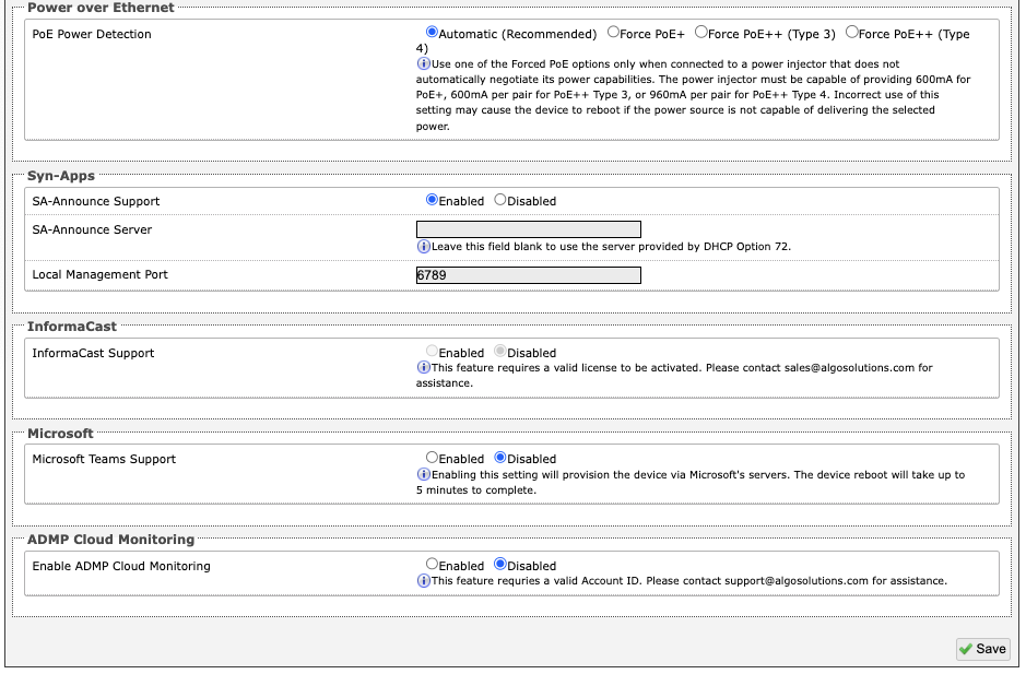
PoE Power Detection
Use one of the Forced PoE options only when connected to a power injector that does not automatically negotiate its power capabilities. The power injector must be capable of providing 600 mA for PoE+, 600 mA per pair for PoE++ Type 3, or 960 mA per pair for PoE++ Type 4. Incorrect use of this setting may cause the device to reboot if the power source is not capable of delivering the selected power.
Syn-Apps
SA-Announce Support
Syn-Apps SA-Announce paging application converts unicast streams to multicast and delivers them to the target endpoints. The feature can only be used on the 8410/8420 when Multicast Sender Mode is disabled (set to None) in the Basic Settings → Multicast tab.
SA-Announce Server
Enter the SA-Announce Server to use the Syn-Apps paging feature. To use the server provided by the DHCP Option 72, leave the field blank.
Local Management Port
Enter the local management port for the SA-Announce Server.
InformaCast
InformaCast Support
This feature requires a valid InformaCast license to be activated. Please contact sales@algosolutions.com for assistance.
Microsoft
Microsoft Teams Support
Enabling this setting will provision the device via Microsofts servers. The device reboot will take up to 5 minutes to complete.
ADMP Cloud Monitoring
Enable ADMP Cloud Monitoring
This feature requires a valid Account ID. Please contact sales@algosolutions.com for assistance.
Users
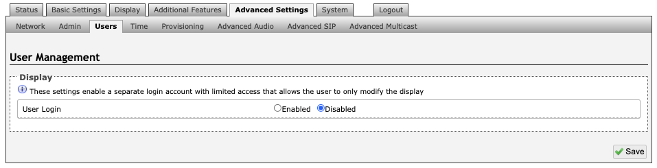
A separate login account with limited access can be set up. The user will only be able to modify the device scheduler.
Time
Network time is used for logging events into memory for troubleshooting.
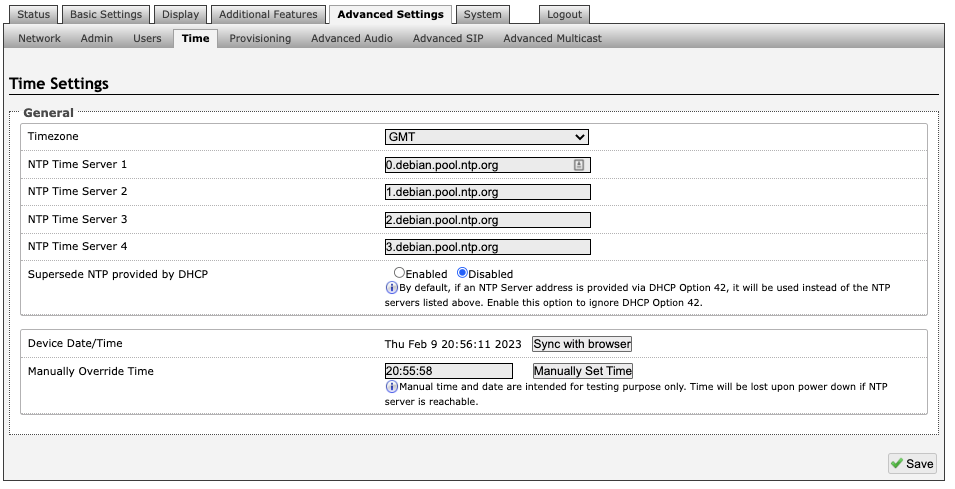
Timezone
Select a time zone to be used.
NTP Time Servers 1/2/3/4
The interface will attempt to use Timer Server 1 and work down the list if one or more of the time servers become unresponsive.
Supersede NTP provided by DHCP
When Use DHCP Option 42 is chosen, if an NTP Server address is provided via the DHCP Option 42, that NTP Server will be used instead of the four (4) mentioned above. Alternatively, Ignore DHCP Option 42 can be chosen to only use servers mentioned above.
Device Date/Time
This field shows the current time and date as set on the device. If testing the device on a lab network that may not have access to an external NTP server, the “Sync with browser” button can be used to temporarily set the time on the device.
Provisioning
Note
It is recommended that Provisioning Mode be set to Disabled if this feature is not in use. This will prevent unauthorized re-configuration of the device if DHCP is used.
Mode
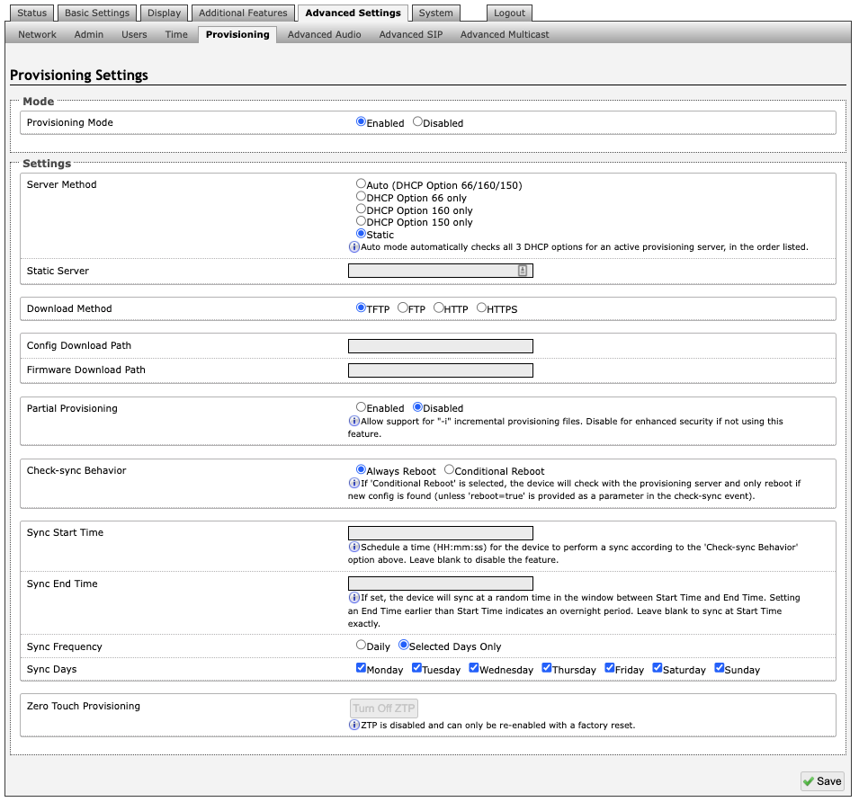
Provisioning Mode
Provisioning allows installers to pre-configure the 8410/8420 units prior to installation on a network. It is typically used for large deployments to save time and ensure consistent setups.
Settings
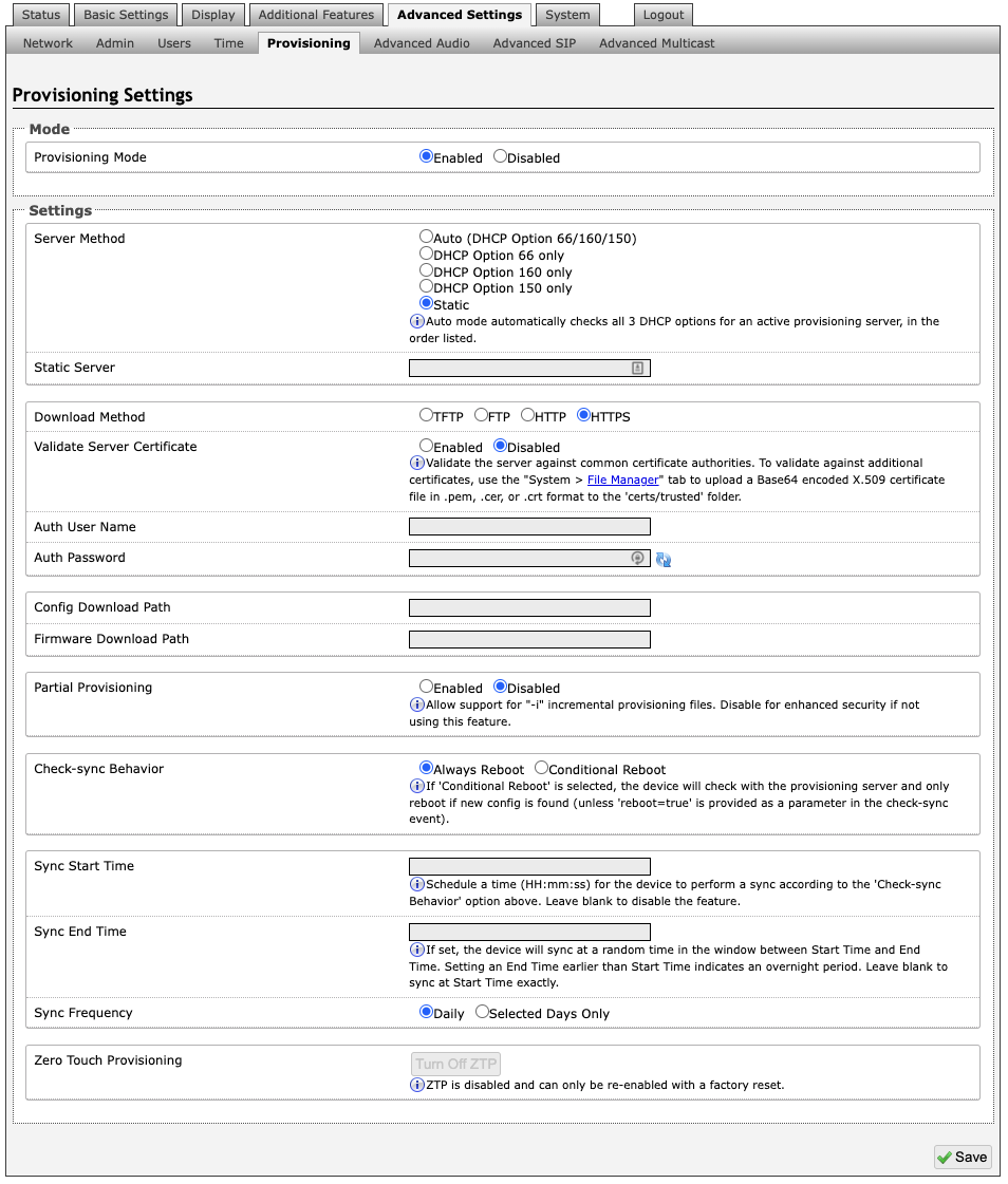
Server Method
The device can be provisioned via the Auto mode (where all three DHCP options (Option 66/160/150) will be automatically checked for an active provisioning server), just one of the three specified DHCP options, or a Static Server. In addition, there are four different ways to download provisioning files from a “Provisioning Server”: TFTP (Trivial File Transfer Protocol), FTP, HTTP, or HTTPS.
Static Server
Enter the server address or domain.
Download Method
The 8410/8420 configuration files can be automatically downloaded from a TFTP server using DHCP Option 66. This option code (when set) supplies a TFTP boot server address to the DHCP client to boot from.
Note
DHCP must be enabled if using DHCP Option 66/160/150, in order for Provisioning to work.
One of two files can be uploaded on the Provisioning Server (for access via TFTP, FTP, HTTP, or HTTPS):
Generic (for all Algo 8410/8420) algop8410.conf or algop8420.conf
Specific (for a specific MAC address) algom[MAC].conf
Both protocol and path are supported for Option 66, allowing for http://myserver.com/config-path to be used.
Config Download Path
Enter the path where the configuration file Is located within the provisioning server (e.g. algo/config/8410).
Firmware Download Path
Enter the path where the firmware file Is located within the provisioning server (e.g. algo/firmware/8410).
Partial Provisioning
Allow support for “-i” incremental provisioning files. Disable for enhanced security if not using this feature.
Check-sync Behavior
If Conditional Reboot is selected, the device will check with the provisioning server and only reboot if a new config is found (unless “reboot=true” is provided as a parameter in the check-sync event).
Sync Start Time
Schedule a time (hh:mm:ss) for the device to perform a sync according to the Check-sync Behavior option above. Leave blank to disable the feature.
Sync End Time
If set, the device will sync at a random time in the window between Start Time and End Time. Setting an End Time earlier than the Start Time indicates an overnight period. Leave blank to sync at Start Time exactly.
Sync Frequency
Choose the frequency for which this setting should occur. Select between daily or go to Sync Days to choose specific days of the week.
Sync Days
Select the days of the week to apply this setting for.
MD5 Checksum
In addition to the .conf file, an .md5 checksum file must also be uploaded to the Provisioning server (for TFTP mode only). This checksum file is used to verify that the .conf file is transferred correctly without error.
A tool such as can be found at the website address below and may be used to generate this file: http://www.fourmilab.ch/md5
The application doesn’t need an installation. To use the tool, simply unzip and run the application (md5) from a command prompt. The proper .md5 file will be generated in the same directory.
If using the above tool, be sure to use the “-l” parameter to generate lower-case letters.
Generating a generic configuration file
If using a generic configuration file, extensions and credentials have to be entered manually once the 8410/8420 has automatically downloaded the configuration file.
To see Algo’s SIP endpoint provisioning guide, visit: www.algosolutions.com/provision
Generating a Specific Configuration File
The specific configuration file will only be downloaded by the 8410/8420 with the MAC address specified in the configuration file name. Since all the necessary settings can be included in this file, the 8410/8420 will be ready to work immediately after the configuration file is downloaded. The MAC address of each 8410/8420 can be found on the back label of the unit.
To see Algo’s SIP endpoint provisioning guide, visit: www.algosolutions.com/provision
Advanced Audio
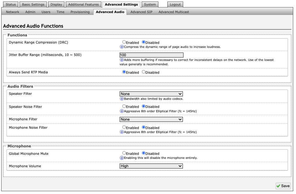
Functions
Dynamic Range Compression (DRC)
If enabled, compresses the dynamic range of page audio to increase loudness.
Dynamic Range Compression Gain
Higher compression gain increases distortion.
Jitter Buffer Range
The jitter buffer removes the jitter in arriving network packets by temporarily storing them. This process corrects the inconsistent delays on the network. It is recommended to use the lowest value.
Always Send RTP Media
If enabled, audio packets will be sent at all times, even during one-way paging mode. This option is needed in cases when the server expects to see audio packets at all times.
Audio Filters
Speaker Filter
Applies a high-pass filter to the speaker output. Used to reduce audio artifacts like humming or buzzing by filtering out unwanted frequencies.
Speaker Noise Filter
Enables heavy filtering below 145 Hz to reduce mains induced noise (fans).
Microphone Filter
Applies a high-pass filter to the microphone input. Used to reduce audio artifacts like humming or buzzing by filtering out unwanted frequencies.
Microphone Noise Filter
Enables heavy filtering below 145 Hz to reduce mains induced noise (fans).
Microphone
Global Microphone Mute
Enabling this will disable the microphone entirely.
Microphone Volume
Select a volume for the microphone.
Advanced SIP
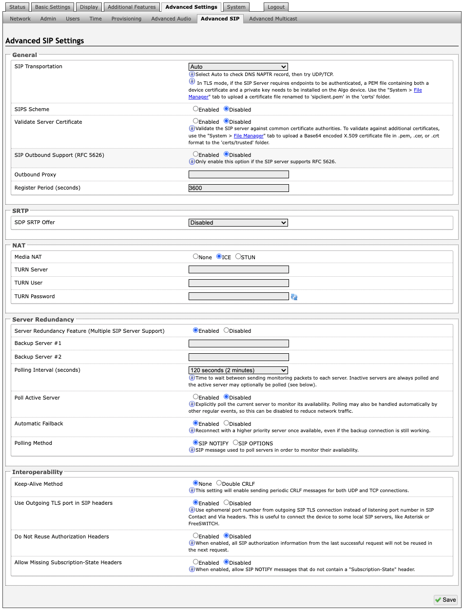
General
SIP Transportation
Which transport layer protocol to use for SIP messages. Setting SIP Transportation to TLS, ensures the encryption of SIP traffic.
SIPS Scheme
Only visible when SIP Transportation set to TLS. Enabling SIPS Scheme requires the SIP connection from endpoint to endpoint to be secure.
Validate Server Certificate
Validate the SIP server against common certificate authorities.
SIP Outbound Support (RFC 5626)
Enable this option to support best networking practices according to RFC 5626. This option should generally be enabled if the Algo device is being registered with a hosted server or if TLS is being used for SIP Transportation.
Outbound Proxy
IP address for outbound proxy. A proxy (server) stands between a private network and the internet.
Register Period (seconds)
Maximum requested period of time where the 8410/8420 will re-register with the SIP server. Default setting is 3600 seconds (1 hour). Only change if instructed otherwise.
SRTP
SDP SRTP Offer
Setting SDP SRTP Offer to Optional, means the SIP calls RTP data will be left unencrypted if the other party does not support SRTP. Setting SDP SRTP Offer to Standard, encrypts RTP voice data, meaning the normal audio RTP packets will now be secure (SRTP). This means SIP calls will be rejected if other party does not support SRTP. The Standard option secures the audio data between parties, by making sure that its not left out in the open for third parties to later reconstruct and listen to.
NAT
Media NAT
IP address for STUN server if present or IP address/credentials for a TURN server.
ICE – TURN Server
Enter the IP address or domain of the ICE server.
ICE – TURN User
Enter the username.
ICE – TURN Password
Enter the password.
STUN - Server
Enter the IP address or domain of the STUN server.
Server Redundancy
Server Redundancy Feature
Two secondary SIP servers may be configured. The 8410/8420 will attempt to register with the primary server but switch to a secondary server when necessary. The configuration allows re-registration to the primary server upon availability or to stay with a server until unresponsive.
If Server Redundancy is selected the web page will expand as shown below.
Backup Server #1
If the primary server is unreachable, the 8410/8420will attempt to register with the backup servers. If enabled, the 8410/8420 will always attempt to register with the highest priority server.
Backup Server #2
If backup server #1 is unreachable, the 8410/8420will attempt to register with the 2nd backup server. If enabled, the 8410/8420 will always attempt to register with the highest priority server.
Polling Intervals (seconds)
The time period between sending monitoring packets to each server. Non-active servers are always polled, and active server may optionally be polled (see below).
Poll Active Server
Explicitly poll current server to monitor availability. This may also be handled automatically by other regular events and can be disabled to reduce network traffic.
Automatic Fallback
This enables device to reconnect with a higher priority server once available, even if the backup connection is still fine.
Polling Method
A SIP message used to poll servers to monitor availability.
Interoperability
Keep-Alive Method
If Double CRLF is selected, the 8410/8420 will send a packet every 30 seconds (recommended value) to maintain connection with the SIP Server if behind NAT.
Keep-Alive Interval
This is the interval in seconds that the CRLF message should be sent.
Use Outgoing TLS port in SIP Headers
Use ephemeral port number from outgoing SIP TLS connection instead of the listening port number in SIP Contact and Via headers. This is useful to connect the device to some local SIP servers, like Asterisk or FreeSWITCH.
Do Not Reuse Authorization Headers
When enabled, all SIP authorization information from the last successful request will not be reused in the next request.
Allow Missing Subscription-State Headers
When enabled, this allows SIP NOTIFY messages that do not contain a Subscription-State header.
Advanced Multicast
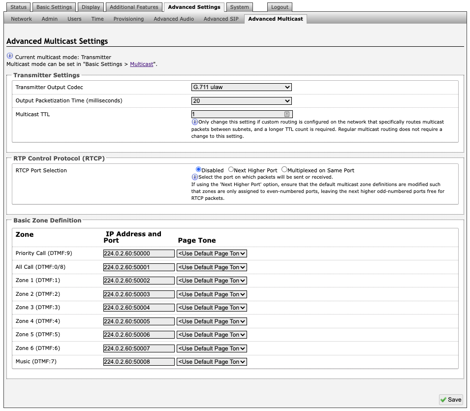
Note
The settings on this tab are only visible when in Sender or Receiver multicast mode.
The default pre-populated multicast addresses above will work in most cases and should only be altered for rare cases.
Transmitter Settings
Transmitter Output Codec
This is the audio encoding format used by the Transmitter device when sending output to the Receivers.
Output Packetization Time (milliseconds)
The size of the audio packets sent by the Transmitter to the Receivers. The default of 20 ms is recommended unless a different value is specifically required for compatibility with other devices.
Multicast TTL
The multicast time to live (TTL) setting should only be changed if custom routing is configured on the network that specifically routes multicast packets between subnets and a longer TTL count is required. This ensures packets are not bounced back and forth in a network identity. When the TTL is reached, the router drops the packet.
Receiver Settings
RTCP Port Selection
Select the port on which RTCP packets will be sent or received. If using the 'Next Higher Port' option, ensure that the default multicast zone definitions are modified such that zones are only assigned to even-numbered ports, leaving the next higher odd-numbered ports free for RTCP packets.
Polycom Receiver Tones
Available if Multicast Receiver and Polycom Group Page or Polycom Push-to-Talk are selected in the Basic Settings → Multicast tab. A tone may be set for any of the 25 Polycom Groups. If using an Algo device as a Multicast Sender, it is recommended to set the Receiver tones to None to avoid conflicts, as the Algo devices already multicast a tone by default.
Basic Zone Definitions
Zones
The Expanded Receiver zones can be enabled/disabled in Basic Settings → Multicast. Default IP addresses and ports may be revised for any given zone in the table.
Note
Ensure that the Address and Port settings are the same for all Sender and Receiver devices.
Page Tone and Page Volume
Sender Mode: By default, the same tone can be set for all Receiver zones in the Basic Settings → Features tab. Unique paging tones may be revised for any given zone in the table above.
Receiver Mode: When an Algo device is the multicast Sender, a page tone will play on the Receiver device, so it is recommended to set the Receiver tone to None. If a page is received from a non-Algo device that doesn’t send a tone, a tone can be inserted on the Receivers (above) each time they detect page audio starting, allowing them to play a tone.
By default, the same page volume can be set for all Receiver zones in the Basic Settings → Features tab. Unique page volumes may be revised on a per-zone basis in the table above. For instance, emergency pages can be louder on certain Receiver speakers.
System
Maintenance
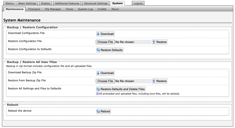
Backup / Restore Configuration
Download Configuration File
Save the device settings to a text file for backup or to set up a provisioning configuration file.
Restore Configuration File
Restore settings from a backup file.
Restore Configuration to Defaults
Resets all 8410/8420 settings to factory default values.
Backup / Restore All User Files
Download Backup Zip File
Saves the device settings (configuration) and all the files in File Manager: certificates, licenses, and tones to a backup zip file.
Restore from Backup Zip File
Restores the device settings (configuration) and all the files in File Manager: certificates, licenses, and tones from a backup zip file.
Restore All Settings and Files to Defaults
Resets the device settings (configuration) and all the files in File Manager: certificates, licenses, and tones to factory default values.
Reboot
Reboot the Device
Reboots the device.
Firmware
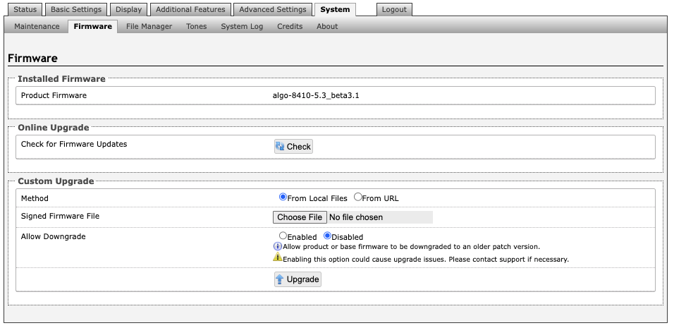
Installed Firmware
Product Firmware
Shows the current firmware on the device.
Online Upgrade
Check for Firmware Updates
Check for the latest firmware. If firmware is current, Latest Firmware will show as Firmware up to date. If firmware needs to be upgraded, the new firmware availability will be listed.
Custom Upgrade
Method
For firmware upgrades. Specify whether the firmware files will be downloaded from the local computer or a remote URL.
Signed Firmware File
To upgrade Firmware:
From the top menu, go to System → Firmware.
In the Upgrade section, press Choose File and select the 8410/8420 firmware file to upload. Note that both FW firmware and MD5 checksum files must be loaded.
Press Upgrade.
After the upgrade is complete, confirm that the firmware version has changed (refer to top right of Control Panel).
Allow Downgrade
Allow product or base firmware to be downgraded to an older patch version. Enabling this option could cause upgrade issues.
File Manager
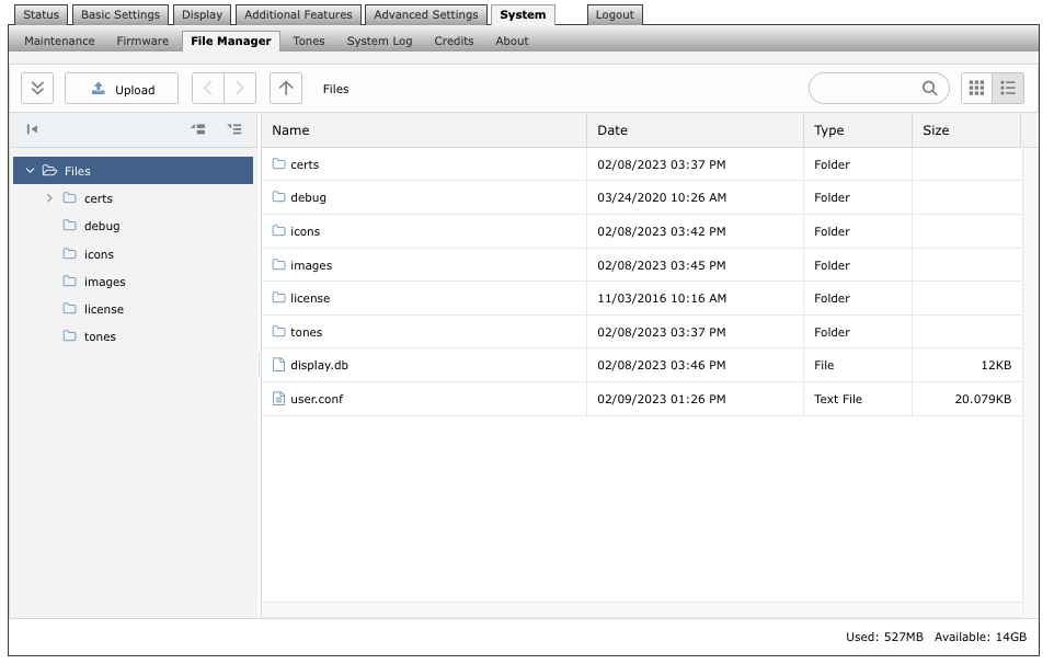
Uploading Custom Audio Files
Custom audio files may be uploaded into memory (1 GB) to play for notification applications. Place your audio files into the tones directory.
An existing file may also be modified. Download the original file and right clicking the tone and selecting Download, making the desired changes, and then uploading the new version with a different name. Audio files must be in the following format:
WAV format
8 kHz or 16 kHz sampling rate
16-bit PCM, or u-law
Mono
Smaller than 200 MB
File names must be limited to 32 characters, with no spaces.
For further instructions reference the Custom Tone Conversion and Upload Guide.
Tones
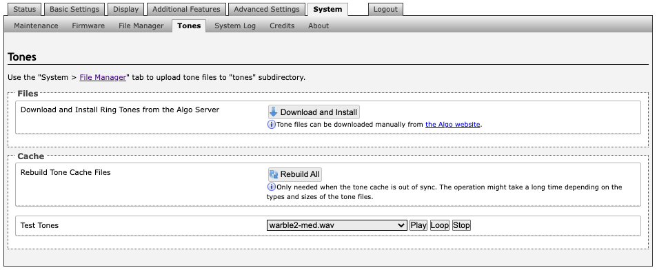
Tone Files Included in Memory
The 8410/8420 includes several pre-loaded audio files that can be selected to play for various events. The web interface allows selection of the file and the ability to play it immediately over the speaker for testing (available in Basic Settings → Features). Files may also be deleted or renamed.
System Log
System log files are automatically created and assist with troubleshooting in the event the 8410/8420 does not behave as expected.
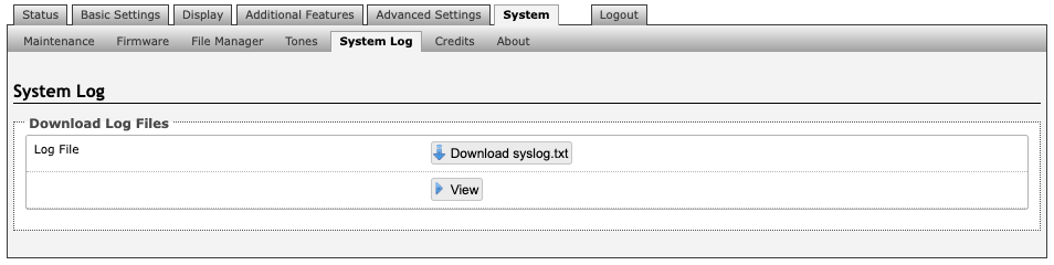
Logout
Log out of the 8410/8420 web interface.
FCC Compliance Statement
This equipment has been tested and found to comply with the limits for a Class A digital device, pursuant to Part 15 of the FCC Rules. These limits are designed to provide reasonable protection against harmful interference when the equipment is operated in a commercial environment. This equipment generates, uses, and can radiate radio frequency energy, and if it is not installed and used in accordance with the instruction manual, it may cause harmful interference to radio communications. Operation of this equipment in a residential area is likely to cause harmful interference, in which case the user will be required to correct the interference at their own expense.